Development of CVD Silica Membranes Having High Hydrogen Permeance and Steam Durability and a Membrane Reactor for a Water Gas Shift Reaction

Abstract
1. Introduction
2. Materials and Methods
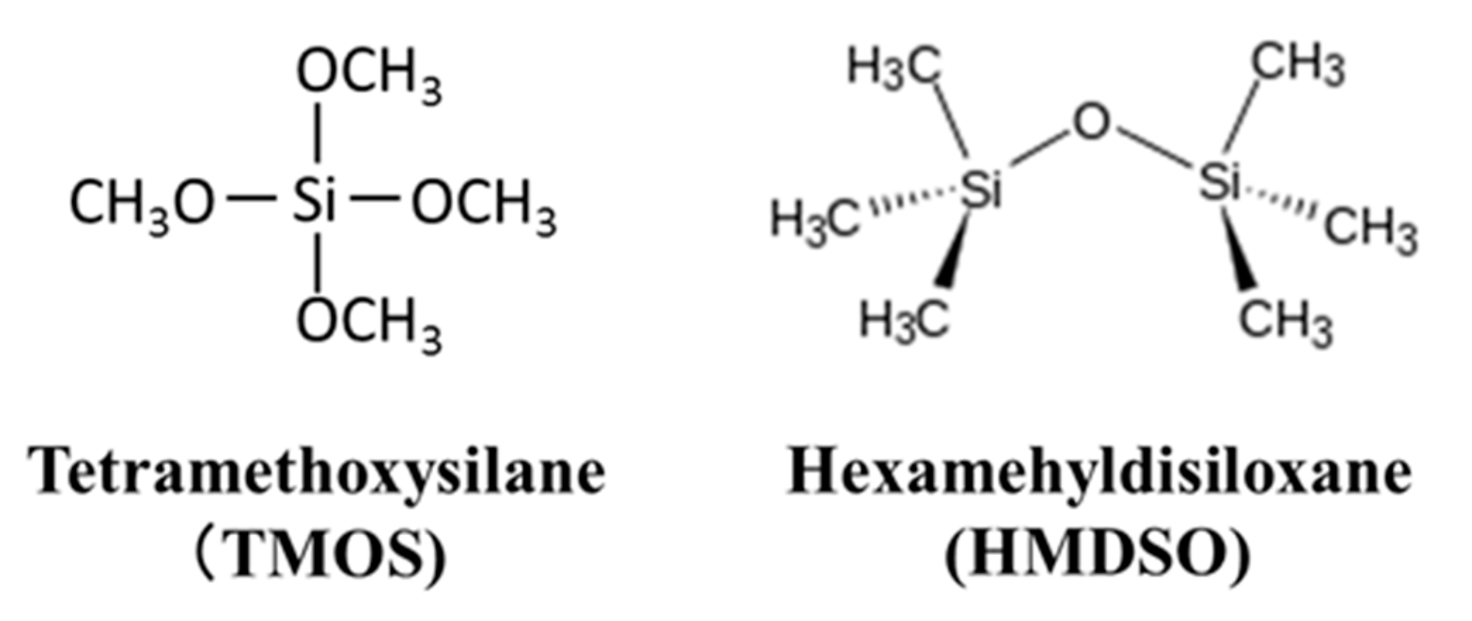
2.1. Preparation and Permeation Measurements of Silica Membranes Derived from TMOS or HMDSO
2.2. Steam Durability Evaluation of Silica Membranes Derived from HMDSO
2.3. Water Gas Shift Reaction with Membrane Reactors Installed Developed Silica Membranes
3. Results and Discussion
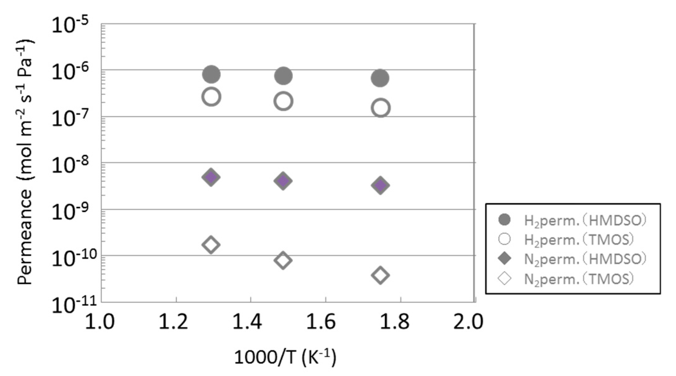
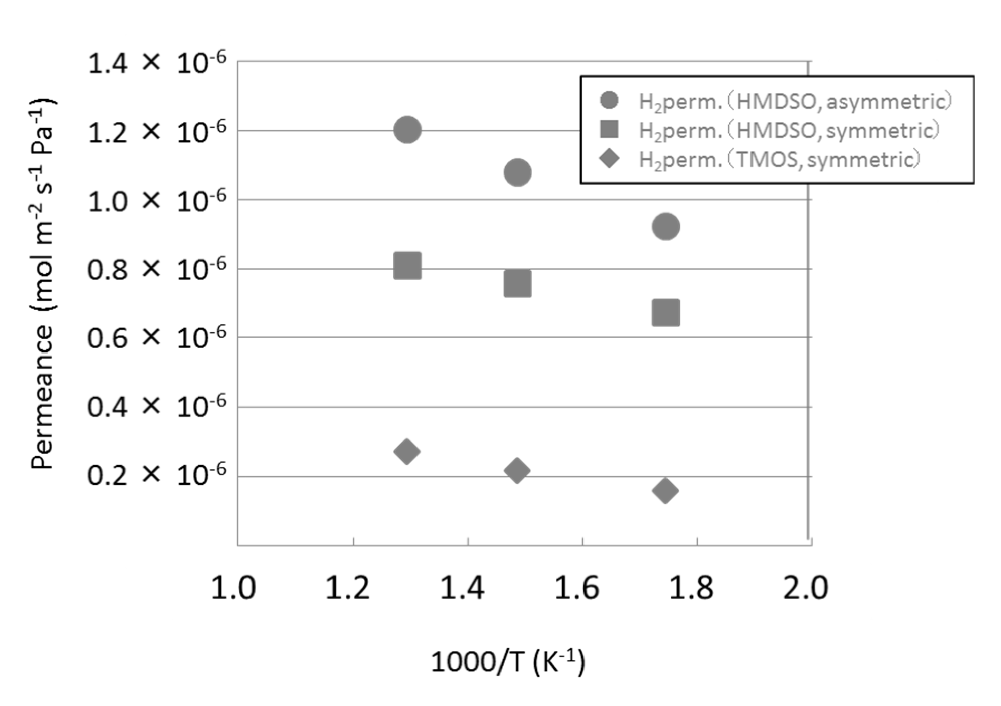
3.1. Permeance of Silica Membranes Derived from TMOS or HMDSO
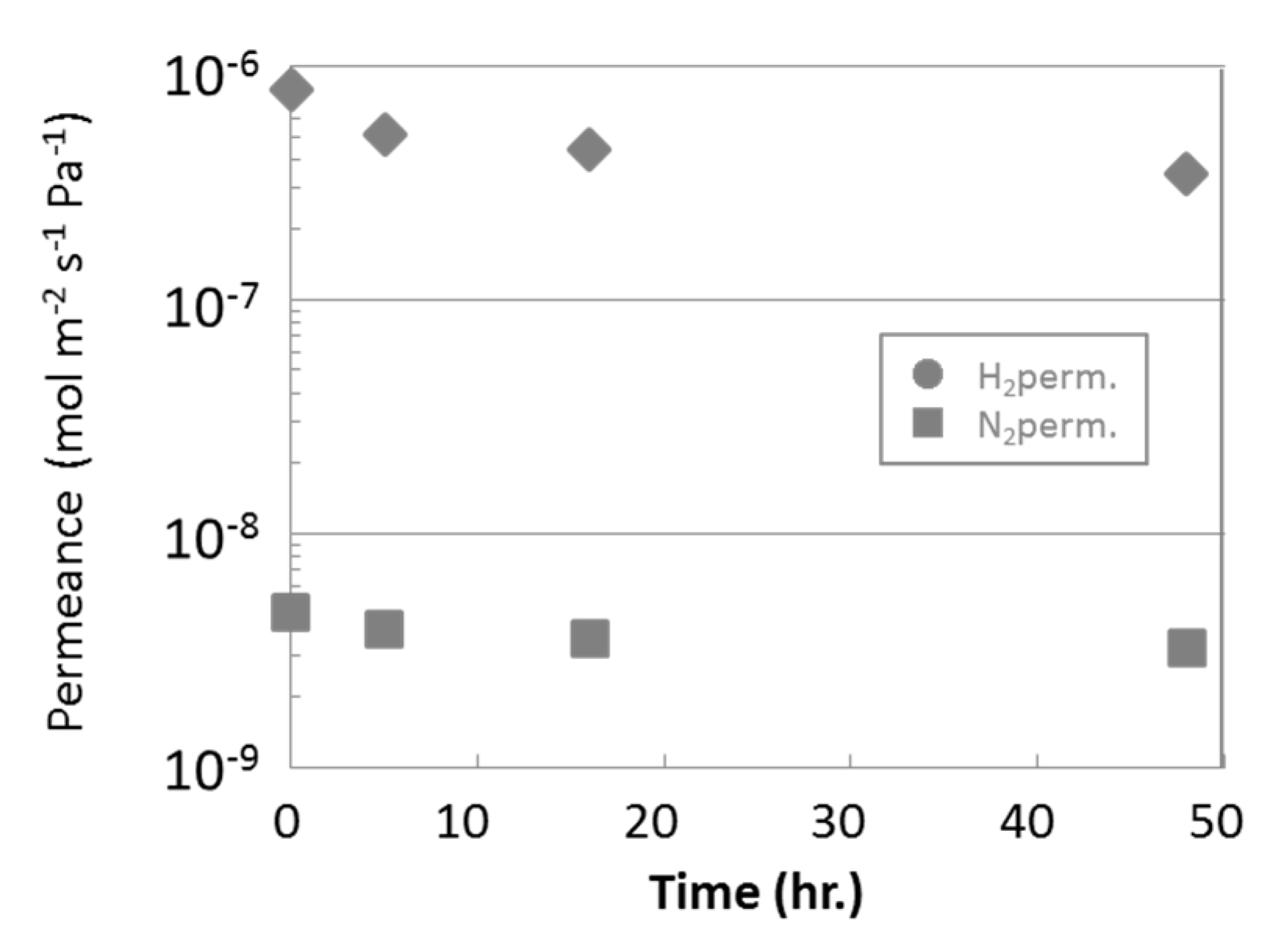
3.2. Steam Durability of Silica Membranes Derived from HMDSO
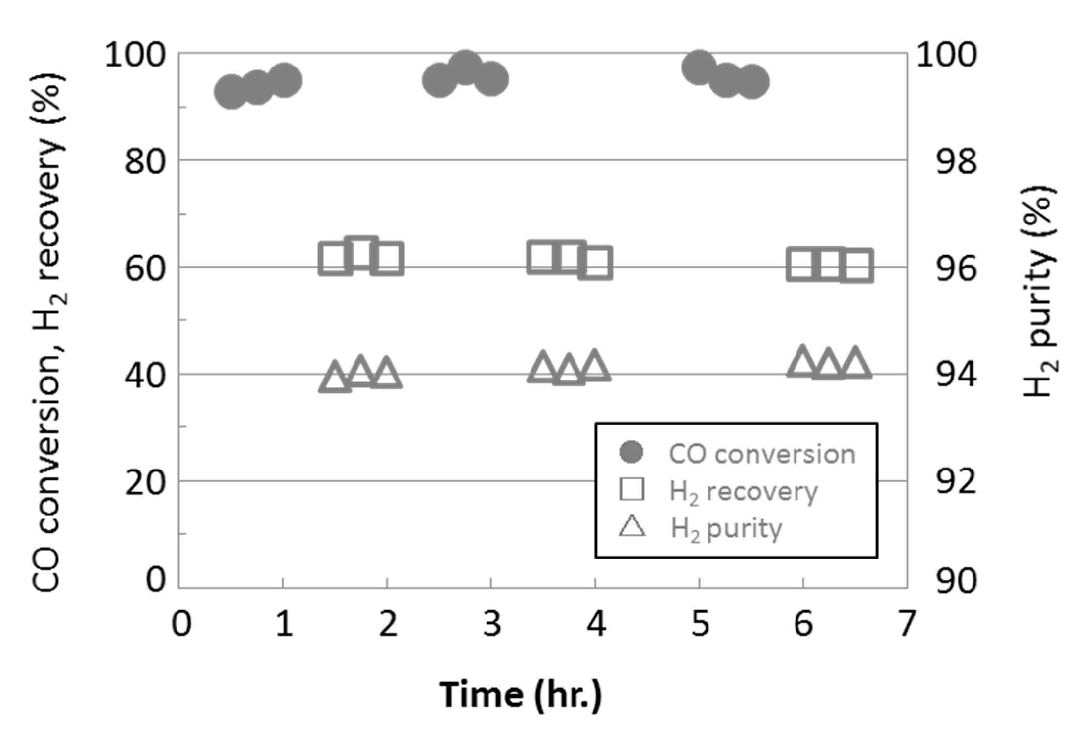
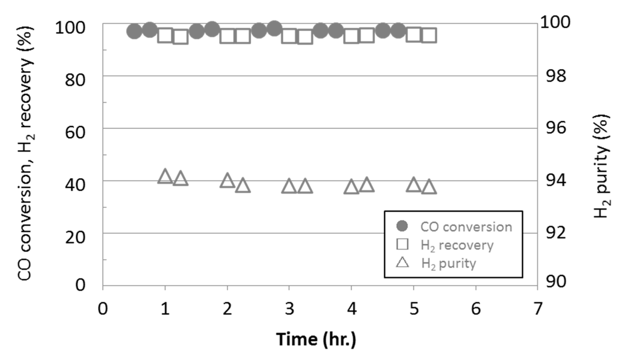
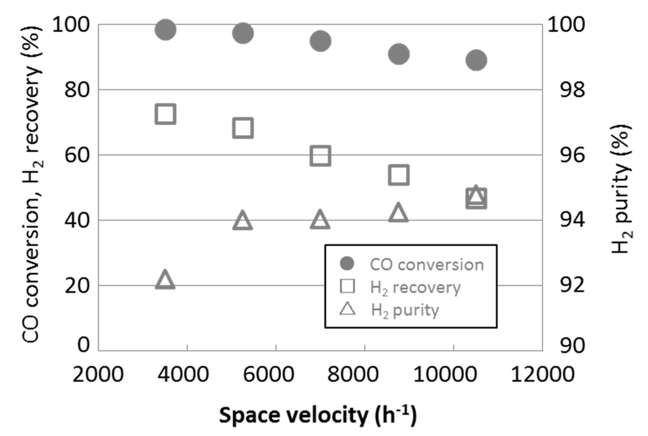
3.3. Water Gas Shift Reaction with Membrane Reactors
4. Conclusions
Author Contributions
Funding
Conflicts of Interest
References
- Sharma, R.; Kumar, A.; Upadhyay, R.K. Performance comparison of methanol steam reforming integrated to Pd-Ag membrane: Membrane reformer vs. membrane separator. Sep. Purif. Technol. 2017, 183, 194–203. [Google Scholar] [CrossRef]
- Ma, L.C.; Castro-Dominguez, B.; Kzantzis, N.K.; Ma, Y.H. A cost assessment study for a large-scale water gas shift catalytic membrane reactor module in the presence of uncertainty. Sep. Purif. Technol. 2016, 166, 205–212. [Google Scholar] [CrossRef]
- Amanipour, M.; Towfighi, J.; Babakhani, E.G.; Heidari, M. H2 permeation properties of a catalytic membrane reactor in methane steam reforming. Int. J. Hydrog. Energy 2016, 10, 1430–1434. [Google Scholar]
- Akamatsu, K.; Tago, T.; Seshimo, M.; Nakao, S.I. Long-term stable H2 production from methylcyclohexane using a membrane reactor with dimethoxydiphenylsilane-derived silica membrane prepared via chemical vapor deposition. Ind. Eng. Chem. Res. 2015, 54, 3996–4000. [Google Scholar] [CrossRef]
- Lima, F.V.; Daoutidis, P.; Tsapatsis, M. Modeling, optimization, and cost analysis of an IGCC plant with a membrane reactor for carbon capture. AIChE J. 2016, 62, 1568–1580. [Google Scholar] [CrossRef]
- Dong, X.; Wang, H.; Rui, Z.; Lin, Y.S. Tubular dual-layer MFI zeolite membrane reactor for hydrogen production via the WGS reaction: Experimental and modeling studies. Chem. Eng. J. 2015, 268, 219–229. [Google Scholar] [CrossRef]
- Allemand, M.; Martin, M.H.; Reyter, D.; Roue, L.; Guay, D.; Botton, G. Synthesis of Cu-Pd alloy thin films by co-electrodeposition. Electrochem. Acta 2011, 56, 7397–7403. [Google Scholar] [CrossRef]
- Seshimo, M.; Ozawa, M.; Sone, M.; Sakurai, M.; Kameyama, H. Fabrication of a novel Pd/γ-alumina graded membrane by electroless plating on nanoporous γ-alumina. J. Membr. Sci. 2008, 324, 181–187. [Google Scholar] [CrossRef]
- Diniz da Costa, J.C.; Lu, G.Q.; Rudolph, V.; Lin, Y.S. Novel molecular sieve silica (MMS) membranes: Characterization and permeation of single-step and two-step sol-gel membranes. J. Membr. Sci. 2002, 198, 9–21. [Google Scholar] [CrossRef]
- Kanezashi, M.; Shioda, T.; Gunji, T.; Tsuru, T. Gas permeation properties of silica membranes with uniform pore size derived from polyhedral oligomeric silsesquioxane. AIChE J. 2012, 58, 1733–1743. [Google Scholar] [CrossRef]
- Seshimo, M.; Akamatsu, K.; Furuta, S.; Nakao, S.-I. Comparative study of the influence of toluene and methylcyclohexane on the performance of dimethoxydiphenylsilane-derived silica membranes prepared by chemical vapor deposition. Sep. Purif. Technol. 2015, 140, 1–5. [Google Scholar] [CrossRef]
- Cao, G.; Lu, Y.; Delattre, L.; Brinker, C.J.; Lopez, G.P. Amorphous silica molecular sieving membranes by sol-gel processing. Adv. Mater. 1996, 8, 588–591. [Google Scholar] [CrossRef]
- De Vos, R.M.; Maier, W.F.; Verweij, H. Hydrophobic silica membranes for gas separation. J. Membr. Sci. 1999, 158, 277–288. [Google Scholar] [CrossRef]
- Iarikov, D.; Hacarlioglu, P.; Oyama, S.T. Amorphous silica membranes for H2 separation prepared by chemical vapor deposition on hollow fiber supports. J. Membr. Sci. 2011, 14, 61–77. [Google Scholar]
- Gavalas, G.R.; Megiris, C.E.; Nam, S.W. Deposition of H2-permselective SiO2 films. Chem. Eng. J. 1989, 44, 1829–1835. [Google Scholar] [CrossRef]
- Ohta, Y.; Akamatsu, K.; Sugawara, T.; Nakao, A.; Miyoshi, A.; Nakao, S.-I. Development of pore size-controlled silica membranes for gas separation by chemical vapor deposition. J. Membr. Sci. 2008, 315, 93–99. [Google Scholar] [CrossRef]
- Nomura, M.; Aida, H.; Gopalakrishnan, S.; Sugawara, T.; Nakao, S.-I.; Yamazaki, S.; Inada, T.; Iwamoto, Y. Steam stability of a silica membrane prepared by counter-diffusion chemical vapor deposition. Desalination 2006, 193, 1–7. [Google Scholar] [CrossRef]
- Miyajima, K.; Eda, T.; Naire, B.N.; Honda, S.; Iwamoto, Y. Hydrothermal stability of hydrogen permselective amorphous silica membrane synthesized by counter-diffusion chemical vapor deposition method. J. Ceram. Soc. Jpn. 2013, 121, 992–998. [Google Scholar] [CrossRef][Green Version]
- Akamatsu, K.; Murakami, T.; Sugawara, T.; Kikuchi, R.; Nakao, S.-I. Stable equilibrium shift of methane steam reforming in membrane reactors with hydrogen-selective silica membranes. AIChE J. 2011, 57, 1882–1888. [Google Scholar] [CrossRef]
- Yoshino, Y.; Suzuki, T.; Nair, B.N.; Taguchi, H.; Itoh, N. Development of tubular substrates, silica based membranes and membrane modules for hydrogen separation at high temperature. J. Membr. Sci. 2005, 267, 8–17. [Google Scholar] [CrossRef]
- Akamatsu, K.; Nakane, M.; Sugawara, T.; Nakao, S.-I. Performance under thermal and hydrothermal condition of amorphous silica membrane prepared by chemical vapor deposition. AIChE J. 2009, 55, 2197–2200. [Google Scholar] [CrossRef]
- Smart, S.; Vente, J.F.; Diniz da Costa, J.C. High temperature H2/CO2 separation using cobalt oxide silica membranes. Int. J. Hydrog. Energy 2012, 37, 12700–12707. [Google Scholar] [CrossRef]
- Karakiliç, P.; Huiskes, C.; Luiten-Olieman, M.W.J.; Nijmeijer, A.; Winnubst, L. Sol-gel processed magnesium-doped silica membranes with improved H2/CO2 separation. J. Membr. Sci. 2019, 543, 195–201. [Google Scholar] [CrossRef]
- Song, H.; Wei, Y.; Qi, H. Tailoring pore structures to improve the permselectivity of organosilica membranes by tuning calcination parameters. J. Mater. Chem. A. 2017, 5, 24657–24666. [Google Scholar] [CrossRef]


| Samples | Selectivity (H2/N2) |
|---|---|
| HMDSO-derived silica membrane (asymmetric substrate) | 265 |
| HMDSO-derived silica membrane (symmetric substrate) | 209 |
| TMOS-derived silica membrane (symmetric substrate) | 4230 |
| Samples | Selectivity (H2/N2) |
|---|---|
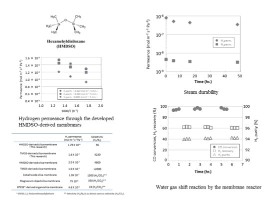
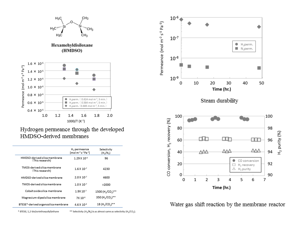
| HMDSO-derived silica membrane (0.624 mol m−3, 3 min) | 96 |
| HMDSO-derived silica membrane (0.584 mol m−3, 5 min) | 107 |
| HMDSO-derived silica membrane (0.885 mol m−3, 5 min) | 265 |
| Samples | H2 Permeance (mol m−2 s−1 Pa−1) | Selectivity (H2/N2) |
|---|---|---|
| HMDSO-derived silica membrane (This research) | 1.29 × 10⁻⁶ | 96 |
| TMOS-derived silica membrane (This research) | 1.6 × 10⁻⁷ | 4230 |
| HMDSO-derived silica membrane [19] | 2.0 × 10⁻⁷ | 4600 |
| TMOS-derived silica membrane [21] | 1.0 × 10⁻⁷ | >2000 |
| Cobalt oxide silica membrane [22] | 1.9 × 10⁻⁷ | 1500 (H2/CO2) ** |
| Magnesium-diped silica membrane [23] | 7 × 10⁻⁸ | 350 (H2/CO2) ** |
| BTESE*-derived organosilica membrane [24] | 4.6 × 10⁻⁸ | 18 (H2/CO2) ** |
© 2019 by the authors. Licensee MDPI, Basel, Switzerland. This article is an open access article distributed under the terms and conditions of the Creative Commons Attribution (CC BY) license (http://creativecommons.org/licenses/by/4.0/).
Share and Cite
Nishida, R.; Tago, T.; Saitoh, T.; Seshimo, M.; Nakao, S.-i. Development of CVD Silica Membranes Having High Hydrogen Permeance and Steam Durability and a Membrane Reactor for a Water Gas Shift Reaction. Membranes 2019, 9, 140. https://doi.org/10.3390/membranes9110140
Nishida R, Tago T, Saitoh T, Seshimo M, Nakao S-i. Development of CVD Silica Membranes Having High Hydrogen Permeance and Steam Durability and a Membrane Reactor for a Water Gas Shift Reaction. Membranes. 2019; 9(11):140. https://doi.org/10.3390/membranes9110140
Chicago/Turabian StyleNishida, Ryoichi, Toshiki Tago, Takashi Saitoh, Masahiro Seshimo, and Shin-ichi Nakao. 2019. "Development of CVD Silica Membranes Having High Hydrogen Permeance and Steam Durability and a Membrane Reactor for a Water Gas Shift Reaction" Membranes 9, no. 11: 140. https://doi.org/10.3390/membranes9110140
APA StyleNishida, R., Tago, T., Saitoh, T., Seshimo, M., & Nakao, S.-i. (2019). Development of CVD Silica Membranes Having High Hydrogen Permeance and Steam Durability and a Membrane Reactor for a Water Gas Shift Reaction. Membranes, 9(11), 140. https://doi.org/10.3390/membranes9110140