Article

Corrosion Protection of Al/Au/ZnO Anode for Hybrid Cell Application

Bioelectronics Laboratory, Department of Computer Science and Electrical Engineering, University of Maryland Baltimore County, Baltimore, MD 21250, USA
*
Author to whom correspondence should be addressed.
Membranes 2015, 5(4), 739-751; https://doi.org/10.3390/membranes5040739
Submission received: 18 September 2015 / Accepted: 11 November 2015 / Published: 16 November 2015
(This article belongs to the Special Issue Membranes for Electrochemical Energy Applications 2015)

Abstract

:
Effective protection of power sources from corrosion is critical in the development of abiotic fuel cells, biofuel cells, hybrid cells and biobateries for implantable bioelectronics. Corrosion of these bioelectronic devices result in device inability to generate bioelectricity. In this paper Al/Au/ZnO was considered as a possible anodic substrate for the development of a hybrid cell. The protective abilities of corrosive resistant aluminum hydroxide and zinc phosphite composite films formed on the surface of Al/Au/ZnO anode in various electrolyte environments were examined by electrochemical methods. The presence of phosphate buffer and physiological saline (NaCl) buffer allows for the formation of aluminum hyrdroxide and zinc phosphite composite films on the surface of the Al/Au/ZnO anode that prevent further corrosion of the anode. The highly protective films formed on the Al/Au/ZnO anode during energy harvesting in a physiological saline environment resulted in 98.5% corrosion protective efficiency, thereby demonstrating that the formation of aluminum hydroxide and zinc phosphite composite films are effective in the prevention of anode corrosion during energy harvesting. A cell assembly consisting of the Al/Au/ZnO anode and platinum cathode resulted in an open circuit voltage of 1.03 V. A maximum power density of 955.3 μW/ cm2 in physiological saline buffer at a cell voltage and current density of 345 mV and 2.89 mA/ cm2, respectively.

1. Introductions

Approximately 8% to 10% of Americans and 5% to 6% of the industrialized world’s population have implantable bioelectronic devices [1]. The bioelectronic device implant and biocompatible material market in the United States are 12 and 11 billion dollar industries, respectively. These markets are increasing about 9% every year [2]. Implantable bioelectronics are used for treating diseases, birth defects and the aging population for the overall improvement in the quality of life of the inflicted individuals. This further leads to the reduction of health care costs of the overall population. These implantable bioelectronics range from organ and neuro-stimulators [3] and regeneration devices [4], pacemakers [5,6,7], drug delivery devices [8,9], sensors [10,11,12], and activation circuits that monitor orthopedic implants [13]. These implantable devices could someday be powered by implantable power sources. Most implantable bioelectronics require an internal source of power, which can be accomplished with the help of implantable power sources such as, biobatteries, hybrid cells, biofuel cells and abiotic fuel cells that use abiotic anode or enzymatic anode to catalyze natural occurring fuel inside the body. The Al/Au/ZnO nanostructured anodes have been employed to selectively catalyze glucose in the presence of oxygen in a glucose/ O2 fuel cell [14], as well as to generate bioelectricity by activating the Al underneath the ZnO as anodic material in a hybrid cell supplied with phosphate rich electrolyte [15] in the realization of implantable power sources.
In addition, implantable bioelectronic power sources use biomaterials to enhance the biocompatibility, longevity and corrosion protection of the implantable devices from the harsh environments of the body [16,17,18] without adverse side effects. The body is an extremely corrosive environment because of cations such as Na+, K+, Ca+, Mg+, anions such as chloride, bicarbonate, phosphate, and large amounts of dissolved oxygen found throughout the body [19,20,21]. These molecules upset the chemical balance on the surface of implanted materials that lead to the consumption of these materials via anodic or cathodic reactions through galvanic corrosion. This corrosion occurs mostly with metallic substrates used to provide structural rigidity and electrical conduction path in bioelectronic devices. The main cause of corrosion comes from oxidation and reduction reactions between metallic materials and biological fluids. In particular, Cl ions and dissolved oxygen are the major factors in corrosion within the body because of their ability to deteriorate metal substrates. Moreover, implant corrosion can cause serious side effects because of the release of metal anions into the surrounding environments and blood stream. These ions harm the body by either direct toxic effects or local hypersensitivity reactions. Elements such as nickel, cobalt, and chromium as well as their compounds are known allergens [22,23]. Aluminum [24], copper and zinc [25] ions have been associated with Alzheimer’s disease as well as other neurological disorders such as epilepsy. These effects of corrosion from implantable devices has heightened the need for corrosion prevention, especially when harvesting energy from within the body.
Traditionally, corrosion protection is achieved through phosphating using acidic phosphate baths that use nitrates and nitrites. This process has been found to be harmful to the environment [26], whereas anodic acceleration has been employed to produce biocompatible zinc phosphate and zinc phosphate’s hydrated tertiary form, hopeite [27], in physiological conditions using basic neutral pH and buffer solutions. This allows phosphating to occur utilizing biocompatible materials [28,29,30,31,32,33] which not only prevent corrosion but could also generate electricity for biomedical applications. This process can be defined as a biomimetic coating treatment because the process mimics an in vivo process for the application of phosphate coatings on an anodic substrate. These biomimetic coatings have also been demonstrated for magnesium substrates by several research groups [34,35], but biomimetic zinc phosphite research has yet to be performed. Here, we explore the application of corrosion prevention for the protection of bioelectronic power sources. Without corrosion protection, bioelectronics devices cease to produce reliable power and can leach harmful metal ions into the body.
In this paper, we take advantage of an economical biomimetic phosphating approach with the ability to form zinc phosphite film in physiological conditions, while generating bioelectricity. The Al/Au/ZnO anode is used for anodic electrochemical treatment in a phosphate rich bath to create corrosion resistive films as well as to produce power for bioelectronic applications. Our approach utilizes a low-cost and “green” alternative method that demonstrates effective corrosion resistance of the anodic substrate. We demonstrate that Al/Au/ZnO anode can be protected in a saline rich solution by the formation of zinc phosphites under physiological conditions rather than using other acidic, high energy and expensive techniques. This technique could be implemented in the body as described by Heller et al. [30] as corrosion protection for a bioelectronics power supply for implanted electrical devices.

2. Material and Methods

Aluminum foil (99.9999%, 250 mm thick) substrates were cleaned with acetone, isopropanol and deionized water in preparation and fabrication of the Al/Au/ZnO anode using a sol–gel processes [34,35,36]. Magnetron sputtering was used to sputter 40 nm of gold to coat the surface of aluminum substrates. The aluminum (Al) surface activation was achieve via ZnO nanocrystal before zinc phosphating in an Al/phosphate hybrid cell. ZnO precursors were prepared by using 0.4 M zinc chloride (99.99%) and isopropanol. The solution was mixed at 75 °C and equimolar triethenamine was added to stabilize the precursor solution to yield a 0.1 M homogenous ZnO nanosol, which was aged at 85 °C. The ZnO seed layers were deposited on the Al/Au substrate using a dip coating method upon aging of the solution. The solvent was allowed to naturally evaporate followed by annealing at 150 °C for 1 hour. The dip coat method was repeated multiple times to create a uniform seed layer and finally dried at 30 °C in a convection oven for 12 hours [14,15,36].
All current-voltage and power curves were obtained by acquiring the current and voltage through and across a variable load. Device durability tests of the assembled cell were performed with the Al/Au/ZnO anode and a Pt cathode at a load of 3 kΩ, since the maximum power for the hybrid cells were obtained at a load of 3 kΩ, while monitoring the corrosion protection of the anode in various electrolyte environments. Every two days, the spent electrolyte (saline: 2.7 mM KCl and 137 mM NaCl or physiological saline: 20 mM phosphate, 2.7 mM KCl and 137 mM NaCl, pH 7.4) was exchange of for a fresh electrolyte.
The formation of the corrosion protection layer (aluminum hydroxide and phosphite) on the Al/Au/ZnO anode was achieved by discharging the anode in physiological saline using a two-electrode cell configuration (platinum served as the cathode) across 3 kΩ resistor for 10–15 min. Polarization curves were obtained for both bare Al, Al/Au, untreated Al/Au/ZnO, saline treated Al/Au/ZnO and aluminum hydroxide and phosphite coated Al/Au/ZnO anodes in 20 mM phosphate buffer solution at room temperature using a three-electrode cell configuration. Ag/AgCl and platinum electrode were used as the reference and counter electrodes, respectively. The protective abilities of corrosive resistant films formed on the surface of Al/Au/ZnO anode in different electrolyte environments were examined using electrochemical impedance spectroscopy. An a.c. potential of 10 mVp-p was applied over the frequency range of 100 kHz to 10 mHz.

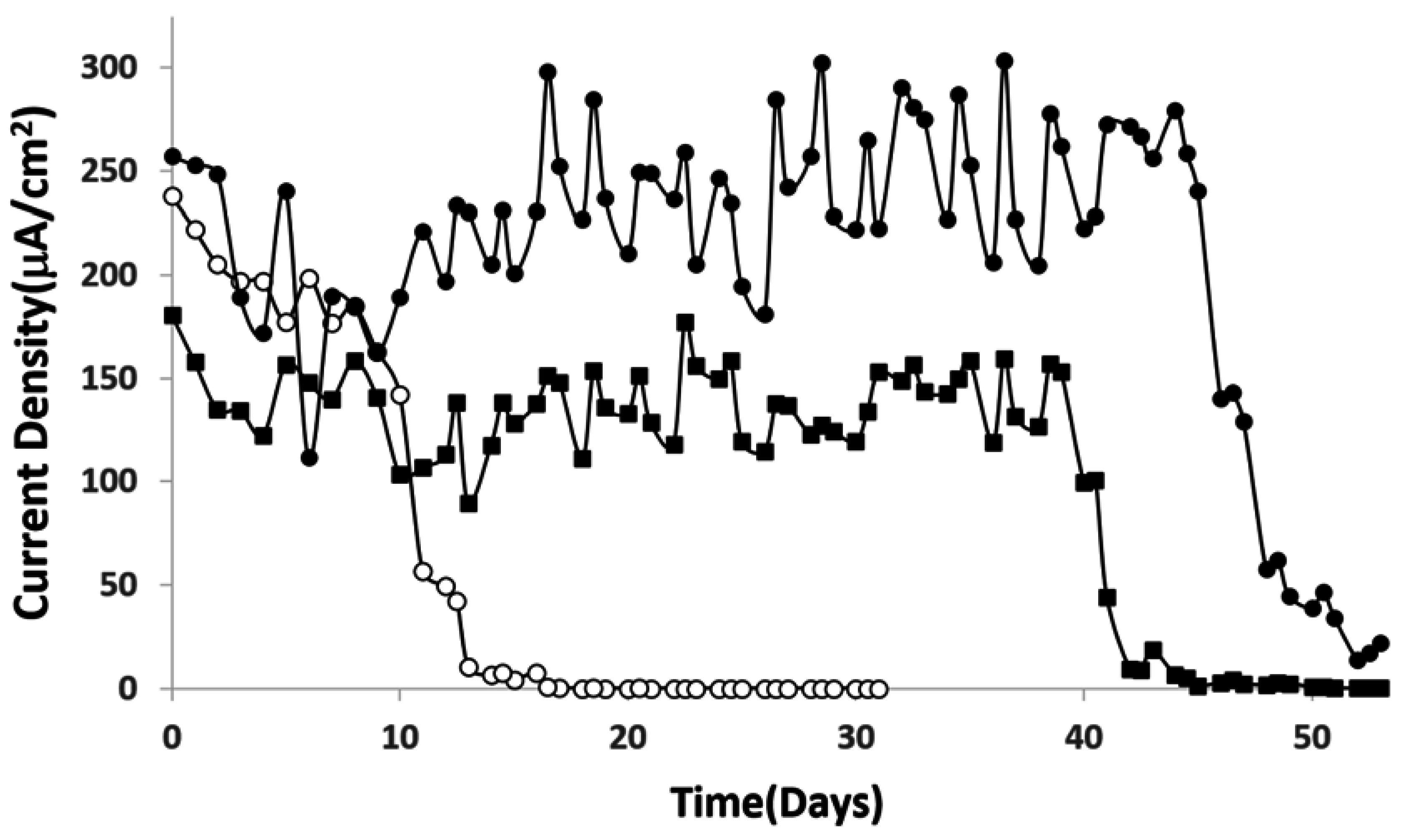
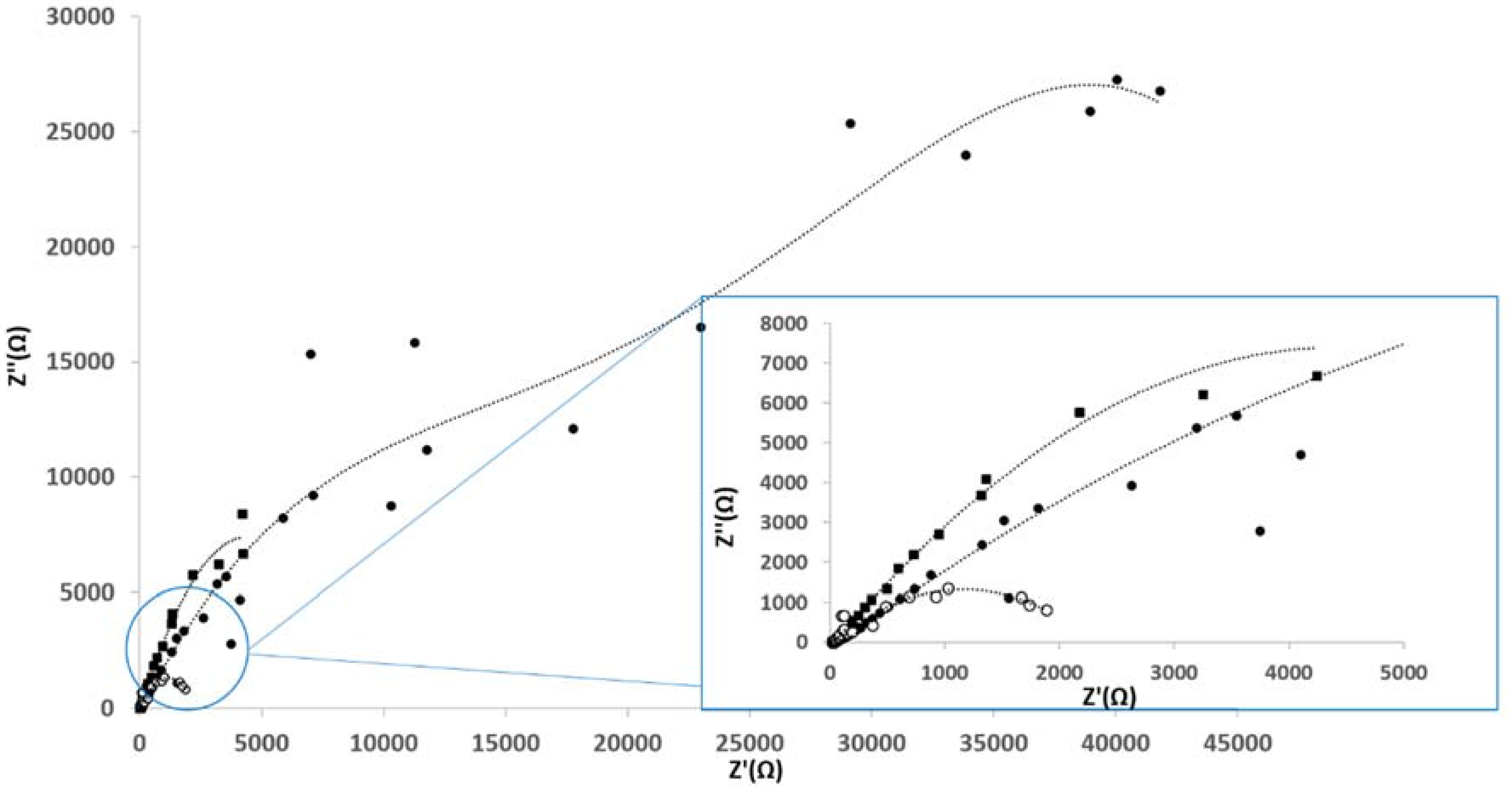
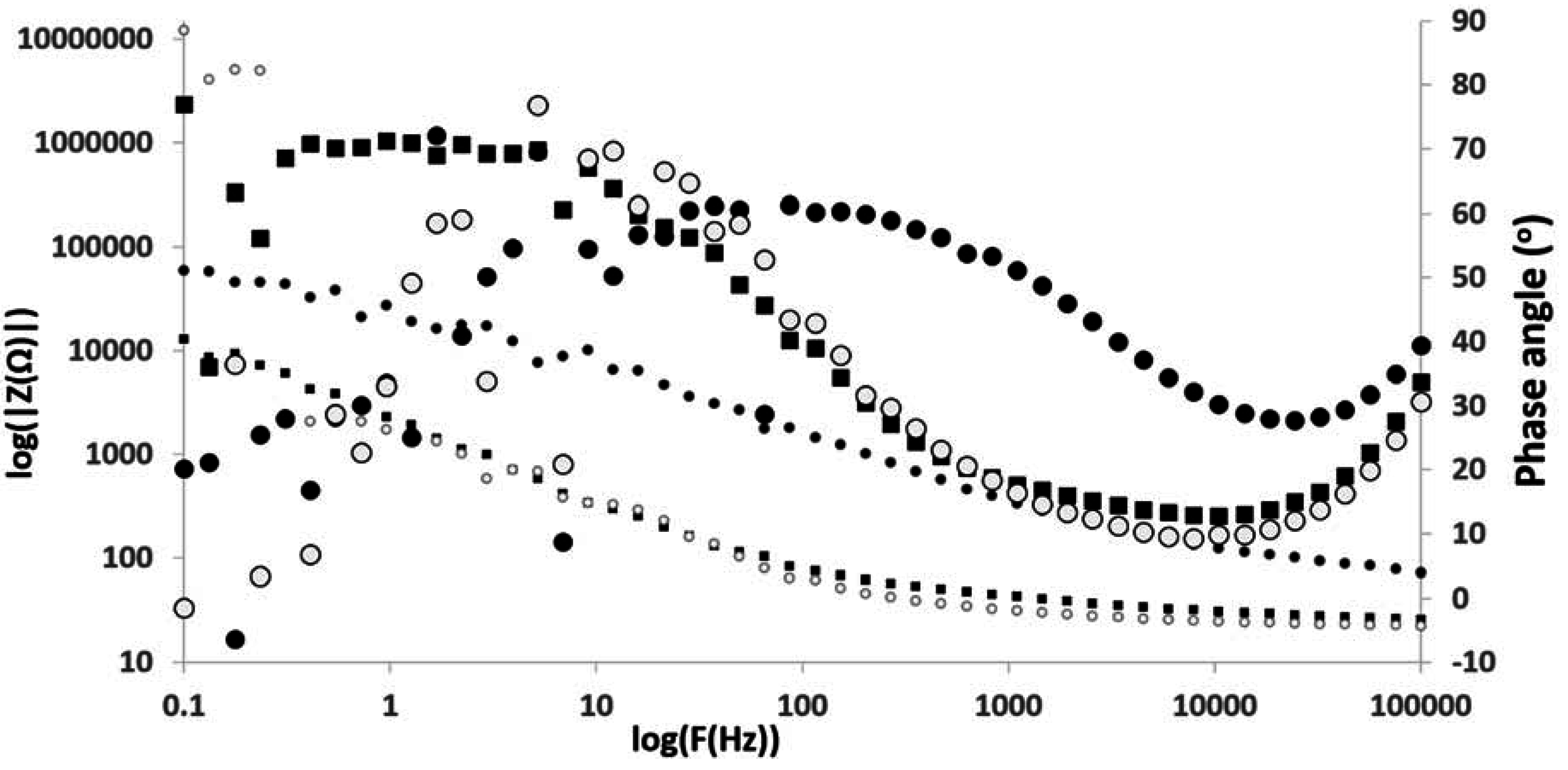
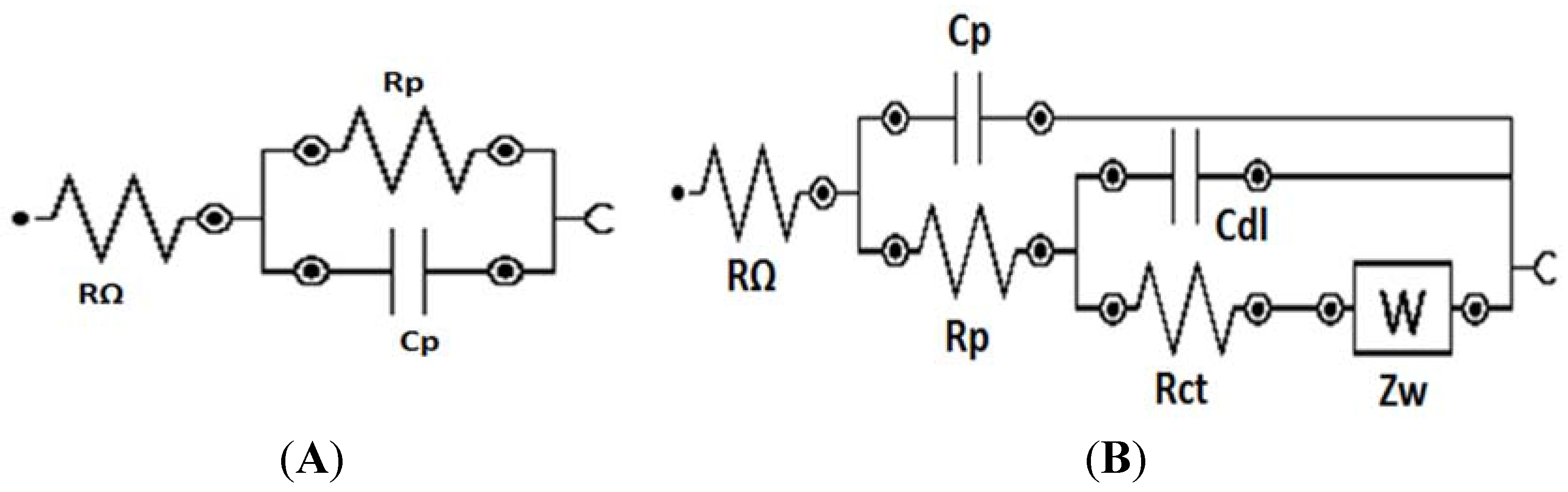
3. Results and Discussion

The as-prepared Al/Au/ZnO anodes (1 cm × 0.5 cm) and platinum cathodes (ϕ = 500 μm) were assembled to realize a hybrid cell operating in physiological saline buffer (pH 7.4) saturated with O2. In the hybrid cell, the nanostructured ZnO plugged in on the anodic electrode surface (Figure 1A) results in the Al/Al3+ oxidation via pitting mechanism originating from the defect site to overcome the thin oxide film on the Al substrate in physiological saline. The oxidation of the byproduct of the anodic reaction, hydrogen, results in the release of electrons that recombines with the H2PO4 ions on the surface of the platinum cathode to reduce it to HPO32− ions. These ions then react with Zn2+ release from ZnO nanocrystals and the adsorption and precipitation of HPO32− results in the formation of Al(OH)3 and ZnHPO3 composite on the anode (Figure 1B). The current-voltage and power characteristics were acquired immediately upon assembling the hybrid cell and are shown in Figure 2. This cell achieved a 6-fold increase in performance compared to the previously reported Al/Au/ZnO anode in abiotic fuel cell application [15]. The maximum power density in physiological saline buffer was 955.3 μW/ cm2 at a cell voltage of 345 mV with approximately the same open circuit voltage value. This enhancement in performance can be attributed to the increased ZnO nanoseed layer deposited on the Al/Au substrate. The highest maximum power density reported to date is achieved using Al/Au/ZnO anode described here when compared to enzymatic and abiotic fuel cells and biobatteries that use biological fluids as an electrolyte. Briefly, enzymatic fuel cells have the potential to exhibit long life spans but lack in high electrical characteristics when compared with lithium ion cells [37,38]. Although, enzymatic biofuel cells have been reported to last for 3 months, continuous operation was only observed over a period of 9 days [39]. This shortcoming is due to the loss of enzyme activity, thereby resulting in shorter device lifetime. On the other hand, biobatteries and abiotic fuel cells have been able to produce the most comparable electrical properties that may closely match lithium ion cells but have only shown to survive for a few weeks at most [28,31]. The cell described here was able to produce almost 10 times more power than recently reported abiotic fuel cells [40,41], around 5 times more power than enzymatic biofuel cells [31,42,43,44,45], 2 to 6 times more power than biobattery that uses a zinc phosphate anode [28,31] and has a 1.25 times more current density that of the traditional lithium ion cell [46,47].
Figure 1. Scanning electron micrograph of Al/Au/ZnO anode (A) before and (B) after discharging in physiological saline (pH 7.4, 20 mM phosphate, 2.7 mM KCl and 137 mM NaCl) to form nonporous aluminum hydroxide and zinc phosphite lamellae layer on the anode.
Membranes 05 00739 g001
Figure 2. Current-voltage characterization and power impact curves of the hybrid cell in O2-saturated phosphate buffered saline.
Membranes 05 00739 g002
The durability of the cells employing Al/Au/ZnO anodes and platinum cathodes were operated continuously under a 3 kΩ load in all three separate electrolyte environments are depicted in Figure 3. Polarization curves were obtained once a day for 55 days, with the electrolyte environment being exchanged with fresh electrolyte every two days. Overall, the results show good durability and stability of voltage and current density. Upon operating the cell in saline solution, significant deterioration of the anode was observed. The Al/Au/ZnO anode in this environment was immediately discolored, followed by the appearance of pits in week 4. In week 6, the anode was completely corroded, which led to the complete decomposition of the Al/Au/ZnO anode. In this saline environment, the Cl ions deteriorate the oxide layer on the anode, resulting in a lack of corrosion protection of the Al/Au/ZnO anode. However, the current density of the cell operating in phosphate buffer dropped significantly after 10 days of continuous operation, whereas the cell operating in physiological saline rich solution maintained its stability over 40 days of operation. The addition of a halide salt such as NaCl may contribute to the formation of nonporous aluminum hydroxide and zinc phosphite lamellae layer [30] on the surface of the anode in physiological saline that provides corrosion protection of the A/Au/ZnO anode because the film acts as non-oxidizing anode inhibitors, thereby preventing galvanic corrosion of the anode and ionic current flow. The formation of the composite lamellae layer further inhibits power generation during long term durability testing.
Figure 3. Stability curve of the hybrid cell continuously operating in O2-saturated (○) phosphate buffer, (▪) saline, and (●) physiological saline buffer environments.
Membranes 05 00739 g003
Electrochemical impedance spectroscopy (EIS) was performed to evaluate the inhibitive properties of the corrosion protection composite films. Nyquist and Bode phase angle plots of Al/Au/ZnO anodes (1 cm × 0.5 cm) treated in saline and physiological saline electrolyte environments for a period of 55 days are shown in Figure 4 and Figure 5. The typical electrical equivalent circuit obtained for coated metal surfaces exposed to corrosive environments [48] agree with the electrical equivalent circuit for the Al/Au/ZnO anodes presented in Figure 6. Figure 6A represent the equivalent circuit model for Al/Au/ZnO metal/ electrolyte interface, where RΩ is the solution resistance, Rp is the polarization resistance, and Cp is the coating capacitance. The equivalent circuit shown in Figure 6B, with the Warburg element (Zw), represents the Al/Au/ZnO anode coated with aluminum hydroxide and zinc phosphite composite film upon discharging in physiological saline, where Rct is the charge transfer resistance and Cdl is the double layer capacitance. This anode exhibited very small high frequency capacitive loop and is nearly shielded by a diffusion tail in the low frequency domain, thereby showing Warburg behavior. The Nyquist and Bode plots for the coated anode are different from those of the saline treated anode. The high frequency capacitive loop in the Nyquist plot is evident in the saline treated Al/Au/ZnO anode. In the Bode plot, the maximum phase angle is found to be 67.1° and is shifted towards the low frequency region. These results reveal the absence of a corrosion protective film on the saline treated anodic surface. One time constant was observed for the saline treated anode, which suggest that it could only influence the charge transfer process. The |Z| vs. f curves also shows a decrease in impedance values for the saline treated anode, which suggest the formation of conductive paths in the ZnO film is due to water uptake and the penetration of corrosive Cl ions that deteriorates the ZnO layer and the anodic substrate.
Figure 4. Nyquist plots of (○) untreated Al/Au/ZnO, () saline treated Al/Au/ZnO, and (●) Al(OH)3 and ZnHPO3 coated Al/Au/ZnO anodes.
Membranes 05 00739 g004
Figure 5. Impedance vs. Frequency plots and Bode phase plots for (○) untreated Al/Au/ZnO, () saline treated Al/Au/ZnO, and () Al(OH)3 and ZnHPO3 coated Al/Au/ZnO anodes.
Membranes 05 00739 g005
Figure 6. Equivalent electrical circuit utilized to model the impedance behavior of (A) saline treated Al/Au/ZnO and (B) Al(OH)3 and ZnHPO3 coated Al/Au/ZnO anodes.
Membranes 05 00739 g006
The aluminum hydroxide and zinc phosphite coated anode exhibited a Warburg behavior, which indicate the inhomogeneity of corrosion protection film on the anode surface. This film aids in the prevention of the diffusion of oxygen or Cl ions to the Al substrate and thus inhibits the corrosion of the anode, while enabling the transport of Zn2+ in the ZnO conductivity layer. A larger partial semicircle is observed from high frequency to low frequency indicating that the charge transfer resistance is dominant in the corrosion process due to the presence of corrosion protection film on the anode. This is also supported by the Bode plots, in which the phase angle maximum is slightly decreased (61°) and shifted towards higher frequency region compared to the saline treated anode. At anode surfaces coated with aluminum hydroxide and zinc phosphite upon discharging physiological saline environment, the phase angle maximum shows two time constants. The maximum in the low frequency domain relates to the porous ZnO films on the Al surface and the second maximum in the higher frequency domain relates to the charge transfer resistance by the corrosion protection film. The |Z| vs. f curves shows an increase in impedance values, which infers that the protective surface film is a combination of zinc oxide film, aluminum hydroxide and zinc phosphite [15]. The formation of aluminum hydroxide and zinc phosphite on the Al/Au/ZnO anode results in a larger charge transfer resistance, Rct, value 20.8 kΩ cm2, whereas smaller values of 4.48 and 4.17 kΩ cm2 was observed for the saline treated and the phosphate buffer treated anodes, respectively. The double layer capacitance, Cdl, value of 1.50 µF cm−2 for the aluminum hydroxide and zinc phosphite coated anode is lower than that of 48.3 and 32.5 µF cm−2 observed for the saline treated and phosphate buffer treated anodes, respectively. An admittance of the constant phase element of the double layer was only observed for the aluminum hydroxide and zinc phosphite coated anode, which can be attributed to the formation of a densely packed dielectric film or an increase of the double layer thickness. The high Rct and lower Cdl values of the composite film on Al/Au/ZnO anode discharged in physiological saline reveal the dense protective film formation on the surface of Al/Au/ZnO anode.
In addition, the Al/Au/ZnO anodes were examined after the 55 days discharge in saline, phosphate buffer and physiological saline environments. The polarization behavior of the Al/Au/ZnO anodes are depicted in Figure 7. The bare Al/Au anode shows higher anodic activity than that of the bare Al anode, suggesting the Al/Au is more inert than the bare Al. The corrosion potential (Ecorr) and corrosion current density (icorr) can be determined using the Tafel extrapolation method [49] and are approximated with the position of the anodic current in the polarization curves. The activation of Al via nano-ZnO seeds deposited on the surface of Al/Au anode allow for zinc ions to react with phosphite groups to form aluminum hydroxide and zinc phosphite composite in phosphate buffer and physiological saline buffer [15]. The Al/Au/ZnO anode coated with this protective film shifts the potential of the anode to become more anodic and thus decreases corrosion current and enhances the electrical properties. This shift toward more anodic values allows for an increased deposition of the corrosion protection film [50], which further suggests an increased corrosion resistance. The protective efficiency P ( % ) of the Al/Au/ZnO anode coated with aluminum hydroxide and zinc phosphite composite film was determined by [51]:
P ( % ) = 100   ( 1 K f K f 0 )
where K f and K f 0 are the faradaic conductances in the presence and absence of the composite film, respectively. Here the protective efficiency of 98.5% was calculated for the Al/Au/ZnO anode coated with aluminum hydroxide and zinc phosphite composite film. The polarization behavior of the Al/Au/ZnO anode coated with this protective film demonstrates the effective corrosion protection of the anode.
Figure 7. Polarization curves for (∆) bare Al, (□) bare Al/Au, (○) untreated Al/Au/ZnO, and (●) Al(OH)3 and ZnHPO3 coated Al/Au/ZnO anodes.
Membranes 05 00739 g007
The aluminum hydroxide and zinc phosphite composite films are impermeable to O2 and thus prevent corrosion [28,30] even in the presence of NaCl for over one month and allow for increased cell performance. Therefore, the cell operating in physiological saline buffer resulted in the most durable cell, lasting up to 50 days. The observed life span of the Al/Au/ZnO anode in physiological saline is much longer that previously reported abiotic fuel cells [28,29,30]. The enhanced durability of the cell operating in physiological saline buffer suggests that localized sites of aluminum hydroxide and zinc phosphite composite film enable the development of micro regions on the surface of the anode to allow Zn2+ ions to react with phosphites to form corrosion protection film while reducing the galvanic current [52]. Thereby, resulting in an improved corrosion resistance when operating in physiological saline buffer.

4. Conclusion

The corrosion protection of the as-fabricated Al/Au/ZnO anode was characterized in saline, phosphate rich buffer and physiological saline buffer. The Al/Au/ZnO anode discharged in phosphate rich buffer and physiological saline buffer showed protection against corrosion via the formation of aluminum hydroxide and zinc phosphite films. The resulting corrosion resistant anode led to improved electrical properties (current density) and extended life span of the hybrid fuel cell when compared to abiotic fuel cells based on similar anodes. The use of the sol–gel dip coating process yielded a much larger surface area of zinc oxide, which was employed to activate the aluminum anode. The biomimetic approach employed in this work is more economical and environmentally safe compared to other techniques that require harmful nitrates, nitrites, acidic baths and high energy equipment. Here, we demonstrate a novel approach to providing corrosion resistant films on Al/Au/ZnO anodes while harvesting energy. The cell exhibited an enhanced performance and extended lifetime over other abiotic fuel cells. The excellent performance of the cell can be attributed to the combined effect of the cathode and the Al/Au/ZnO anode that operated in physiological saline buffer to achieve an open circuit voltage of 1.03 V. The Al/Au/ZnO has significant potential for developing long lasting hybrid cells.

Acknowledgment

This work was supported by the National Science Foundation (Award ECCS-#1349603).

Author Contributions

Gymama Slaughter conceived and designed this study. Brian Stevens carried out the experiments and was supervised by Gymama Slaughter. All authors discussed the results, interpreted the data, wrote the manuscript and approved the manuscript.

Conflicts of Interest

The authors declare no conflict of interest.

References

  1. Jiang, G.; Zhou, D. Technology advances and challenges in hermetic packaging for implantable medical devices. In Implantable Neural Prostheses 2; Springer: New York, NY, USA, 2010; pp. 27–61. [Google Scholar]
  2. Yun, Y.; Dong, Z.; Lee, N.; Liu, Y.; Xue, D.; Guo, X.; Kuhlmann, J.; Doepke, A.; Halsall, B.; Heineman, W.; et al. Revolutionizing biodegradable metals. Mater. Today 2009, 12, 22–32. [Google Scholar] [CrossRef]
  3. Samani, M.; Mahnam, A.; Hosseini, N. An Arbitrary Waveform Wearable Neuro-stimulator System for Neurophysiology Research on Freely Behaving Animals. J. Med. Signals Sens. 2014, 4, 94–102. [Google Scholar] [PubMed]
  4. Bennet, D.; Kim, S. Implantable microdevice for peripheral nerve regeneration: materials and fabrications. J. Mater. Sci. 2011, 46, 4723–4740. [Google Scholar] [CrossRef]
  5. Okamoto, E.; Inoue, T.; Watanabe, K.; Hashimoto, T.; Iwazawa, E.; Abe, Y.; Chinzei, T.; Isoyama, T.; Kobayashi, S.; Saito, I.; et al. Development of an Implantable High-Energy and Compact Battery System for Artificial Heart. Artif. Organs 2003, 27, 184–188. [Google Scholar] [CrossRef] [PubMed]
  6. DeRosa, J.F.; Beard, R.; Carim, H.; Dubin, S. Polarization and Corrosion Studies of Porous and Solid Anodes for Implantable Power-Generating Electrodes. IEEE Trans. Biomed. Eng. 1973, 5, 345–349. [Google Scholar] [CrossRef] [PubMed]
  7. Wilson, D.; Herweg, B. New Technology for Implantable Cardioverter Defibrillators. Card. Electrophysiol. Clin. 2014, 6, 261–267. [Google Scholar] [CrossRef]
  8. Chanlen, T.; Hongeng, S.; Nasongkla, N. Tri-component copolymer rods as an implantable reservoir drug delivery system for constant and controllable drug release rate. J. Polym. Res. 2012, 19, 1–12. [Google Scholar] [CrossRef]
  9. Gensler, H.; Sheybani, R.; Li, P.; Mann, R.; Meng, E. An implantable MEMS micropump system for drug delivery in small animals. Biomed. Microdevices 2012, 14, 483–496. [Google Scholar] [CrossRef] [PubMed]
  10. Juanola-Feliu, E.; Miribel-Català, P.; Páez Avilés, C.; Colomer-Farrarons, J.; González-Piñero, M.; Samitier, J. Design of a customized multipurpose nano-enabled implantable system for in vivo theranostics. Sensors 2014, 14, 19275–19306. [Google Scholar] [CrossRef] [PubMed] [Green Version]
  11. Novak, M.T.; Yuan, F.; Reichert, W.M. Macrophage embedded fibrin gels: An in vitro platform for assessing inflammation effects on implantable glucose sensors. Biomaterials 2014, 35, 9563–9572. [Google Scholar] [CrossRef] [PubMed]
  12. Vaddiraju, S.; Legassey, A.; Qiang, L.; Wang, Y.; Burgess, D.; Papadimitrakopoulos, F. Enhancing the Sensitivity of Needle-Implantable Electrochemical Glucose Sensors via Surface Rebuilding. J. Diabetes Sci. Technol. 2013, 7, 441–451. [Google Scholar] [CrossRef] [PubMed]
  13. Morais, R.; Frias, C.; Silva, N.; Azevedo, J.; Serôdio, C.; Silva, P.; Ferreira, J.; Simões, J.; Reis, M. An activation circuit for battery-powered biomedical implantable systems. Sens. Actuators A Phys. 2009, 156, 229–236. [Google Scholar] [CrossRef]
  14. Slaughter, G.; Sunday, J. A membraneless single compartment abiotic glucose fuel cell. J. Power Sources 2014, 261, 332–336. [Google Scholar] [CrossRef]
  15. Slaughter, G.; Sunday, J.; Stevens, B. Energy conversion from aluminium and phosphate rich solution via ZnO activation of aluminium. Mater. Chem. Phys. 2015, 163, 245–252. [Google Scholar] [CrossRef]
  16. Williams, D. The Williams Dictionary of Biomaterials; Liverpool University Press: Liverpool, UK, 1999. [Google Scholar]
  17. Williams, D. On the nature of biomaterials. Biomaterials 2009, 30, 5897–5909. [Google Scholar] [CrossRef] [PubMed]
  18. Slaughter, G. Improving the Biocompatibility of Implantable Bioelectronics Devices. In Implantable Bioelectronics; Katz, E., Ed.; Wiley-VCH Verlag GmbH & Co. KGaA: Weinheim, Germany, 2014; pp. 265–283. [Google Scholar]
  19. Anderson, J. Biological responses to materials. Annu. Rev. Mater. Res. 2001, 31, 81–110. [Google Scholar] [CrossRef]
  20. Nail-plates, F. Corrosion of orthopaedic implants. J. Bone Jt. Surg. 1959, 41B, 810–820. [Google Scholar]
  21. Williams, D. Tissue-biomaterial interactions. J. Mater. Sci. 1987, 22, 3421–3445. [Google Scholar] [CrossRef]
  22. Aksakal, B.; Yildirim, Ö.S.; Gul, H. Metallurgical failure analysis of various implant materials used in orthopedic applications. J. Fail. Anal. Prev. 2004, 4, 17–23. [Google Scholar] [CrossRef]
  23. Reclaru, L.; Lerf, R.; Eschler, P.-Y.; Meyer, J.-M. Corrosion behavior of a welded stainless-steel orthopedic implant. Biomaterials 2001, 22, 269–279. [Google Scholar] [CrossRef]
  24. Drago, D.; Bettella, M.; Bolognin, S.; Cendron, L.; Scancar, J.; Milacic, R.; Ricchelli, F. Potential pathogenic role of β-amyloid 1–42–aluminum complex in Alzheimer’s disease. Int. J. Biochem. Cell Biol. 2008, 40, 731–746. [Google Scholar] [CrossRef] [PubMed]
  25. Yao, F.; Zhang, R.; Tian, H.; Li, X. Studies on the interactions of Copper and Zinc ions with β-Amyloid peptides by a surface plasmon resonance biosensor. Int. J. Mol. Sci. 2012, 13, 11832–11843. [Google Scholar] [CrossRef] [PubMed]
  26. United States Environmental Protection Agency (USEPA). Nitrates and Nitrites: TEACH Chemical Summary; USEPA: Washington, DC, USA, 2007.
  27. Kouisni, L.; Azzi, M.; Zertoubi, M.; Dalard, F.; Maximovitch, S. Phosphate coatings on magnesium alloy AM60 part 1: Study of the formation and the growth of zinc phosphate films. Surf. Coat. Technol. 2004, 185, 58–67. [Google Scholar] [CrossRef]
  28. Shin, W.; Lee, J.; Kim, Y.; Steinfink, H.; Heller, A. Ionic Conduction in Zn3(PO4)2·4H2O Enables Efficient Discharge of the Zinc Anode in Serum. J. Am. Chem. Soc. 2005, 127, 14590–14591. [Google Scholar] [CrossRef] [PubMed]
  29. Shin, W.; Lee, J.; Lee, J.; Park, Y.; Heller, A. Zinc Anode Operating in Physiological Condition. In Proceedings of the 215th The Electrochemical Society (ECS) Meeting, San Francisco, CA, USA, 24–29 May 2009; Abstract #242. pp. 242–242.
  30. Heller, A. Potentially implantable miniature batteries. Anal. Bioanal. Chem. 2006, 385, 469–473. [Google Scholar] [CrossRef] [PubMed]
  31. Stolarczyk, K.; Kizling, M.; Majdecka, D.; Żelechowska, K.; Biernat, J.; Rogalski, J.; Bilewicz, R. Biobatteries and biofuel cells with biphenylated carbon nanotubes. J. Power Sources 2014, 249, 263–269. [Google Scholar] [CrossRef]
  32. Skunik-Nuckowska, M.; Grzejszczyk, K.; Stolarczyk, K.; Bilewicz, R.; Kulesza, P. Integration of supercapacitors with enzymatic biobatteries toward more effective pulse-powered use in small-scale energy harvesting devices. J. Appl. Electrochem. 2014, 44, 497–507. [Google Scholar] [CrossRef]
  33. Nguyen, T.; Waterman, J.; Staiger, M.; Woodfield, T. Controlling in vitro corrosion rate of pure Mg with rough surface texture via biomimetic coating systems. Corros. Eng. Sci. Technol. 2012, 47, 358–364. [Google Scholar] [CrossRef]
  34. Waterman, J.; Birbilis, N.; Dias, G.J.; Woodfield, T.B.F.; Staiger, M.P. Improving in vitro corrosion resistance of biomimetic calcium phosphate coatings for Mg substrates using calcium hydroxide layer. Corros. Eng. Sci. Technol. 2012, 47, 340–345. [Google Scholar] [CrossRef]
  35. Xia, W.; Lindahl, C.; Engqvist, H.; Lausmaa, J. Biomimetic hydroxyapatite deposition on titanium oxide surfaces for biomedical application. In Advances in Biomimetics; INTECH Open Access Publisher: Rijeka, Croatia, 2011. [Google Scholar]
  36. Raoufi, D.; Raoufi, T. The effect of heat treatment on the physical properties of sol–gel derived ZnO thin films. Appl. Surf. Sci. 2009, 255, 5812–5817. [Google Scholar] [CrossRef]
  37. Barton, S.C. Handbook of Fuel Cells: Advances in Electrocatalysis, Materials, Diagnostics and Durability; John Wiley & Sons: Hoboken, NJ, USA, 2009. [Google Scholar]
  38. Minteer, S.; Liaw, B.; Cooney, M. Enzyme-based biofuel cells. Curr. Opin. Biotechnol. 2007, 18, 228–234. [Google Scholar] [CrossRef] [PubMed]
  39. Zebda, A.; Cosnier, S.; Alcaraz, J.; Holzinger, M.; Le Goff, A.; Gondran, C.; Bouche, F. Single glucose biofuel cells implanted in rats power electronic devices. Sci. Rep. 2013, 3. [Google Scholar] [CrossRef] [PubMed]
  40. Hussein, L.; Urban, G. An Abiotically Catalyzed Glucose Fuel Cell Based on Decorated Buckypaper. In Proceedings of the 14th International Conference on Miniaturized Systems for Chemistry and Life Sciences, Groningen, The Netherlands, 3–7 October 2010.
  41. Oncescu, V.; Erickson, D. A microfabricated low cost enzyme-free glucose fuel cell for powering low-power implantable devices. J. Power Sources 2011, 196, 9169–9175. [Google Scholar] [CrossRef]
  42. Halámková, L.; Halámek, J.; Bocharova, V.; Szczupak, A.; Alfonta, L.; Katz, E. Implanted biofuel cell operating in a living snail. J. Am. Chem. Soc. 2012, 134, 5040–5043. [Google Scholar] [CrossRef] [PubMed]
  43. Szczupak, A.; Halámek, J.; Halámková, L.; Bocharova, V.; Alfonta, L.; Katz, E. Living battery—Biofuel cells operating in vivo in clams. Energy Environ. Sci. 2012, 5, 8891–8895. [Google Scholar] [CrossRef]
  44. MacVittie, K.; Halámek, J.; Halámková, L.; Southcott, M.; Jemison, W.; Lobel, R.; Katz, E. From “cyborg” lobsters to a pacemaker powered by implantable biofuel cells. Energy Environ. Sci. 2013, 6, 81–86. [Google Scholar] [CrossRef]
  45. Cinquin, P.; Gondran, C.; Giroud, F.; Mazabrard, S.; Pellissier, A.; Boucher, F.; Alcaraz, J.-P. A glucose biofuel cell implanted in rats. PLoS One 2010, 5, e10476. [Google Scholar] [CrossRef] [PubMed]
  46. Dahn, J.; Jiang, J.; Mushurchak, L.; Buhrmester, C.; Wang, R. The drugstore Li-ion cell. Electrochem. Soc. Interface 2005, 14, 27–31. [Google Scholar]
  47. Dahn, J.; Jiang, J.; Moshurchak, L.; Fleischauer, M.; Buhrmester, C.; Krause, L. High-rate overcharge protection of LiFePO4-based Li-ion cells using the redox shuttle additive 2, 5-ditertbutyl-1, 4-dimethoxybenzene. J. Electrochem. Soc. 2005, 152, A1283–A1289. [Google Scholar] [CrossRef]
  48. Chen, X-B.; Zhou, X.; Abbott, T.; Easton, M.; Birbilis, N. Double-layered manganese phosphate conversion coating on magnesium alloy AZ91D: Insights into coating formation, growth and corrosion resistance. Surf. Coat. Technol. 2013, 217, 147–155. [Google Scholar]
  49. Jegannathan, S.; Narayanan, T.S.N.; Ravichandran, N.; Rajeswari, S. Performance of zinc phosphate coatings obtained by cathodic electrochemical treatment in accelerated corrosion tests. Electrochim. Acta 2005, 51, 247–256. [Google Scholar] [CrossRef]
  50. Jegannathan, S.; Narayanan, T.S.N.; Ravichandran, N.; Rajeswari, S. Formation of zinc phosphate coating by anodic electrochemical treatment. Surf. Coat. Technol. 2006, 200, 6014–6021. [Google Scholar] [CrossRef]
  51. Tsuji, N.; Nozawa, K.; Aramaki, K. Ultrathin protective films prepared by modification of an N,N-dimethylalkylamine monolayer with chlorosilanes for preventing corrosion of iron. Corros. Sci. 2000, 42, 1523–1538. [Google Scholar] [CrossRef]
  52. Li, G.Y.; Lian, J.S.; Niu, L.Y.; Jiang, Z.H.; Jiang, Q. Growth of zinc phosphate coatings on AZ91D magnesium alloy. Surf. Coat. Technol. 2006, 201, 1814–1820. [Google Scholar] [CrossRef]

