Review

Membrane-Based CO2 Capture Across Industrial Sectors: Process Conditions, Case Studies, and Implementation Insights

by
Jin Woo Park
1,2,
Soyeon Heo
1,
Jeong-Gu Yeo
1,3,
Sunghoon Lee
4,
Jin-Kuk Kim
2 and
Jung Hyun Lee
1,*
1
Energy Storage Research Department, Korea Institute of Energy Research, Daejeon 34129, Republic of Korea
2
Chemical Engineering Department, Hanyang University, Seoul 04763, Republic of Korea
3
Division of Energy Engineering, KIER School, University of Science and Technology, Daejeon 34129, Republic of Korea
4
CCS Research Department, Korea Institute of Energy Research, Daejeon 34129, Republic of Korea
*
Author to whom correspondence should be addressed.
Membranes 2025, 15(7), 200; https://doi.org/10.3390/membranes15070200
Submission received: 2 June 2025 / Revised: 20 June 2025 / Accepted: 27 June 2025 / Published: 2 July 2025
(This article belongs to the Special Issue Novel Membranes for Carbon Capture and Conversion)

Abstract

Membrane-based CO2 capture has emerged as a promising technology for industrial decarbonization, offering advantages in energy efficiency, modularity, and environmental performance. This review presents a comprehensive assessment of membrane processes applied across major emission-intensive sectors, including power generation, cement, steelmaking, and biogas upgrading. Drawing from pilot-scale demonstrations and simulation-based studies, we evaluate how flue gas characteristics, such as CO2 concentration, pressure, temperature, and impurity composition, govern membrane selection, process design, and operational feasibility. Case studies highlight the technical viability of membrane systems under a wide range of industrial conditions, from low-CO2 NGCC flue gas to high-pressure syngas and CO2-rich cement emissions. Despite these advances, this review discusses the key remaining challenges for the commercialization of membrane-based CO2 capture and includes perspectives on process design and techno-economic evaluation. The insights compiled in this review are intended to support the design of application-specific membrane systems and guide future efforts toward scalable and economically viable CO2 capture across industrial sectors.

1. Introduction

Global CO2 emissions, driven by human activities, have significantly accelerated climate change, raising atmospheric concentrations from 316 ppm in 1960 to a projected 426 ppm by 2025 and contributing to a 1.1 °C rise in average global temperature since pre-industrial times [1,2]. The rise in greenhouse gas emissions—primarily from fossil fuel use, deforestation, and agricultural expansion—has intensified climate-related impacts and highlighted the urgent need for technologies that can directly reduce or remove atmospheric CO2 [3,4,5,6,7,8,9,10].
Accordingly, CO2 capture technologies have been developed over the past decades, and efforts to effectively capture, store, and utilize CO2 emitted from various industrial sectors are still ongoing. For instance, the CO2 concentration in flue gas emitted from power plants, manufacturing facilities, and biogas upgrading processes shows a wide range, ranging from approximately 4% to 50% (Table 1) [11,12]. In addition, the presence of secondary components and impurities, together with the need for pretreatment, can significantly affect the efficiency of the capture process [13]. Accordingly, process design optimized for each condition is essential to achieve efficient CO2 capture across a range of technological options.
A range of CO2 capture technologies—including absorption, adsorption, membrane separation, cryogenic separation, and biological approaches—have been developed, each offering distinct advantages and limitations. As summarized in Table 2, while chemical absorption is effective for large-scale emitters, it incurs high solvent regeneration costs [1,14,15,16]. Adsorption requires substantial thermal input [17,18,19,20], cryogenic methods yield high-purity CO2 at high energy costs [21,22,23], and biological capture, though eco-friendly, is limited by slow uptake and large space requirements, underscoring the need for an integrated approach tailored to application-specific demands [24,25].
Membrane-based CO2 separation offers several advantages over conventional capture technologies, such as ease of operation, low energy consumption, and system simplicity [26,27,28,29,30,31]. Unlike absorption or adsorption methods, membranes enable CO2 separation without chemical reactions or solvent regeneration, resulting in a more environmentally benign and operationally straightforward process. Their compact design allows for easy integration into industrial systems, making them particularly suitable for decentralized or small-scale emission sources where conventional large-scale systems may not be feasible [32]. Additionally, membrane performance becomes more favorable when the CO2 concentration in flue gas exceeds 20%, as higher partial pressure enhances the driving force for selective gas permeation, leading to improved separation efficiency [12,33,34]. Therefore, the selection of an appropriate CO2 capture technology should be guided by the composition, temperature, and environmental characteristics of the target flue gas, as each method only demonstrates commercial viability when applied under conditions that maximize its advantages. This review focuses on industrial case studies of membrane-based CO2 capture processes, analyzing their configurations, performance metrics, and applicability across various emission sources. While both membrane gas absorption (e.g., membrane contactors) and membrane gas separation have been investigated for CO2 capture, this review focuses exclusively on the latter. Membrane gas absorption utilizes a liquid absorbent at the gas–liquid interface within porous membranes and is governed by reactive mass transfer mechanisms. In contrast, membrane gas separation relies on selective gas phase permeation through dense or composite membranes. Due to fundamental differences in transport mechanisms, operational configuration, and scalability, membrane absorption is excluded from the scope of this review, except for brief contextual comparisons where relevant.

2. Membrane Process for CO2 Capture

Membrane-based gas separation proceeds through three key steps: gas sorption at the feed side, diffusion across the membrane driven by a concentration gradient, and desorption at the permeate side. The process enables selective CO2 separation based on differences in gas permeabilities, which are governed by the physicochemical characteristics of the membrane material [35,36,37]. CO2 transport is driven by the pressure differential between the feed and permeate sides, and the flux can be modulated using compressors or vacuum pumps depending on the process’s configuration [38,39,40,41]. The overall performance of membrane systems is primarily influenced by the operating conditions, such as the feed pressure, permeate pressure, flow rate, and temperature [41,42,43,44,45,46,47,48,49,50].
Notably, trade-offs often arise between permeance and selectivity, as well as CO2 purity and recovery, necessitating precise optimization of membrane process parameters. Among the most influential factors is the choice of membrane material, which determines critical performance metrics, such as permeability, selectivity, and long-term stability. Membranes are fabricated in various structural formats, including thin-film composite (TFC) and facilitated transport membranes (FTMs), but they are broadly classified by their base materials into three categories, polymers, ceramics, and mixed-matrix membranes (MMMs), each tailored to specific operating environments.
Polymeric membranes, such as those made from polysulfone, polyimide, and Pebax, are commonly used due to their favorable CO2 selectivity and ease of processing. However, they are susceptible to plasticization and thermal aging degradation. Numerous studies have shown that strategies like polymer blending copolymerization can enhance mechanical and thermal stability [51]. Ceramic membranes, composed of materials like silica or alumina, offer exceptional resistance to heat and chemical corrosion, making them suitable for harsh conditions, such as those found in pre-combustion CO2 capture. Despite these advantages, their brittleness, water sensitivity, and high production costs have limited large-scale deployment [52,53]. MMMs that embed inorganic fillers, such as metal–organic framework (MOFs) or zeolites, into polymer matrices aim to combine the mechanical flexibility of polymers with the superior selectivity of inorganic materials. Recent advancements have demonstrated that well-designed MMMs can surpass the traditional Robeson upper bound, particularly in post-combustion capture scenarios [54]. This alignment is critical not only because of process compatibility but also due to intrinsic material limitations that impose performance boundaries [55].
While operational parameters are crucial for process optimization, intrinsic material limitations often impose more fundamental constraints on membrane performance. In particular, the inherent trade-off between permeability and selectivity remains a major challenge in the development of high-performance membranes. A well-recognized bottleneck in membrane-based CO2 separation is the permeability–selectivity trade-off, often visualized by the Robeson upper bound. This empirical relationship highlights that enhancing gas permeability typically leads to a loss in selectivity, making it difficult to achieve both high CO2 flux and high purity simultaneously. Such limitations are especially critical in industrial applications where low CO2 partial pressures, high flow rates, and economic constraints demand both performance and scalability. For instance, low driving forces necessitate membranes with high selectivity, but this often comes at the expense of permeance, requiring larger membrane areas and higher compression energy. Recent materials research, however, has shown promising approaches to mitigating this trade-off. N. Habib et al. demonstrated that incorporating ionic-modified metal–organic frameworks with 177 fillers into Pebax membranes significantly enhanced CO2/N2 selectivity, exceeding the Robeson upper bound under simulated flue gas conditions [56]. Similarly, a study reported ultrathin Polymethyl methacrylate composite membranes with improved H2/CO2 performance [57], while A. E. Amooghin et al. utilized MXene-based mixed-matrix membranes to achieve simultaneous improvements in both permeability and selectivity [58]. These findings emphasize that overcoming the permeability–selectivity trade-off is not only a matter of material innovation but also essential for ensuring the industrial feasibility of membrane-based CO2 capture systems.
Numerous studies have emphasized that the operating conditions of membrane systems significantly influence CO2 capture performance beyond the intrinsic properties of the membrane itself. For example, H. Wu et al. investigated the effects of the feed flow rate, pressure, CO2 concentration, and module configuration on system performance using spiral-wound FTMs composed of polypropylene, PET, and polyester nonwoven fabric [13]. Their findings showed that membrane area and energy demand varied substantially with feed gas composition and flow rate, even with identical membrane modules. Similarly, K. T. Woo et al. evaluated performance under different pressure ratios and CO2 concentrations, reporting that both purity and recovery improve with increased pressure ratio up to a limit, beyond which energy consumption becomes a constraint [59]. They also identified a complex trade-off between the feed flow rate and separation performance. Notably, they concluded that single-stage membrane systems cannot achieve high-purity CO2 recovery from typical post-combustion flue gases (10–20% CO2), underscoring the need for multi-stage configurations. H. Y. Hwang et al. further demonstrated that the optimization of temperature and feed pressure could double the permeance in a polysulfone membrane system, even without changing the membrane material [60]. Collectively, these findings highlight that membrane process efficiency is highly sensitive to operational variables and that rigorous process optimization is essential for maximizing both performance and energy efficiency.
Several simulation studies have been conducted to optimize membrane-based CO2 capture processes, focusing on parameters like the membrane area, energy consumption, and operating conditions. B. T. Low et al. evaluated the effects of membrane material properties and process variables under post-combustion conditions [61]. Their results indicated that membranes with high permeance reduce the required membrane area, while high selectivity improves CO2 purity and decreases energy consumption. At a fixed pressure ratio, vacuum pumps offered lower energy use compared to compressors, although they required larger membrane areas, favoring high-permeance membranes for vacuum configurations and high-selectivity membranes for compressor-based systems. The study underscored the need for process-design-informed material development. In a separate study, S. Lee et al. investigated the techno-economic feasibility of low-temperature membrane operation in natural gas combined cycle (NGCC) applications [62]. Their analysis showed that low temperatures improved CO2/N2 selectivity, enhancing separation performance. Moreover, incorporating Selective Exhaust Gas Recirculation (S-EGR) increased feed CO2 concentration and reduced capture cost. A techno-economic analysis (TEA) demonstrated that the cost of CO2 capture could be reduced to USD 57 per ton—a 55.1% decrease compared to conventional methods—highlighting the economic viability of low-temperature membrane-based CO2 capture systems.
A general comparison of representative CO2 capture costs across key technologies is summarized in Table 3. This table outlines typical cost ranges reported in the literature for absorption, adsorption, cryogenic separation, biological capture, and membrane-based systems. It also highlights the main cost-driving factors and typical application domains for each method. While the absolute cost values vary considerably depending on system scale, integration level, and site-specific conditions, the table provides a high-level perspective on the economic positioning of each technology. For example, membrane systems generally offer lower energy requirements and smaller footprints, making them attractive for post-combustion and modular industrial applications. In contrast, cryogenic processes can be cost-effective for high-purity CO2 streams but are highly sensitive to energy integration. It should be noted that these cost estimates are indicative and context-dependent, and they do not reflect unified techno-economic benchmarks.
Optimizing membrane-based CO2 capture processes requires careful consideration of emission source characteristics to minimize energy consumption. For instance, biogas upgrading typically operates at 3–7 bar, allowing the permeate side to remain at atmospheric pressure and eliminating the need for vacuum pumps. In contrast, syngas from coal gasification is released at much higher temperatures (250–400 °C) and pressures (20–50 bar), necessitating the use of metallic membranes that can withstand such harsh conditions. These variations highlight the need for a systematic understanding of process–performance relationships across different industrial streams. However, despite ongoing advancements in membrane materials, comprehensive reviews focusing on the optimization and demonstration of membrane-based CO2 capture tailored to specific emission sources remain limited. In Section 3, we present representative industrial case studies of membrane-based CO2 capture, highlighting how system configurations and operating strategies have been tailored to meet the specific conditions of each emission source.

3. The Membrane-Based CO2 Capture Process in Various Industrial Plants

3.1. Pre-Combustion CO2 Capture

Pre-combustion CO2 capture is employed in processes like coal gasification, Integrated Gasification Combined Cycle (IGCC) power generation, and hydrogen production from fossil fuels like coal and natural gas [73,74]. Examples of these processes are illustrated in Figure 1. In these systems, the fuel is first converted into syngas containing primarily CO and H2 through partial oxidation or steam methane reforming. The CO component is then transformed into additional H2 and CO2 via the water–gas shift reaction. The resulting CO2 is subsequently separated, with the primary objective being the purification of hydrogen through selective H2/CO2 separation. Pre-combustion gas streams typically consist of H2 (20–55%), CO2 (15–40%), and H2O (1–25%), along with trace amounts of N2, CH4, and H2S (each below 1%) [75,76,77,78,79,80]. These mixtures are characterized by high temperatures (250–450 °C) and elevated pressures (20–50 bar), necessitating the use of membrane materials with sufficient thermal and mechanical stability to ensure reliable operation under such demanding conditions.
H. Lin et al., in collaboration with Membrane Technology Research (MTR), conducted a study on H2/CO2 separation downstream of the water–gas shift (WGS) process in an IGCC plant, using synthesis gas supplied by the University of Kentucky’s Center for Applied Energy Research [81]. The syngas composition included H2 (20%), N2 (40%), CO (20%), CO2 (17%), H2O (12%), H2S (0.01%), and carbonyl sulfide at 149 ppmv. Prior to membrane separation, a pretreatment stage was applied to remove impurities, such as NOx and SOx. The TFC membrane fabricated in the study was palladium (Pd)–polybenzimidazole (PBI)-based MMM. Tests were conducted under feed pressures of 3.4–6.9 bar, a flow rate of 2.4–3 m3/h, and a temperature of 40 °C. Initial results showed H2 permeance of 146 GPU, CO2 permeance of 3.4 GPU, and a selectivity of 42. However, after extended operation, H2 permeance decreased to 114 GPU, while CO2 permeance increased to 9.3 GPU, reducing H2/CO2 selectivity to 12. The membrane was designed to achieve 500 GPU of H2 permeance and a selectivity of 30. The observed performance degradation was primarily attributed to chemical poisoning from trace contaminants, such as H2S and carbonyl sulfide (COS), rather than intrinsic limitations of the MMM structure. This highlights the importance of robust pretreatment strategies and material resistance in pre-combustion CO2 capture applications.
Emerson et al. demonstrated stable operation of Pd–Cu alloy tubular membranes for H2/CO2 separation using syngas generated downstream of the WGS process in a coal gasification system [82]. The gas mixture consisted of H2 (50%), CO (1–21%), CO2 (12–30%), H2O (19–47%), and H2S (5–39 ppmv). Under operating conditions of 400–500 °C and 27.6–34.5 bar, the membranes achieved 95% H2 recovery and consistent H2 production exceeding 0.91 kg/day across four pilot-scale tests. No performance degradation or leakage was observed over 4087 h of continuous operation, even in the presence of H2S. However, Pd4S formation was identified as a potential degradation mechanism when H2S levels exceeded 100 ppmv. Based on these results, the research team proposed scaling up the process to a 45 kg/day hydrogen production system and emphasized the need for further validation under large-scale, long-duration operation.
G. Kirishnan et al. from Stanford Research Institute International evaluated a PBI-based hollow fiber membrane for H2/CO2 separation using shifted syngas from the WGS process in an IGCC system at the National Carbon Capture Center (NCCC) [83]. The simulated syngas consisted of H2 (55%), CO2 (41%), CO (1%), H2O (1%), and trace components, including N2, CH4, and 1% H2S, following a pretreatment stage for NOx and SOx removal. The simulation was conducted at a feed flow rate of 26.4 Nm3/h, feed pressure of 14.8 bar, atmospheric permeate pressure, temperature of 225 °C, and membrane area of 6 m2, yielding H2 recovery of 95% and CO2 purity and recovery of 85% and 90%, respectively. A subsequent field test under similar gas conditions was carried out at 225–250 °C and 41 bar, during which H2 permeance was measured at 85–96 GPU, exceeding simulation predictions. The study not only confirmed the feasibility of membrane fabrication and operation but also demonstrated stable performance under industrially relevant conditions.
J. Kniep et al. tested the ProteusTM Gen. 2 multilayer composite membrane for H2/CO2 separation using shifted syngas from the University of North Dakota’s Energy & Environmental Research facility [84]. The gas mixture contained H2 (36.3%), CO2 (52.1%), and minor components, including CO, H2O, CH4, N2, O2, H2S, and hydrocarbons. Bench-scale tests were conducted at feed pressures of 20–35 bar, permeate pressure of 0.7 bar, and temperatures ranging from 130 to 215 °C, with a syngas flow rate of 3.21 Nm3/h. At 200 °C and 20.68 bar, the membrane achieved H2 permeance of 300 GPU and H2/CO2 selectivity of 20. A techno-economic analysis (TEA) indicated that the ProteusTM system could reduce the levelized cost of electricity (LCOE) by 7.7% and the CO2 capture cost by up to 15% compared to the Selexol process. The study also reported a successful advancement from TRL 4 to TRL 5, highlighting both the performance and scalability of the membrane module. Building on these results, a 50 MWe scale pilot project is planned to further validate the system and improve selectivity for IGCC and hydrogen production applications.
While pre-combustion CO2 capture enables efficient separation of H2 and CO2 under high-pressure, high-temperature syngas conditions, several technological challenges hinder long-term membrane stability. In particular, trace contaminants, such as H2S and COS, accelerate membrane degradation, underscoring the need for sulfur-tolerant materials, such as ceramic–carbonate composites or advanced protective coatings [85,86]. In addition, cyclic thermal and mechanical stresses in the 250–450 °C and 20–50 bar range demand deeper understanding of membrane aging mechanisms and the development of thermochemically robust materials for industrial deployment.

3.2. Post-Combustion CO2 Capture

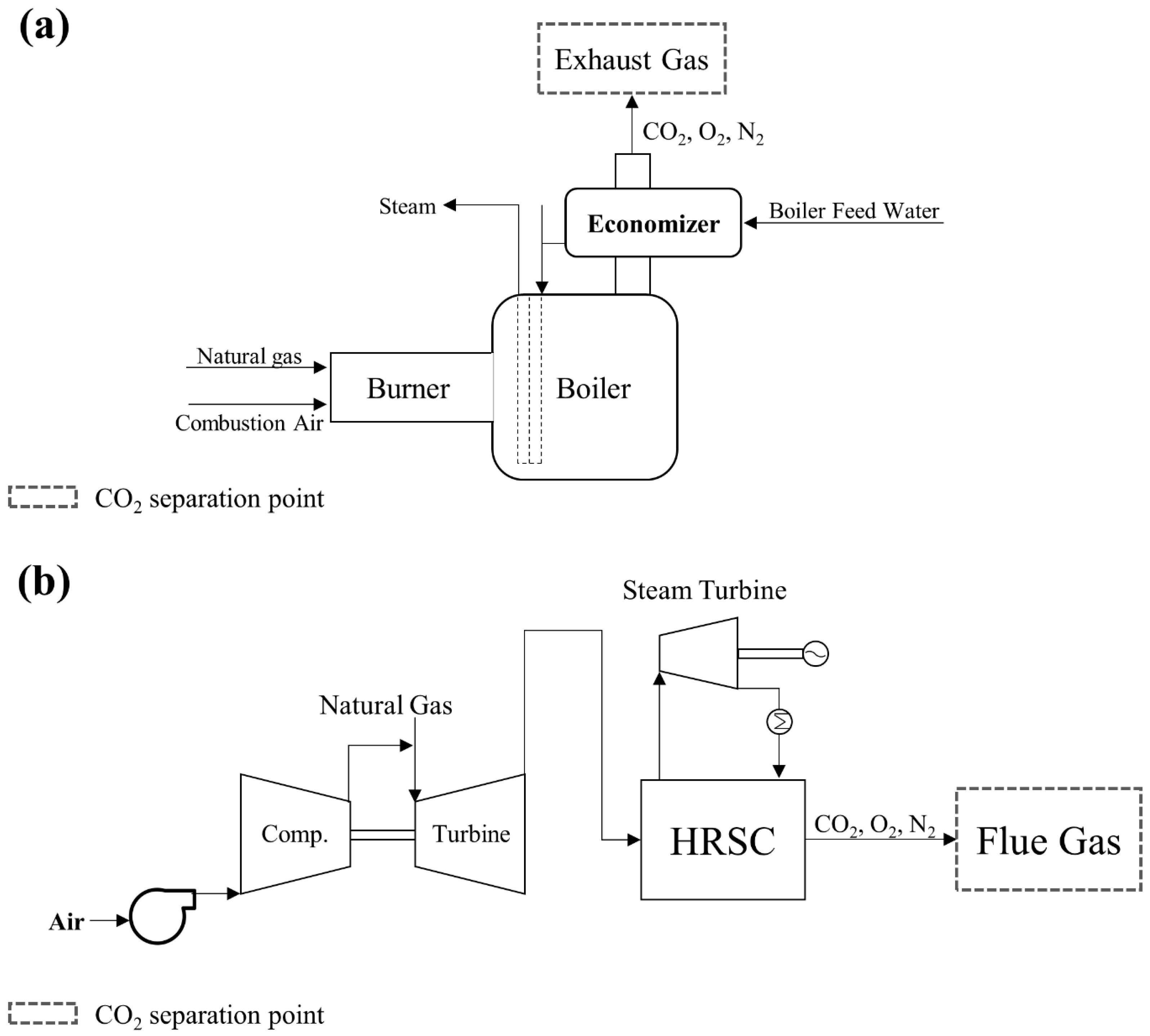
3.2.1. Natural Gas Power Plant

Natural gas power plants have emerged as promising targets for membrane-based CO2 capture due to their frequent location in urban areas, where compact system integration is essential, as well as the environmental benefits of solvent-free processes. CO2 in these systems is typically captured downstream of heat recovery steam generators (HRSGs) in NGCC units or after boiler exhaust treatment in industrial natural gas (NG) boilers (Figure 2). Although both burn natural gas, the properties of the resulting flue gas differ substantially, which significantly impacts membrane system design and performance.
In NGCC systems, the flue gas passes through a gas turbine, a steam turbine, and HRSG, resulting in low CO2 concentrations (3–4%), moderate temperatures (100–150 °C), and near-atmospheric pressure [87]. In contrast, NG boilers emit flue gas directly after combustion and heat recovery, producing higher CO2 concentrations (7–10%) and higher temperatures (150–200 °C), which are more favorable for membrane-based separation [69]. Both flue gas components include CO2, N2, H2O, O2, NOx, and SOx. Among these, acidic gases, such as NOx and SOx, as well as water vapor can adversely affect membrane performance, and therefore pretreatment steps, such as selective catalytic reduction (SCR), flue gas desulfurization (FGD), and dehumidification, may be required depending on the gas’s composition [88,89]. Therefore, pretreatment steps, such as compression, cooling, and partial impurity removal, should be implemented to ensure compatibility with membrane systems under these conditions. The following case studies illustrate how various membrane technologies have been applied to CO2 capture from NGCC and NG boiler flue gases, considering these operational constraints.
Figure 2. A schematic diagram of (a) the natural gas boiler and (b) the NGCC process (reproduced from R. W. Baker et al. [89], copyright 2017, Elsevier).
Membranes 15 00200 g002
W. Ho et al. from Ohio State University demonstrated a membrane-based CO2 capture process for NGCC flue gas at the NCCC in Wilsonville, USA [90]. Prior to field testing, the membrane’s performance was evaluated using simulated flue gas composed of CO2 (13.0%), N2 (55.4%), O2 (15.0%), H2O (16.6%), and trace levels of SO2 and NO2 (3 ppm each). Under these conditions, the system achieved a CO2 purity of 95.5% and recovery of 91.0%.
Subsequently, a field-scale test was conducted using real NGCC flue gas (CO2 8.6%, N2 86.2%, O2 5.2%, NO2 3 ppm). The feed stream, at a flow rate of 224.4 Nm3/h, was compressed to 3.5 bar and cooled to 77 °C before entering a two-stage membrane system. Consistent performance was observed, with 95.5% CO2 purity and 91.0% recovery. The system employed multilayer composite membranes incorporating polyvinylamine-based polymers and ionic liquids as CO2 carriers, configured in spiral-wound modules. Notably, the ion gel-based membranes maintained high CO2 permeance of 4200 GPU even under humid conditions. The membrane surface area was 35 m2 in the first stage and 12 m2 in the second stage.
J.-H Kim et al. from the Korea Research Institute of Chemical Technology conducted a CO2 separation experiment using simulated flue gas to generate design data for a demonstration-scale process targeting 1,000 Nm3/h of flue gas from an LNG-fired boiler [91]. The test gas consisted of CO2 (12%) and N2 (88%), with impurity removal and dehumidification assumed in the pretreatment step. A polyether sulfone (PES) hollow fiber membrane was applied in a four-stage configuration, processing a total of 41.7 Nm3/h. Operating pressures were set to 5.88/0.2 bar in the first stage and 2.94/0.98 bar in the second through fourth stages. Under these conditions, the system achieved a CO2 purity of 99% while continuously processing 30 Nm3/h of flue gas. Simulation results showed good agreement with the experimental data, confirming the validity of the model in predicting separation performance.
Y. Yang and W. Ho et al. from Ohio State University conducted a membrane-based CO2 capture test using spiral-wound modules with an effective area of 47 m2 at the NCCC [92]. Aminated TFC membranes were fabricated via roll-to-roll casting and coating using a nanoporous PES substrate and a 170 nm thick selective layer composed of poly(N-vinylformamide-co-vinylamine), polyethylene guanidine, and piperazinylethylsarcosinate. The feed gas, derived from a natural gas boiler, consisted of CO2 (8.6%), N2 (86.2%), O2 (5.2%), and 3 ppm of NO2. A sulfur dioxide polishing step was included in the pretreatment process. Under permeate pressures of 0.2–0.4 bar and temperatures ranging from 57 to 77 °C, the system achieved CO2 purity of 96.5% and recovery of 91.1%. Long-term testing over 1050 h was conducted under varying skid conditions. Throughout this period, the system maintained stable operation with CO2 recoveries of 90–99% and purities consistently above 95%. These results confirm the membrane’s durability under extended operation and support its potential for industrial-scale post-combustion CO2 capture.
R. W. Baker et al. from MTR conducted a simulation-based study evaluating the use of Selective Exhaust Gas Recirculation (S-EGR) to increase the CO2 concentration in NGCC flue gas to 15–20%, thereby enhancing membrane capture feasibility [89]. In the proposed configuration, the retentate stream from the first membrane stage was recycled, with the exhaust directed to a membrane contactor for S-EGR and the permeate stream fed back to the turbine inlet. This approach increased the CO2 concentration upstream of the membrane process without requiring major modifications to the existing NGCC system. Economic analysis showed that without S-EGR, the cost of capturing one ton of CO2 was USD 60–100 for amine-based systems and USD 55–80 for membrane-based systems. With S-EGR, these costs were reduced to USD 45–65 and USD 44–64, respectively, representing a 20–30% reduction. These findings highlight the potential of S-EGR to improve the economic viability of CO2 capture in NGCC applications, addressing one of the key limitations in post-combustion decarbonization.
Due to the low CO2 concentration (3–10%) in natural gas flue gas, the single-stage membrane process is limited to achieve both high purity and recovery without incurring excessive energy consumption. To address this limitation, membrane materials must retain high CO2 permeability and selectivity under low partial pressure conditions [93]. In parallel, multi-stage configurations incorporating recycle loops should be optimized to reduce energy penalties associated with compressors and vacuum pumps [94]. Furthermore, long-term pilot testing downstream of SCR and FGD units is essential to assess membrane fouling caused by residual NOx, SOx, and particulates and to develop effective cleaning or replacement strategies [95].

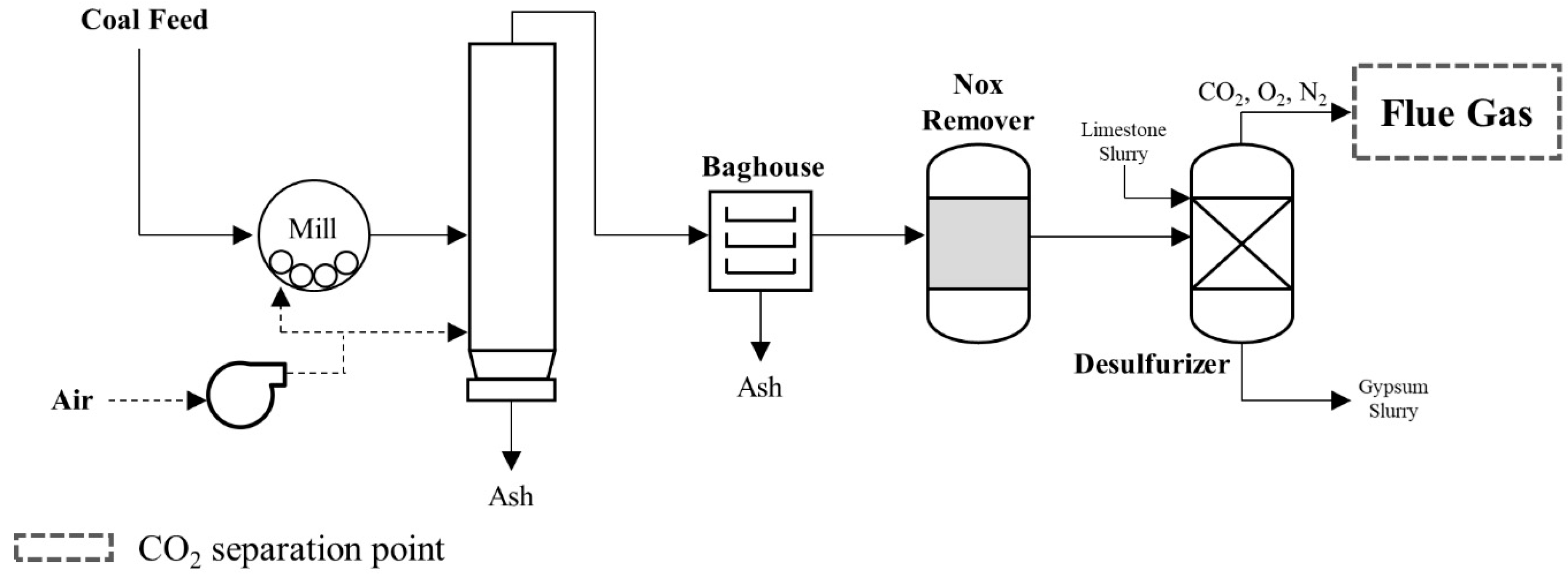
3.2.2. Coal-Fired Power Plant

In coal-fired power plants, CO2 is produced through the combustion of coal with oxygen and emitted in the flue gas from boilers or kilns (Figure 3). The typical flue gas composition includes CO2 (12–14%), N2 (67–72%), O2 (2–3%), and H2O (8–10%), along with various impurities, such as SOx, NOx, CO, and particulate matter [96,97,98]. After combustion, the gas is cooled to 120–180 °C and discharged at atmospheric pressure [99]. The presence of acidic and particulate impurities poses significant challenges for membrane stability, making the chemical resistance of membrane materials a critical requirement [82]. To ensure stable performance, flue gas pretreatment, such as FGD and SCR, is typically implemented upstream of membrane units [100,101,102].
J. Pohlmann et al. from the Karlsruhe Institute of Technology conducted a membrane-based CO2 separation test using flue gas from a hard-coal-fired power plant [104]. The flue gas composition included CO2 (14.5%), O2 (6.5%), H2O (14%), SO2 (50–100 ppm), NO (76–91 ppm), CO (4–16 ppm), and dust (5–20 mg/m3 at STP). Moisture and particulate matter were removed through pretreatment prior to membrane operation. The process employed a single-stage PolyactiveTM TFC membrane developed by Air Products operated at 80 °C. Under these conditions, the membrane system achieved CO2 purities ranging from 50% to 75% and a recovery rate of 42.7%. Notably, the system maintained stable performance for 740 h despite exposure to acidic and reducing gases. The study further emphasized the importance of robust integration with power plant control systems and the need to ensure system resilience in the event of pretreatment or compression unit failures—key considerations for industrial-scale implementation.
Ebner et al. evaluated a two-stage membrane process for CO2 capture from simulated flue gas compositions mimicking those of pulverized coal power plants [105]. The feed gas contained CO2 (15%), N2 (75%), and O2 (10%). The membrane module utilized a thin-film composite configuration with a polysulfone support layer, a polyvinylamine (PVAm) selective layer, and a polydimethylsiloxane (PDMS) protective layer, assembled into spiral-wound modules. Operated at approximately 1.3 bar and room temperature, the system was fed about 12 Nm3/h of flue gas. It achieved CO2 recovery of ~82% and product purity of ~94%. The design featured retentate recycling from the second to the first stage, enabling enhanced separation performance without significant energy penalty. In terms of economics, the estimated CO2 capture cost for this case was around USD 50/ton CO2, including compression and operating costs. This suggests that membrane systems may offer a viable alternative to amine scrubbing in post-combustion scenarios under certain integration conditions.
Alex Augustin et al. from Air Liquide Inc. developed a membrane-based CO2 capture process using polyimide-based TFC membranes designed for low-temperature operation and cost reduction [106]. The system was tested at the NCCC using flue gas from a coal-fired power plant with a composition of CO2 (13.2%), H2O (17.3%), N2 (66.4%), O2 (2.3%), Ar (0.8%), SOx (42 ppmv), and NOx (74 ppmv). The membrane operated under cryogenic conditions ranging from –30 to –45 °C, with feed pressures of 1.2–1.6 bar and permeate pressures of 0.1–0.2 bar. Under cryogenic conditions, 400 Nm3/h of flue gas was treated for 500 h, achieving a CO2 recovery of 90% and a purity of 58%. A techno-economic analysis estimated the capture cost at USD 32 per ton, confirming the cost-effectiveness and long-term stability of low-temperature membrane systems for coal-fired power plant applications.
T. Merkel et al. from MTR developed and demonstrated a membrane-based CO2 capture process for coal-fired flue gas using a 1 ton/day pilot system at the NCCC in Alabama [107]. The system treated flue gas from Plant Gaston Unit 5, which was pretreated by FGD and SCR, and operated at 45–55 °C with a feed flow rate of 250–400 Nm3/h for over 1800 h using PolarisTM membrane modules. The process achieved a CO2 purity of 40–75% and recovery of over 90% in a two-stage configuration. While high permeance was initially observed, long-term operation revealed gradual performance degradation due to membrane fouling, condensation, and structural damage, indicating the need for periodic maintenance. The study highlighted the importance of optimizing pressure and flow conditions for stable, energy-efficient operation in industrial settings.
In 2024, MTR completed a large-scale membrane-based CO2 capture system at the Wyoming Integrated Test Center, designed to treat flue gas from the Dry Fork Station, a coal-fired power plant operated by Basin Electric. The system has a capture capacity of 150 tons of CO2 per day and is integrated with a liquefaction unit, producing high-purity liquid CO2 (99.9%) at 90% recovery [108]. Building on this deployment, MTR was awarded a Front-End Engineering Design (FEED) contract by the U.S. Department of Energy for a 3 Mt/year capture facility at the same site [109]. Based on these outcomes, MTR has also initiated a membrane-based CO2 capture project for a solvent incineration facility operated by the Taiwan Semiconductor Manufacturing Company (TSMC) in Taiwan, with system deployment scheduled by the end of 2025 [110].
While recent studies have demonstrated the feasibility of membrane-based CO2 capture in coal-fired power plants, key technical and operational challenges remain. Declines in membrane permeance and selectivity due to residual impurities—despite FGD and SCR pretreatment—highlight the need for corrosion-resistant coatings and protective surface layers. In parallel, the development of highly durable membrane materials capable of maintaining stable performance under high-temperature and high-humidity conditions is essential. Finally, comprehensive techno-economic analyses and process optimization studies are required to enhance energy efficiency and reduce the overall cost of CO2 capture at industrial scale.

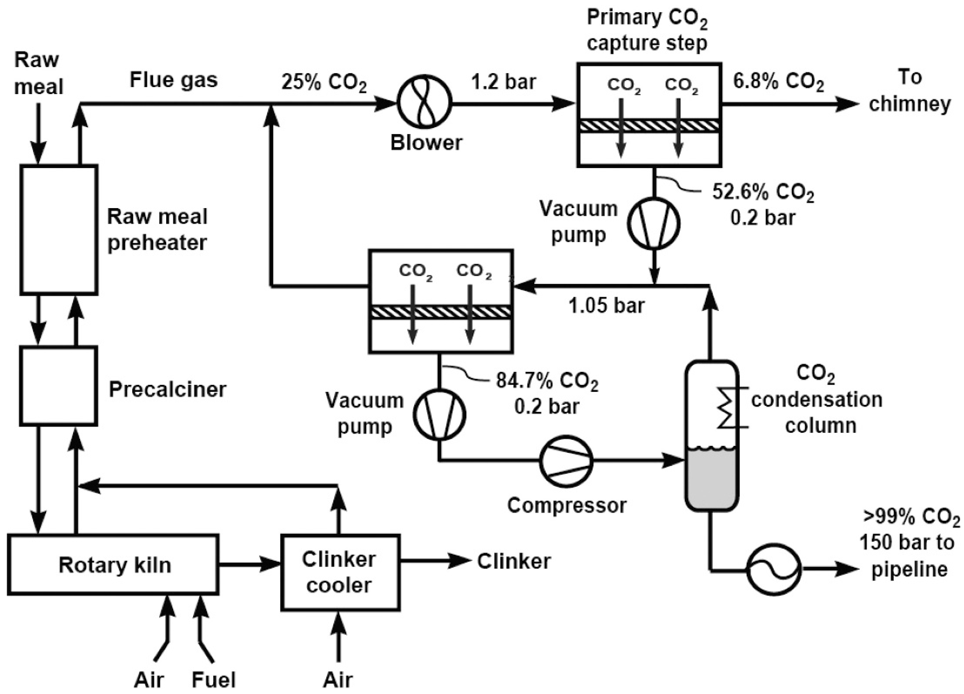
3.2.3. Cement Industry

In cement production, CO2 is primarily generated from the kiln and precalciner stages, driven by the thermal decomposition of limestone (CaCO3 → CaO + CO2) and the combustion of fossil fuels. The resulting flue gas contains CO2 (12–15%), O2 (0–21%), N2 (balance), H2O (0–15%), NOx (~500 mg/Nm3), SO2 (~50 mg/Nm3), CO (~1000 mg/Nm3), and dust (10 mg/Nm3), and it is discharged at atmospheric or slightly elevated pressure and temperatures of about 150 °C.
Compared to power plant emissions, cement kiln flue gas exhibits greater compositional complexity and variability due to its diverse raw materials and undefined fuel sources. This leads to fluctuating concentrations of acidic gases and particulates, including toxic components, which pose serious risks to membrane performance. As a result, precise and robust pretreatment systems are essential for stable long-term operation. In addition, membrane-based CO2 capture technologies must incorporate heat-resistant materials capable of withstanding thermal stress under high-temperature conditions [111,112,113,114].
R. W. Baker et al. from MTR conducted a simulation-based study on membrane CO2 capture for cement production, focusing on flue gas emitted from the rotary kiln, the precalciner, and the preheater in a facility generating 1000 tons of CO2 per day [115]. The analysis assumed prior removal of NOx and SOx through pretreatment. The simulated gas composition was CO2 (20%), O2 (4%), and N2 (64%). A two-stage membrane configuration with a total membrane area of 2780 m2 was applied, operating at 1.2/0.2 bar in the first stage and 1.05/0.2 bar in the second. Across the two stages, the CO2 concentration increased from 25% to 84.7%, enabling the recovery of approximately 80% of the plant’s total CO2 emissions. A detailed process flow diagram of the capture process is illustrated in Figure 4. This high recovery rate was achieved due to both the elevated CO2 concentration in the feed gas, which increased the separation driving force, and the use of high-performance PolarisTM membrane modules developed by MTR. The captured stream was subsequently liquefied to produce high-purity CO2, with the overall capture cost estimated at USD 43.2 per ton. These results demonstrate the strong techno-economic potential of membrane-based CO2 capture for cement industry applications.
Based on the simulation studies by MTR, T. Merkel et al. developed a preliminary engineering design for a membrane-based CO2 capture system [116]. The process was cooperated with Sargent & Lundy LLC (Chicago, IL, USA) and CEMEX Inc. (Houston, TX, USA), targeting flue gas from Kiln 2 at the CEMEX Balcones cement plant. The flue gas’s composition was CO2 (14.9%), O2 (12.1%), N2 (59.0%), and H2O (14.0%), with trace SO2 (0.37 ppmv), NOx (120 ppmv), and NO2 (12 ppmv), emitted at 132 °C and 0.99 bar at a flow rate of 587,791 m3/h. A three-stage membrane configuration was proposed, designed to capture 2247 tons of CO2 per day—equivalent to approximately 75% of Kiln 2’s emissions. The projected operational lifespan of the system was 25 years, supporting its potential for long-term industrial application. Notably, the assumption of a 25-year operational life highlights confidence in the mechanical and the chemical durability of membrane systems under real flue gas conditions. This design demonstrates long-term, full-scale integration beyond the proof-of-concept stage.
For cement kiln emissions, the same two-stage membrane process developed by Ebner et al. was applied to a simulated flue gas representative of this sector. The feed gas’s composition included CO2 (25%), 65% N2 (65%), and O2 (10%). The tests were conducted at approximately 1.3 bar and ambient temperature, using a feed flow of around 13 Nm3/h. The system achieved CO2 recovery of around 78% and a final purity of 91%. Due to the lower CO2 concentration and the larger membrane area required, the estimated capture cost was higher—approximately USD 53/ton CO2. Nevertheless, the results demonstrate that membrane systems remain a technically feasible option for cement flue gas treatment when spatial integration and modularity are prioritized.
These studies demonstrate the practical and economic potential of membrane-based CO2 capture in cement manufacturing. However, the slow progress of carbon credit systems, high capture costs, and the risk-averse nature of cement plant operations—particularly as part of critical national infrastructure—remain key barriers to commercialization. Enhancing energy efficiency through strategies like waste heat recovery and process optimization will be essential to improve the viability and accelerate the adoption of membrane technologies in the cement sector.

3.3. Iron and Steel Industry

In the steelmaking industry, blast furnace (BF) and basic oxygen furnace (BOF) processes account for approximately 70% of total sectoral CO2 emissions [117,118]. The resulting flue gas is characterized by high concentrations of both CO2 (17–25%) and CO (20–28%), along with H2 (1–5%) and N2 (50–55%), distinguishing it from other industrial streams. The CO2 capture strategy in steelmaking is generally categorized into (i) direct CO2 removal from flue gas, (ii) CO conversion via the WGS reaction followed by capture, and (iii) top gas recycling (TGR), which removes CO2 prior to recirculation. Because TGR remains at a relatively early stage of development, it is not discussed in this section. Although chemical absorption using alkanolamine solvents is currently the most commercially adopted CO2 capture method in steel plants [118], membrane-based processes remain attractive due to their potential for simpler operation, lower environmental impact, and favorable energy efficiency under moderate-pressure conditions, such as those found in BF gas streams (~3 bar). While membrane-based CCS applications in the iron and steel industry remain limited by lack of demonstration-scale results, this review draws on theoretical studies and simulation-based techno-economic analyses to assess their potential.
Ebner et al. tested flue gas from an integrated steel mill (ISM) to test the versatility of their two-stage membrane capture system. The simulated feed gas consisted of CO2 (20%), N2 (70%), and O2 (10%). The system was operated at room temperature and approximately 1.3 bar, with a feed flow rate of roughly 11 Nm3/h. Spiral-wound TFC membrane modules—comprising polysulfone, PVAm, and PDMS layers—demonstrated robust performance. The process achieved approximately 80% CO2 recovery with 95% purity. The associated CO2 capture cost was estimated at around USD 46/ton CO2, benefiting from the moderately higher CO2 concentration and the reduced specific energy demand per captured unit. These results underline the applicability of membrane-based capture in steel production environments.
R. W. Baker et al. from MTR conducted a simulation study to evaluate membrane-based CO2 capture from steelmaking flue gas, focusing on the BF–BOF route with prior removal of NOx and SOx through pretreatment [115]. The target gas, emitted from blast furnace stoves, had a flow rate of 380,000 Nm3/h and a composition of CO2 (28.5%), H2O (3.8%), O2 (2.5%), and N2 (65.2%). A two-stage membrane system using PolarisTM modules with a total area of 2780 m2 was simulated, operating at feed and permeate pressures of 1.2 and 0.2 bar, respectively, in both stages. The process achieved CO2 purity of 71% and recovery of 80%, and the captured stream was further liquefied to >99% purity via condensation at 25 bar. The estimated capture cost was USD 36.0 per ton of CO2, demonstrating strong economic viability for membrane deployment in steel manufacturing.
J.-K. Kim et al. from Hanyang University conducted a techno-economic analysis comparing membrane-based and absorption-based CO2 capture for industrial flue gas, including the steel industry [119]. Five representative flue gas streams were selected, and process simulations were performed for each case. The results showed that membrane systems become more cost-effective than absorption when the CO2 concentration exceeds 30%, while absorption remains favorable at lower concentrations. For example, in a metal production process emitting flue gas with 27.3 mol% CO2, the membrane-based capture cost was estimated at USD 41.7 per ton, highlighting its potential under specific process conditions.
The commercialization of membrane-based CO2 capture in steelmaking processes requires overcoming several technical challenges, including (i) the development of high-performance membrane materials capable of separating CO2 from CO–CO2 mixtures [120]; (ii) the optimization of energy consumption in vacuum-driven systems [121]; and (iii) increasing CO2 partial pressure at the feed side through integration with the WGS reaction [122]. In addition, membrane durability must be enhanced to tolerate elevated temperatures and acidic impurities, such as SOx and NOx, and process scalability must be demonstrated to enable the transition from pilot to full-scale industrial systems.

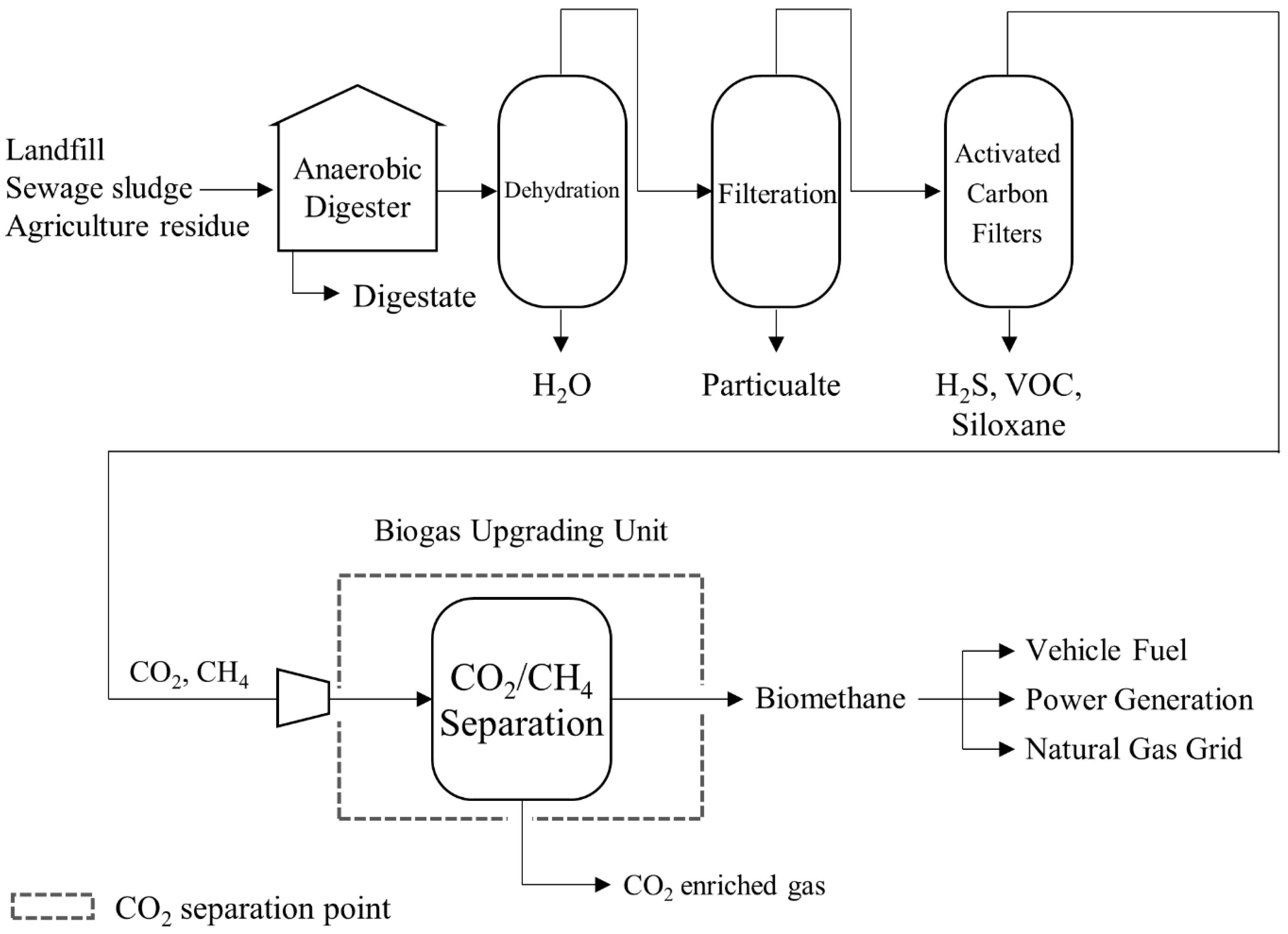
3.4. Biogas Uprading

Biogas is produced through anaerobic digestion (AD) of organic waste streams, such as agricultural residues, landfill material, sewage sludge, and wastewater. The resulting gas typically contains 30–50% CO2, which is considerably higher than in flue gas from most industrial processes. In membrane-based upgrading, biogas is compressed to 5–10 bar on the feed side, with the permeate side maintained near atmospheric pressure and operated at ambient temperatures. To withstand these conditions, mechanically robust membranes—commonly made from polysulfone or polyimide—are employed. While the exact composition of biogas varies depending on the feedstock and digestion conditions [123], it generally consists of CH4 (55–60%) and CO2 (36–40%) as major components, with trace levels of NH3, N2, O2, H2, H2S, CO, H2O, and siloxanes (Table 4) [124].
Therefore, an appropriate pretreatment process is required for the impurities’ removal, and the overall process diagram for biomethane production is shown in Figure 5.
Refined biogas can be used for heat, steam, and electricity generation or as a transportation fuel [127]. It can also be compressed into biomethane and injected into existing natural gas distribution networks. Membrane-based biogas upgrading systems have been actively demonstrated and adopted in commercial applications, particularly in Europe, with growing deployment led by companies like Evonik (SEPURAN®), Bright Renewables, and Prodeval. These implementations reflect increasing market interest and highlight the need for continued research into performance optimization and broader industrial integration.
V. Vrbová et al. from the University of Chemistry and Technology in Prague demonstrated a membrane-based biogas upgrading system at the Prague Central Wastewater Treatment Plant [123]. The feed gas consisted of CH4 (61.8%) and CO2 (37.9%), with H2S concentrations of 70–100 mg/m3 and relative humidity of 40–50%. The membrane modules used in the experiment were asymmetric hollow fiber membranes fabricated from polyimide via condensation polymerization of biphenyl tetracarboxylic dianhydride and aromatic diamines, commercially supplied by UBE Industries. The system operated at 15–25 °C and 6.0–8.0 bar. The process was designed to meet the Czech vehicle fuel standard (≥95% CH4), and it successfully achieved CH4 product purity exceeding 95%, with CO2 purity in the permeate stream reaching 96.4%. The study further emphasized the importance of pretreating H2S and water vapor to ensure membrane durability.
P. Wojnarova et al. from the Technical University of Ostrava investigated a spiral-wound polyimide-based TFC membrane system for CH4 separation from raw agro-biogas [128]. The membrane, previously shown to tolerate impurities, such as H2O, H2S, NH3, and VOCs, without pretreatment, was designed to swell in the presence of water vapor. Under these conditions, the process achieved CH4 purity levels of 95–97%, but CH4 recovery was limited to approximately 60% in a single-stage configuration [129,130,131,132]. The study highlighted the need for further research on the relationship between functional layer swelling and operating conditions to enhance the performance of low-cost membrane systems. Notably, membrane swelling was also associated with partial desulfurization of the feed gas, suggesting a dual functionality worth further exploration.
Biomethane produced through biogas upgrading can be used for energy generation—including heat, steam, and electricity—or as a transportation fuel, making it one of the most commercially viable renewable gases to date. Owing to these versatile applications, it has already been deployed in various sectors worldwide. It can also be compressed into bio-compressed natural gas (Bio-CNG) and integrated into existing natural gas distribution networks [127]. Nevertheless, broader implementation is still subject to several technical and economic constraints. These include the high cost associated with impurity removal from sludge-derived biogas, the expense of siloxane removal from landfill gas, and the substantial capital investment required for upgrading systems at wastewater treatment facilities [133,134,135].

4. Summary

This review provides a comprehensive overview of membrane-based CO2 capture technologies applied across major industrial sectors, including power generation, cement, steelmaking, and biogas upgrading. By consolidating field-tested case studies and process simulations, we analyzed how source-specific characteristics, such as CO2 concentration, gas pressure, operating temperature, and impurity composition, directly influence system configuration, membrane applicability, and process performance. For example, CO2 concentrations range from 4 to 10% in natural gas power plants to over 30% in biogas and syngas streams, while operating pressures span from atmospheric levels in post-combustion settings to as high as 50 bar in pre-combustion applications (Table 5). These variations necessitate tailored process configurations, such as multi-stage setups, recycle integration, or vacuum-assisted operation, adapted to each emission source.
While early-stage research has predominantly focused on membrane material development, our analysis underscores that actual capture performance depends equally on process-level optimization—including feed composition control, pressure ratio tuning, and pretreatment for impurities, such as SOx, NOx, and H2S. Across various sectors, pilot-scale demonstrations and simulation-based studies have shown that membrane-based CO2 capture is technically viable and holds significant potential for commercial application. Demonstrated strengths include low-temperature operation for NGCC flue gas, high-pressure compatibility with syngas and biogas, applicability to CO2-rich flue gas in the cement industry, and compact system design suitable for modular or urban-scale deployment.
Membrane-based CO2 capture, although promising for its energy efficiency and modular scalability, still faces significant engineering barriers before widespread industrial adoption can be commercialized. A major challenge includes scaling up membrane modules for high-volume flue gas streams, where achieving sufficient recovery and purity often demands multi-stage cascades. These configurations increase both capital expenditure and system complexity. Durability concerns also persist. Polymeric membranes are prone to thermal aging, plasticization, and chemical degradation when exposed to industrial flue gases containing SOx, NOx, and water vapor. While novel materials, such as ceramic or mixed-matrix membranes, offer improved resistance, their long-term performance under continuous operation remains insufficiently validated.
In addition, membrane systems require large surface areas to process low-CO2-concentration gas streams typical of post-combustion applications. This imposes spatial limitations and raises equipment and compression costs, making deployment less feasible in space-constrained environments [136,137].
To address these challenges, current research is focusing on improving membrane performance through simultaneous enhancement of selectivity and permeance, developing chemically robust materials, and standardizing module formats for ease of integration. Demonstration projects at the intermediate scale are also critical to evaluate operational stability and economic viability under realistic conditions [105,136,138,139]. It is our hope that the guidance provided in this review will contribute to overcoming existing technical limitations and advancing practical deployment across diverse emission sectors.
Table 5. Separation characteristics of various emission sources [11,12,106].
Emission SourceCO2 Conc. (%)CompositionPressure (Bar)Temperature (°C)References
Pre-combustionShifted syngas15–40CO2, H2, H2O, N2, CH4, H2S20–50250–400[75,76,77,78,79,80,140]
Post-combustionNatural gas power plant4–10CO2, N2, H2O, O2, NOx, SOxAmbient100–200[88,89,92,141]
Coal-fired power plant10–15CO2, N2, O2, H2O, CO, NOx, SOx, dustAmbient90–180[96,97,98,142,143]
Cement manufacturing5–15CO2, N2, O2, H2O, NOx, SOx, dustAmbient100–200[144,145,146]
Etc.Steel manufacturing16–42CO2, N2, CO, H21–3150–300[119,147,148]
Biogas upgrading30–45CO2, CH4, H2O, NH3, H2, O2, N2, H2S, siloxane3–740–60[124,125,149]

Author Contributions

J.W.P., investigation, writing—original draft; S.H., data curation, review and editing; J.-G.Y., funding acquisition, review and editing, project administration.; S.L., data curation, review and editing; J.-K.K., review and editing, supervision; J.H.L., data curation, supervision. All authors have read and agreed to the published version of the manuscript.

Funding

This work was supported by the Korea Environmental Industry & Technology Institute (KEITI) funded by the Ministry of Environment (MOE) (2021003390008).

Institutional Review Board Statement

Not applicable.

Data Availability Statement

No new data were created or analyzed in this study.

Conflicts of Interest

The authors declare that they have no known competing financial interests or personal relationships that could appear to have influenced the work reported in this paper.

Abbreviations

The following abbreviations are used in this manuscript:
ADAnaerobic Digestion
BFBlast Furnace
Bio-CNGBio-Compressed Natural Gas
BOFBasic Oxygen Furnace
COSCarbonyl Sulfide
FEEDFront-End Engineering Design
FGDFlue Gas Desulfurization
FTMFacilitated Transport Membrane
HRSGHeat Recovery Steam Generator
IGCCIntegrated Gasification Combined Cycle
LCOELevelized Cost of Electricity
MMMMixed-Matrix Membrane
MTRMembrane Technology Research
NCCCNational Carbon Capture Center
NGNatural Gas
NGCCNatural Gas Combined Cycle
PBIPolybenzimidazole
PDMSPolydimethylsiloxane
PESPolyether Sulfone
PVAmPolyvinylamine
SCRSelective Catalytic Reduction
S-EGRSelective Exhaust Gas Recirculation
TEATechno-Economic Analysis
TFCThin-Film Composite
TGRTop Gas Recycling
WGSWater–Gas Shift

References

  1. Hekmatmehr, H.; Esmaeili, A.; Pourmahdi, M.; Atashrouz, S.; Abedi, A.; Ali Abuswer, M.; Nedeljkovic, D.; Latifi, M.; Farag, S.; Mohaddespour, A. Carbon capture technologies: A review on technology readiness level. Fuel 2024, 363, 130898. [Google Scholar] [CrossRef]
  2. National, A.; Space, A. Atmospheric CO2 Concentrations from Mauna Loa Observatory. Available online: https://climate.nasa.gov/vital-signs/carbon-dioxide/ (accessed on 21 April 2025).
  3. Nunes, L.J.R. The Rising Threat of Atmospheric CO2: A Review on the Causes, Impacts, and Mitigation Strategies. Environments 2023, 10, 66. [Google Scholar] [CrossRef]
  4. Liu, D.; Guo, X.; Xiao, B. What causes growth of global greenhouse gas emissions? Evidence from 40 countries. Sci. Total Environ. 2019, 661, 750–766. [Google Scholar] [CrossRef] [PubMed]
  5. Gołasa, P.; Wysokiński, M.; Bieńkowska-Gołasa, W.; Gradziuk, P.; Golonko, M.; Gradziuk, B.; Siedlecka, A.; Gromada, A. Sources of Greenhouse Gas Emissions in Agriculture, with Particular Emphasis on Emissions from Energy Used. Energies 2021, 14, 3784. [Google Scholar] [CrossRef]
  6. Azhar Khan, M.; Zahir Khan, M.; Zaman, K.; Naz, L. Global estimates of energy consumption and greenhouse gas emissions. Renew. Sustain. Energy Rev. 2014, 29, 336–344. [Google Scholar] [CrossRef]
  7. Malhi, G.S.; Kaur, M.; Kaushik, P. Impact of Climate Change on Agriculture and Its Mitigation Strategies: A Review. Sustainability 2021, 13, 1318. [Google Scholar] [CrossRef]
  8. Muruganandam, M.; Rajamanickam, S.; Sivarethinamohan, S.; Gaddam, M.K.; Velusamy, P.; Gomathi, R.; Ravindiran, G.; Gurugubelli, T.R.; Muniasamy, S.K. Impact of climate change and anthropogenic activities on aquatic ecosystem—A review. Environ. Res. 2023, 238, 117233. [Google Scholar] [CrossRef]
  9. Darwin, R. Effects of Greenhouse Gas Emissions on World Agriculture, Food Consumption, and Economic Welfare. Clim. Change 2004, 66, 191–238. [Google Scholar] [CrossRef]
  10. Tovar-Ortiz, S.A.; Rodriguez-Gonzalez, P.T.; Tovar-Gómez, R. Modeling the Impact of Global Warming on Ecosystem Dynamics: A Compartmental Approach to Sustainability. World 2024, 5, 1077–1100. [Google Scholar] [CrossRef]
  11. Dai, Z.; Deng, L. Membranes for CO2 capture and separation: Progress in research and development for industrial applications. Sep. Purif. Technol. 2024, 335, 126022. [Google Scholar] [CrossRef]
  12. Hasan, M.M.F.; Baliban, R.C.; Elia, J.A.; Floudas, C.A. Modeling, Simulation, and Optimization of Postcombustion CO2 Capture for Variable Feed Concentration and Flow Rate. 1. Chemical Absorption and Membrane Processes. Ind. Eng. Chem. Res. 2012, 51, 15642–15664. [Google Scholar] [CrossRef]
  13. Wu, H.; Li, Q.; Guo, B.; Sheng, M.; Wang, D.; Mao, S.; Ye, N.; Qiao, Z.; Kang, G.; Cao, Y.; et al. Industrial-scale spiral-wound facilitated transport membrane modules for post-combustion CO2 capture: Development, investigation and optimization. J. Membr. Sci. 2023, 670, 121368. [Google Scholar] [CrossRef]
  14. Garcia, J.A.; Villen-Guzman, M.; Rodriguez-Maroto, J.M.; Paz-Garcia, J.M. Technical analysis of CO2 capture pathways and technologies. J. Environ. Chem. Eng. 2022, 10, 108470. [Google Scholar] [CrossRef]
  15. Bhown, A.S. Status and Analysis of Next Generation Post-combustion CO2 Capture Technologies. Energy Procedia 2014, 63, 542–549. [Google Scholar] [CrossRef]
  16. Bukar, A.M.; Asif, M. Technology readiness level assessment of carbon capture and storage technologies. Renew. Sustain. Energy Rev. 2024, 200, 114578. [Google Scholar] [CrossRef]
  17. Xing, L.; Chen, Z.; Zhan, G.; Huang, Z.; Wang, L.; Li, J. Efficient CO2 Desorption Catalysts: From Material Design to Kinetics Analysis and Application Evaluation. Engineering 2025, 49, 251–259. [Google Scholar] [CrossRef]
  18. Vorokhta, M.; Kusdhany, M.I.M.; Švábová, M.; Nishihara, M.; Sasaki, K.; Lyth, S.M. Hierarchically porous carbon foams coated with carbon nitride: Insights into adsorbents for pre-combustion and post-combustion CO2 separation. Sep. Purif. Technol. 2025, 354, 129054. [Google Scholar] [CrossRef]
  19. Kuppireddy, S.; Varghese, A.M.; Araj, H.A.; Hart, P.; Ramantani, T.; Bampos, G.; Karanikolos, G.N. A combined experimental and simulations assessment of CO2 capture and CO2/H2 separation performance of aminosilane-grafted MCM-41 and pore-expanded MCM-41. Microporous Mesoporous Mater. 2024, 377, 113220. [Google Scholar] [CrossRef]
  20. Zhou, T.; Wu, Z.; Wen, Y.; Dai, Z.; Song, S.; Lin, H.; Feng, X.; Lu, X.; Ji, T.; Zhu, J. Networking SiO2-Al2O3 and amines into robust and long-lasting molded sorbents for continuous CO2 capture. Chem. Eng. J. 2024, 499, 156446. [Google Scholar] [CrossRef]
  21. He, T.; Si, B.; Gundersen, T.; Lin, W.; Chen, L.; Zhang, K. High ethane content enables efficient CO2 capture from natural gas by cryogenic distillation. Sep. Purif. Technol. 2025, 352, 128153. [Google Scholar] [CrossRef]
  22. Qiao, S.; Xu, M.; Lv, X.; Zhao, H. Analysis and Optimization of Cryogenic Distillation Systems: For Reducing Distillation Energy Consumption. Chem. Eng. Technol. 2025, 48, e202400296. [Google Scholar] [CrossRef]
  23. Li, H.; Zhang, R.; Wang, T.; Sun, X.; Hou, C.; Xu, R.; Wu, Y.; Tang, Z. Simulation of H2S and CO2 removal from IGCC syngas by cryogenic distillation. Carbon Capture Sci. Technol. 2022, 3, 100012. [Google Scholar] [CrossRef]
  24. Kumar, S.; Priyadarshini, M.; Ahmad, A.; Ghangrekar, M.M. Advanced biological and non-biological technologies for carbon sequestration, wastewater treatment, and concurrent valuable recovery: A review. J. CO2 Util. 2023, 68, 102372. [Google Scholar] [CrossRef]
  25. Daneshvar, E.; Wicker, R.J.; Show, P.-L.; Bhatnagar, A. Biologically-mediated carbon capture and utilization by microalgae towards sustainable CO2 biofixation and biomass valorization—A review. Chem. Eng. J. 2022, 427, 130884. [Google Scholar] [CrossRef]
  26. Castro, M.; Gómez-Díaz, D.; Navaza, J.M.; Rumbo, A. Carbon Dioxide Capture by Chemical Solvents Based on Amino Acids: Absorption and Regeneration. Chem. Eng. Technol. 2021, 44, 248–257. [Google Scholar] [CrossRef]
  27. Liu, R.-S.; Shi, X.-D.; Wang, C.-T.; Gao, Y.-Z.; Xu, S.; Hao, G.-P.; Chen, S.; Lu, A.-H. Advances in Post-Combustion CO2 Capture by Physical Adsorption: From Materials Innovation to Separation Practice. ChemSusChem 2021, 14, 1428–1471. [Google Scholar] [CrossRef]
  28. Sun, S.; Billings, A.; Zhang, K.; Huang, K. Direct, efficient and selective capture of low concentration of CO2 from natural gas flue gas using a high temperature tubular carbon capture membrane. J. Membr. Sci. 2022, 661, 120929. [Google Scholar] [CrossRef]
  29. Shah, C.; Raut, S.; Kacha, H.; Patel, H.; Shah, M. Carbon capture using membrane-based materials and its utilization pathways. Chem. Pap. 2021, 75, 4413–4429. [Google Scholar] [CrossRef]
  30. Chen, D.; Wang, K.; Yuan, Z.; Lin, Z.; Zhang, M.; Li, Y.; Tang, J.; Liang, Z.; Li, Y.; Chen, L.; et al. Boosting membranes for CO2 capture toward industrial decarbonization. Carbon Capture Sci. Technol. 2023, 7, 100117. [Google Scholar] [CrossRef]
  31. Welton, C.; Chen, F.; Zhou, H.-C.; Yi, S. Mixed matrix membrane formation with porous metal–organic nanomaterials for CO2 capture and separation: A critical review. Carbon Capture Sci. Technol. 2025, 14, 100347. [Google Scholar] [CrossRef]
  32. Brinkmann, T.; Lillepärg, J.; Notzke, H.; Pohlmann, J.; Shishatskiy, S.; Wind, J.; Wolff, T. Development of CO2 Selective Poly(Ethylene Oxide)-Based Membranes: From Laboratory to Pilot Plant Scale. Engineering 2017, 3, 485–493. [Google Scholar] [CrossRef]
  33. Luis, P.; Van Gerven, T.; Van der Bruggen, B. Recent developments in membrane-based technologies for CO2 capture. Prog. Energy Combust. Sci. 2012, 38, 419–448. [Google Scholar] [CrossRef]
  34. Belaissaoui, B.; Le Moullec, Y.; Willson, D.; Favre, E. Hybrid membrane cryogenic process for post-combustion CO2 capture. J. Membr. Sci. 2012, 415–416, 424–434. [Google Scholar] [CrossRef]
  35. Dai, Y.; Niu, Z.; Luo, W.; Wang, Y.; Mu, P.; Li, J. A review on the recent advances in composite membranes for CO2 capture processes. Sep. Purif. Technol. 2023, 307, 122752. [Google Scholar] [CrossRef]
  36. Xu, J.; Wu, H.; Wang, Z.; Qiao, Z.; Zhao, S.; Wang, J. Recent advances on the membrane processes for CO2 separation. Chin. J. Chem. Eng. 2018, 26, 2280–2291. [Google Scholar] [CrossRef]
  37. Roussanaly, S.; Anantharaman, R. Cost-optimal CO2 capture ratio for membrane-based capture from different CO2 sources. Chem. Eng. J. 2017, 327, 618–628. [Google Scholar] [CrossRef]
  38. Xu, J.; Wang, Z.; Qiao, Z.; Wu, H.; Dong, S.; Zhao, S.; Wang, J. Post-combustion CO2 capture with membrane process: Practical membrane performance and appropriate pressure. J. Membr. Sci. 2019, 581, 195–213. [Google Scholar] [CrossRef]
  39. Asadi, J.; Kazempoor, P. Techno-economic analysis of membrane-based processes for flexible CO2 capturing from power plants. Energy Convers. Manag. 2021, 246, 114633. [Google Scholar] [CrossRef]
  40. Zhai, H.; Rubin, E.S. Techno-Economic Assessment of Polymer Membrane Systems for Postcombustion Carbon Capture at Coal-Fired Power Plants. Environ. Sci. Technol. 2013, 47, 3006–3014. [Google Scholar] [CrossRef]
  41. Li, Q.; Wu, H.; Wang, Z.; Wang, J. Analysis and optimal design of membrane processes for flue gas CO2 capture. Sep. Purif. Technol. 2022, 298, 121584. [Google Scholar] [CrossRef]
  42. Lin, H.; He, Z.; Sun, Z.; Kniep, J.; Ng, A.; Baker, R.W.; Merkel, T.C. CO2-selective membranes for hydrogen production and CO2 capture—Part II: Techno-economic analysis. J. Membr. Sci. 2015, 493, 794–806. [Google Scholar] [CrossRef]
  43. Jung, W.; Lee, J.; Lee, J.S. New facile process evaluation for membrane-based CO2 capture: Apparent selectivity model. Chem. Eng. J. 2023, 460, 141624. [Google Scholar] [CrossRef]
  44. Huang, Y.; Merkel, T.C.; Baker, R.W. Pressure ratio and its impact on membrane gas separation processes. J. Membr. Sci. 2014, 463, 33–40. [Google Scholar] [CrossRef]
  45. Russo, G.; Prpich, G.; Anthony, E.J.; Montagnaro, F.; Jurado, N.; Di Lorenzo, G.; Darabkhani, H.G. Selective-exhaust gas recirculation for CO2 capture using membrane technology. J. Membr. Sci. 2018, 549, 649–659. [Google Scholar] [CrossRef]
  46. Brunetti, A.; Scura, F.; Barbieri, G.; Drioli, E. Membrane technologies for CO2 separation. J. Membr. Sci. 2010, 359, 115–125. [Google Scholar] [CrossRef]
  47. Brunetti, A.; Drioli, E.; Lee, Y.M.; Barbieri, G. Engineering evaluation of CO2 separation by membrane gas separation systems. J. Membr. Sci. 2014, 454, 305–315. [Google Scholar] [CrossRef]
  48. Park, J.W.; Song, Y.; Lee, J.; Heo, S.; Yeo, J.-G.; Lee, C.; Han, S.; Cho, C.-H.; Kim, J.-K.; Lee, J.H. High-performance carbon dioxide capture: 99% purity and 90% recovery using a low-temperature, two-stage membrane process. J. Ind. Eng. Chem. 2024, 148, 433–444. [Google Scholar] [CrossRef]
  49. Ahmad, F.; Lau, K.K.; Shariff, A.M.; Murshid, G. Process simulation and optimal design of membrane separation system for CO2 capture from natural gas. Comput. Chem. Eng. 2012, 36, 119–128. [Google Scholar] [CrossRef]
  50. Yang, D.; Wang, Z.; Wang, J.; Wang, S. Parametric Study of the Membrane Process for Carbon Dioxide Removal from Natural Gas. Ind. Eng. Chem. Res. 2009, 48, 9013–9022. [Google Scholar] [CrossRef]
  51. Han, Y.; Ho, W.S.W. Recent advances in polymeric membranes for CO2 capture. Chin. J. Chem. Eng. 2018, 26, 2238–2254. [Google Scholar] [CrossRef]
  52. Qi, R.; Li, Z.; Zhang, H.; Fu, H.; Zhang, H.; Gao, D.; Chen, H. CO2 capture performance of ceramic membrane with superhydrophobic modification based on deposited SiO2 particles. Energy 2023, 283, 129202. [Google Scholar] [CrossRef]
  53. Fu, H.; Shen, Y.; Li, Z.; Zhang, H.; Chen, H.; Gao, D. CO2 capture using superhydrophobic ceramic membrane: Preparation and performance analysis. Energy 2023, 282, 128873. [Google Scholar] [CrossRef]
  54. Hu, L.; Clark, K.; Alebrahim, T.; Lin, H. Mixed matrix membranes for post-combustion carbon capture: From materials design to membrane engineering. J. Membr. Sci. 2022, 644, 120140. [Google Scholar] [CrossRef]
  55. Kamio, E.; Tomohisa, Y.; Matsuyama, H. Recent Advances in Carbon Dioxide Separation Membranes: A Review. J. Chem. Eng. Jpn. 2023, 56, 2222000. [Google Scholar] [CrossRef]
  56. Habib, N.; Tarhanlı, I.; Senses, E.; Keskin, S.; Uzun, A. IL-modified MOF-177 filler boosts the CO2/N2 selectivity of Pebax membrane. J. Membr. Sci. 2024, 710, 123143. [Google Scholar] [CrossRef]
  57. Abdul Samat, N.A.S.; Goh, P.S.; Lau, W.J.; Guo, Q.; Arthanareeswaran, G.; Ismail, A.F. Tailoring the properties and hydrogen separation performance of ultrathin polymethyl methacrylate composite membrane. Int. J. Hydrogen Energy 2025, 113, 749–760. [Google Scholar] [CrossRef]
  58. Ebadi Amooghin, A.; Arabi Shamsabadi, A.; Moftakhari Sharifzadeh, M.M.; Salehi, A.; Sanaeepur, H.; Dadashi Firouzjaei, M.; Rad, V.; Jafarian, H.; Elliott, M.A.; Garcia, H. Tailoring MXene composition and structure for High-Performance mixed matrix membranes in CO2 separation applications. Sep. Purif. Technol. 2025, 371, 133360. [Google Scholar] [CrossRef]
  59. Woo, K.T.; Dong, G.; Lee, J.; Kim, J.S.; Do, Y.S.; Lee, W.H.; Lee, H.S.; Lee, Y.M. Ternary mixed-gas separation for flue gas CO2 capture using high performance thermally rearranged (TR) hollow fiber membranes. J. Membr. Sci. 2016, 510, 472–480. [Google Scholar] [CrossRef]
  60. Hwang, H.Y.; Nam, S.Y.; Koh, H.C.; Ha, S.Y.; Barbieri, G.; Drioli, E. The effect of operating conditions on the performance of hollow fiber membrane modules for CO2/N2 separation. J. Ind. Eng. Chem. 2012, 18, 205–211. [Google Scholar] [CrossRef]
  61. Low, B.T.; Zhao, L.; Merkel, T.C.; Weber, M.; Stolten, D. A parametric study of the impact of membrane materials and process operating conditions on carbon capture from humidified flue gas. J. Membr. Sci. 2013, 431, 139–155. [Google Scholar] [CrossRef]
  62. Lee, S.; Kim, J.-K. Process-integrated design of a sub-ambient membrane process for CO2 removal from natural gas power plants. Appl. Energy 2020, 260, 114255. [Google Scholar] [CrossRef]
  63. Wilkes, M.D.; Ejeh, J.; Roberts, D.; Brown, S. Cost of small-scale dispatchable CO2 capture: Techno-economic comparison and case study evaluation. Int. J. Greenh. Gas Control 2023, 127, 103931. [Google Scholar] [CrossRef]
  64. Zanco, S.E.; Pérez-Calvo, J.-F.; Gasós, A.; Cordiano, B.; Becattini, V.; Mazzotti, M. Postcombustion CO2 Capture: A Comparative Techno-Economic Assessment of Three Technologies Using a Solvent, an Adsorbent, and a Membrane. ACS Eng. Au 2021, 1, 50–72. [Google Scholar] [CrossRef]
  65. Chance, R.; Chen, G.; Dai, Y.; Fan, Y.; Jones, C.; Kalyanaraman, J.; Kawajiri, Y.; Koros, W.; Lively, R.; McCool, B.; et al. Rapid Temperature Swing Adsorption using Polymeric/Supported Amine Hollow Fibers; Georgia Institute of Technology: Atlanta, GA, USA, 2015; p. 537. [Google Scholar]
  66. Ho, M.T.; Allinson, G.W.; Wiley, D.E. Reducing the Cost of CO2 Capture from Flue Gases Using Pressure Swing Adsorption. Ind. Eng. Chem. Res. 2008, 47, 4883–4890. [Google Scholar] [CrossRef]
  67. Ni, Z.; Li, S.; Zhang, X.; Bao, J.; Zhang, N. Analysis and comparison of the membrane-cryogenic hybrid process and multistage membrane process for pre-combustion carbon capture based on the superstructure method. Sep. Purif. Technol. 2025, 353, 128636. [Google Scholar] [CrossRef]
  68. Hoeger, C.; Burt, S.; Baxter, L. Cryogenic Carbon Capture™ Technoeconomic Analysis; Sustainable Energy Solutions: Orem, UT, USA, 2021. [Google Scholar]
  69. Pratiwi, V.D.; Renanto, R.; Juwari, J.; Altway, A.; Anugraha, R.P. Cost Analysis of the Performance of CO2 Separation with Various CO2 Concentrations from Gas Wells. J. Chem. Technol. Metall. 2024, 59, 935–944. [Google Scholar] [CrossRef]
  70. Wang, X.; Song, C. Carbon Capture From Flue Gas and the Atmosphere: A Perspective. Front. Energy Res. 2020, 8. [Google Scholar] [CrossRef]
  71. Rahimalimamaghani, A.; Ramezani, R.; Tanaka, D.A.P.; Gallucci, F. Carbon Molecular Sieve Membranes for Selective CO2/CH4 and CO2/N2 Separation: Experimental Study, Optimal Process Design, and Economic Analysis. Ind. Eng. Chem. Res. 2023, 62, 19116–19132. [Google Scholar] [CrossRef]
  72. Yu, M.-C.; Bai, L.-J.; Moioli, S.; Tontiwachwuthikul, P.; Plisko, T.V.; Bildyukevich, A.V.; Feng, Y.-N.; Liu, H. Hybrid CO2 capture processes consisting of membranes: A technical and techno-economic review. Adv. Membr. 2023, 3, 100071. [Google Scholar] [CrossRef]
  73. Madejski, P.; Chmiel, K.; Subramanian, N.; Kuś, T. Methods and Techniques for CO2 Capture: Review of Potential Solutions and Applications in Modern Energy Technologies. Energies 2022, 15, 887. [Google Scholar] [CrossRef]
  74. Ghasem, N. A Review of the CFD Modeling of Hydrogen Production in Catalytic Steam Reforming Reactors. Int. J. Mol. Sci. 2022, 23, 16064. [Google Scholar] [CrossRef]
  75. Wu, F.; Argyle, M.D.; Dellenback, P.A.; Fan, M. Progress in O2 separation for oxy-fuel combustion–A promising way for cost-effective CO2 capture: A review. Prog. Energy Combust. Sci. 2018, 67, 188–205. [Google Scholar] [CrossRef]
  76. Ryzhkov, A.; Bogatova, T.; Gordeev, S. Technological solutions for an advanced IGCC plant. Fuel 2018, 214, 63–72. [Google Scholar] [CrossRef]
  77. Descamps, C.; Bouallou, C.; Kanniche, M. Efficiency of an Integrated Gasification Combined Cycle (IGCC) power plant including CO2 removal. Energy 2008, 33, 874–881. [Google Scholar] [CrossRef]
  78. Field, R.P.; Brasington, R. Baseline Flowsheet Model for IGCC with Carbon Capture. Ind. Eng. Chem. Res. 2011, 50, 11306–11312. [Google Scholar] [CrossRef]
  79. Ovalle-Encinia, O.; Raupp, G.B.; Lin, J.Y.S. CO2-selective membrane reactor process for water-gas-shift reaction with CO2 capture in a coal-based IGCC power plant. Chem. Eng. Res. Des. 2024, 212, 71–80. [Google Scholar] [CrossRef]
  80. Dai, F.; Zhang, S.; Luo, Y.; Wang, K.; Liu, Y.; Ji, X. Recent Progress on Hydrogen-Rich Syngas Production from Coal Gasification. Processes 2023, 11, 1765. [Google Scholar] [CrossRef]
  81. Lin, H.; Swihart, M.; Kniep, J.; Liu, K. Sorption Enhanced Mixed Matrix Membranes for Hydrogen (H2) Purification and Carbon Dioxide (CO2) Capture; University at Buffalo: Buffalo, NY, USA, 2020; 32p. [Google Scholar]
  82. Emerson, S.; Magdefrau, N.; She, Y.; Thibaud-Erkey, C. Advanced Palladium Membrane Scale-up for Hydrogen Separation; United Technologies Corporation: Farmington, CT, USA, 2012. [Google Scholar]
  83. Krishnan, G.; Jayaweera, I.; Sanjrujo, A.; O’Brien, K.; Callahan, R.; Berchtold, K.; Roberts, D.-L.; Johnson, W. Fabrication and Scale-up of Polybenzimidazole (PBI) Membrane Based System for Precombustion-Based Capture of Carbon Dioxide; U.S. Department of Energy, National Energy Technology Laboratory: Pittsburgh, PA, USA, 2012.
  84. Kniep, J.; Salim, W.; Merkel, T.; Casillas, C.; Amo, K.; He, J.; Huang, I.; Nguyen, V.; Batoon, V. Bench-Scale Development Of A Transformative Membrane Process For Pre-Combustion CO2 Capture; Membrane Technology and Research, Inc.: Newark, CA, USA, 2022. [Google Scholar]
  85. Ovalle-Encinia, O.; Lin, J.Y.S. High-pressure CO2 permeation properties and stability of ceramic-carbonate dual-phase membranes. J. Membr. Sci. 2022, 646, 120249. [Google Scholar] [CrossRef]
  86. Zhang, K. 5—Recent progress on sulfur-resistant palladium membranes. In Current Trends and Future Developments on (Bio-) Membranes; Basile, A., Gallucci, F., Eds.; Elsevier: Amsterdam, The Netherlands, 2020; pp. 123–137. [Google Scholar]
  87. Siegelman, R.L.; Milner, P.J.; Forse, A.C.; Lee, J.-H.; Colwell, K.A.; Neaton, J.B.; Reimer, J.A.; Weston, S.C.; Long, J.R. Water Enables Efficient CO2 Capture from Natural Gas Flue Emissions in an Oxidation-Resistant Diamine-Appended Metal–Organic Framework. J. Am. Chem. Soc. 2019, 141, 13171–13186. [Google Scholar] [CrossRef]
  88. Han, Y.; Yang, Y.; Ho, W.S.W. Recent Progress in the Engineering of Polymeric Membranes for CO2 Capture from Flue Gas. Membranes 2020, 10, 365. [Google Scholar] [CrossRef]
  89. Baker, R.W.; Freeman, B.; Kniep, J.; Wei, X.; Merkel, T. CO2 capture from natural gas power plants using selective exhaust gas recycle membrane designs. Int. J. Greenh. Gas Control 2017, 66, 35–47. [Google Scholar] [CrossRef]
  90. Ho, W.S.W.; Han, Y.; Lin, L.-C. Novel Transformational Membranes and Process for CO2 Capture from Flue Gas (FE0031731); The Ohio State University: Columbus, OH, USA, 2023. [Google Scholar]
  91. Choi, S.-H.; Kim, J.-H.; Lee, Y. Pilot-scale multistage membrane process for the separation of CO2 from LNG-fired flue gas. Sep. Purif. Technol. 2013, 110, 170–180. [Google Scholar] [CrossRef]
  92. Yang, Y.; Han, Y.; Prasad, B.; Pang, R.; Zou, C.; Ho, W.S.W. Carbon capture from flue gases using an integrated membrane skid. J. Membr. Sci. 2025, 718, 123674. [Google Scholar] [CrossRef]
  93. Campanari, S.; Manzolini, G.; Chiesa, P. Using MCFC for high efficiency CO2 capture from natural gas combined cycles: Comparison of internal and external reforming. Appl. Energy 2013, 112, 772–783. [Google Scholar] [CrossRef]
  94. Zamarripa, M.A.; Eslick, J.C.; Matuszewski, M.S.; Miller, D.C. Multi-Objective Optimization of Membrane-Based CO2 Capture; National Energy Technology Laboratory (NETL): Pittsburgh, PA, USA, 2017.
  95. National Energy Technology Laboratory, Post-Combustion Membranes Technology Update; U.S. Department of Energy (DOE): Washington, DC, USA, 2013.
  96. Lee, J.-Y.; Keener, T.C.; Yang, Y.J. Potential Flue Gas Impurities in Carbon Dioxide Streams Separated from Coal-Fired Power Plants. J. Air Waste Manag. Assoc. 2009, 59, 725–732. [Google Scholar] [CrossRef] [PubMed]
  97. Wang, D.; Bao, A.; Kunc, W.; Liss, W. Coal power plant flue gas waste heat and water recovery. Appl. Energy 2012, 91, 341–348. [Google Scholar] [CrossRef]
  98. Song, C.; Pan, W.; Srimat, S.T.; Zheng, J.; Li, Y.; Wang, Y.-H.; Xu, B.-Q.; Zhu, Q.-M. Tri-reforming of Methane over Ni Catalysts for CO2 Conversion to Syngas With Desired H2/CO Ratios Using Flue Gas of Power Plants Without CO2 Separation. In Studies in Surface Science and Catalysis; Park, S.-E., Chang, J.-S., Lee, K.-W., Eds.; Elsevier: Amsterdam, The Netherlands, 2004; Volume 153, pp. 315–322. [Google Scholar]
  99. Huang, S.; Li, C.; Tan, T.; Fu, P.; Xu, G.; Yang, Y. An Improved System for Utilizing Low-Temperature Waste Heat of Flue Gas from Coal-Fired Power Plants. Entropy 2017, 19, 423. [Google Scholar] [CrossRef]
  100. Córdoba, P. Status of Flue Gas Desulphurisation (FGD) systems from coal-fired power plants: Overview of the physic-chemical control processes of wet limestone FGDs. Fuel 2015, 144, 274–286. [Google Scholar] [CrossRef]
  101. Fan, Y.; Yu, W.; Wu, A.; Shu, W.; Zhang, Y. Recent progress on CO2 separation membranes. RSC Adv. 2024, 14, 20714–20734. [Google Scholar] [CrossRef]
  102. Zhang, L.; Hu, B.; Song, H.; Yang, L.; Ba, L. Colloidal Force Study of Particle Fouling on Gas Capture Membrane. Sci. Rep. 2017, 7, 12939. [Google Scholar] [CrossRef]
  103. Adams II, T.A.; Hoseinzade, L.; Madabhushi, P.B.; Okeke, I.J. Comparison of CO2 Capture Approaches for Fossil-Based Power Generation: Review and Meta-Study. Processes 2017, 5, 44. [Google Scholar] [CrossRef]
  104. Pohlmann, J.; Bram, M.; Wilkner, K.; Brinkmann, T. Pilot scale separation of CO2 from power plant flue gases by membrane technology. Int. J. Greenh. Gas Control 2016, 53, 56–64. [Google Scholar] [CrossRef]
  105. Wu, H.; Li, Q.; Sheng, M.; Wang, Z.; Zhao, S.; Wang, J.; Mao, S.; Wang, D.; Guo, B.; Ye, N.; et al. Membrane technology for CO2 capture: From pilot-scale investigation of two-stage plant to actual system design. J. Membr. Sci. 2021, 624, 119137. [Google Scholar] [CrossRef]
  106. United States Department of Education; National Energy Technology Laboratory. Carbon Capture Technology Compendium 2022; U.S. Department of Energy, National Energy Technology Laboratory: Pittsburgh, PA, USA, 2022; pp. 264–271.
  107. Merkel, T.C.; Wei, X.; White, L.S.; Pande, S.; Wijmans, H.J.; Baker, R.W. Pilot Testing of a Membrane System for Post-Combustion CO2 Capture; U.S. Department of Energy, National Energy Technology Laboratory (NETL): Pittsburgh, PA, USA, 2016.
  108. Freeman, B. Large Pilot Testing of the MTR Membrane Post-Combution CO2 Capture Process; Membrane Technology Research Inc.: Newark, CA, USA, 2024. [Google Scholar]
  109. News, M. MTR Carbon Capture Awarded DOE Funding for Integrated CCS Demonstration Project at Dry Fork Station. Available online: https://mtrccs.com/mtr-carbon-capture-awarded-doe-funding-for-integrated-ccs-demonstration-project-at-dry-fork-station (accessed on 6 March 2024).
  110. MTR Carbon Capture Selected to Provied a Capture Plant to TSMC. Available online: https://mtrccs.com/mtr-carbon-capture-selected-to-provide-a-capture-plant-to-tsmc/ (accessed on 27 January 2025).
  111. Lindehoff, E.; Mattsson, L.; Olofsson, M.; Svensson, F.; Farnelid, H.; Legrand, C. Biomass performance and stability of 5-year outdoor microalgal cultivation for CO2 removal from cement flue gas. Bioresour. Technol. Rep. 2024, 25, 101730. [Google Scholar] [CrossRef]
  112. Zanobetti, F.; Dal Pozzo, A.; Cozzani, V. Sustainability assessment of CO2 capture across different scales of hard-to-abate emission sources. Chem. Eng. J. 2025, 505, 159466. [Google Scholar] [CrossRef]
  113. Scholes, C.A.; Ho, M.T.; Aguiar, A.A.; Wiley, D.E.; Stevens, G.W.; Kentish, S.E. Membrane gas separation processes for CO2 capture from cement kiln flue gas. Int. J. Greenh. Gas Control 2014, 24, 78–86. [Google Scholar] [CrossRef]
  114. Hassan, S.M.N.; Douglas, P.L.; Croiset, E. Techno-Economic Study of CO2 Capture from an Existing Cement Plant Using MEA Scrubbing. Int. J. Green Energy 2007, 4, 197–220. [Google Scholar] [CrossRef]
  115. Baker, R.W.; Freeman, B.; Kniep, J.; Huang, Y.I.; Merkel, T.C. CO2 Capture from Cement Plants and Steel Mills Using Membranes. Ind. Eng. Chem. Res. 2018, 57, 15963–15970. [Google Scholar] [CrossRef]
  116. Merkel, T.; Freeman, B.; Baker, R.; Hao, P.; St-Martin, P.; Pierik, D. Engineering Design of a Polaris Membrane CO2 Capture System at a Cement Plant; Membrane Technology and Research, Inc.: Newark, CA, USA, 2024. [Google Scholar]
  117. Gu, C.; Xie, J.; Li, X.; Gao, X. Levelized Cost Analysis for Blast Furnace CO2 Capture, Utilization, and Storage Retrofit in China’s Blast Furnace–Basic Oxygen Furnace Steel Plants. Energies 2023, 16, 7817. [Google Scholar] [CrossRef]
  118. Perpiñán, J.; Peña, B.; Bailera, M.; Eveloy, V.; Kannan, P.; Raj, A.; Lisbona, P.; Romeo, L.M. Integration of carbon capture technologies in blast furnace based steel making: A comprehensive and systematic review. Fuel 2023, 336, 127074. [Google Scholar] [CrossRef]
  119. Yun, S.; Jang, M.-G.; Kim, J.-K. Techno-economic assessment and comparison of absorption and membrane CO2 capture processes for iron and steel industry. Energy 2021, 229, 120778. [Google Scholar] [CrossRef]
  120. IEA Greenhouse Gas R&D Programme (IEAGHG). Challenges and Opportunities of CO2 Capture and Storage for the Iron and Steel Industry; IEA Greenhouse Gas R&D Programme (IEAGHG): Cheltenham, UK, 2012. [Google Scholar]
  121. Wang, K.; Hopkinson, D.; He, Q.; Nulwala, H.B.; Luebke, D.R. Membrane Development for CO2 Capture from Steel Manufacturing; National Energy Technology Laboratory (NETL): Pittsburgh, PA, USA, 2024.
  122. Al-Mamoori, M.A.; Lin, J.Y.S. Water-gas shift reaction in ceramic-carbonate dual-phase membrane reactor at high temperatures and pressures. Chem. Eng. J. 2022, 448, 137652. [Google Scholar] [CrossRef]
  123. Vrbová, V.; Ciahotný, K. Upgrading Biogas to Biomethane Using Membrane Separation. Energy Fuels 2017, 31, 9393–9401. [Google Scholar] [CrossRef]
  124. Chen, X.Y.; Vinh-Thang, H.; Ramirez, A.A.; Rodrigue, D.; Kaliaguine, S. Membrane gas separation technologies for biogas upgrading. RSC Adv. 2015, 5, 24399–24448. [Google Scholar] [CrossRef]
  125. Baena-Moreno, F.M.; le Saché, E.; Pastor-Pérez, L.; Reina, T.R. Membrane-based technologies for biogas upgrading: A review. Environ. Chem. Lett. 2020, 18, 1649–1658. [Google Scholar] [CrossRef]
  126. Calbry-Muzyka, A.; Madi, H.; Rüsch-Pfund, F.; Gandiglio, M.; Biollaz, S. Biogas composition from agricultural sources and organic fraction of municipal solid waste. Renew. Energy 2022, 181, 1000–1007. [Google Scholar] [CrossRef]
  127. Shin, M.S.; Jung, K.-H.; Kwag, J.-H.; Jeon, Y.-W. Biogas separation using a membrane gas separator: Focus on CO2 upgrading without CH4 loss. Process Saf. Environ. Prot. 2019, 129, 348–358. [Google Scholar] [CrossRef]
  128. Wojnarova, P.; Rusin, J.; Basinas, P.; Kostejn, M.; Nemec, J.; Stanovský, P.; Kim, A.S.; Izak, P. Unveiling the potential of composite water-swollen spiral wound membrane for design of low-cost raw biogas purification. Sep. Purif. Technol. 2023, 326, 124783. [Google Scholar] [CrossRef]
  129. Simcik, M.; Ruzicka, M.C.; Karaszova, M.; Sedlakova, Z.; Vejrazka, J.; Vesely, M.; Capek, P.; Friess, K.; Izak, P. Polyamide thin-film composite membranes for potential raw biogas purification: Experiments and modeling. Sep. Purif. Technol. 2016, 167, 163–173. [Google Scholar] [CrossRef]
  130. Suleman, M.S.; Lau, K.K.; Yeong, Y.F. Plasticization and Swelling in Polymeric Membranes in CO2 Removal from Natural Gas. Chem. Eng. Technol. 2016, 39, 1604–1616. [Google Scholar] [CrossRef]
  131. Poloncarzova, M.; Vejrazka, J.; Vesely, V.; Izak, P. Effective Purification of Biogas by a Condensing-Liquid Membrane. Angew. Chem. Int. Ed. 2011, 50, 669–671. [Google Scholar] [CrossRef]
  132. Jung, W.; Lee, J.S.; Yoon, H.; Kim, T.; Kim, Y.H. Water membrane for carbon dioxide separation. Sep. Purif. Technol. 2018, 203, 268–273. [Google Scholar] [CrossRef]
  133. Jameel, M.K.; Mustafa, M.A.; Ahmed, H.S.; Mohammed, A.j.; Ghazy, H.; Shakir, M.N.; Lawas, A.M.; Mohammed, S.k.; Idan, A.H.; Mahmoud, Z.H.; et al. Biogas: Production, properties, applications, economic and challenges: A review. Results Chem. 2024, 7, 101549. [Google Scholar] [CrossRef]
  134. Verma, P.; Samanta, S.K. Overview of Biogas Reforming Technologies for Hydrogen Production: Advantages and Challenges. In Proceedings of the First International Conference on Recent Advances in Bioenergy Research; Springer: New Delhi, India, 2016; pp. 227–243. [Google Scholar]
  135. Chuda, A.; Ziemiński, K. Challenges in Treatment of Digestate Liquid Fraction from Biogas Plant. Performance of Nitrogen Removal and Microbial Activity in Activated Sludge Process. Energies 2021, 14, 7321. [Google Scholar] [CrossRef]
  136. He, X.; Chen, D.; Liang, Z.; Yang, F. Insight and Comparison of Energy-efficient Membrane Processes for CO2 Capture from Flue Gases in Power Plant and Energy-intensive Industry. Carbon Capture Sci. Technol. 2022, 2, 100020. [Google Scholar] [CrossRef]
  137. Chen, K.K.; Salim, W.; Han, Y.; Wu, D.; Ho, W.S.W. Fabrication and scale-up of multi-leaf spiral-wound membrane modules for CO2 capture from flue gas. J. Membr. Sci. 2020, 595, 117504. [Google Scholar] [CrossRef]
  138. He, X. A review of material development in the field of carbon capture and the application of membrane-based processes in power plants and energy-intensive industries. Energy Sustain. Soc. 2018, 8, 34. [Google Scholar] [CrossRef]
  139. Mollahosseini, A.; Nikkhah Dafchahi, M.; Khoshhal Salestan, S.; Chew, J.W.; Mozafari, M.; Soroush, M.; Hrapovic, S.; Hemraz, U.D.; Giro, R.; Steiner, M.B.; et al. Polymeric membranes in carbon capture, utilization, and storage: Current trends and future directions in decarbonization of industrial flue gas and climate change mitigation. Energy Environ. Sci. 2025, 18, 5025–5092. [Google Scholar] [CrossRef]
  140. Jordal, K.; Anantharaman, R.; Peters, T.A.; Berstad, D.; Morud, J.; Nekså, P.; Bredesen, R. High-purity H2 production with CO2 capture based on coal gasification. Energy 2015, 88, 9–17. [Google Scholar] [CrossRef]
  141. Hu, Y.; Gao, Y.; Lv, H.; Xu, G.; Dong, S. A New Integration System for Natural Gas Combined Cycle Power Plants with CO2 Capture and Heat Supply. Energies 2018, 11, 3055. [Google Scholar] [CrossRef]
  142. Merkel, T.; Kniep, J.; Fulton, D.; Watson, R.; Sakib, N.; Westling, E.; Prakash, A.; Hofmann, T.; Huang, I.; Nguyen, V.; et al. Integrated Testing of a Membrane CO2 Capture Process with a Coal-Fired Boiler; Membrane Technology and Research, Inc.: Newark, CA, USA, 2018. [Google Scholar]
  143. Wang, Y.; Zhao, L.; Otto, A.; Robinius, M.; Stolten, D. A Review of Post-combustion CO2 Capture Technologies from Coal-fired Power Plants. Energy Procedia 2017, 114, 650–665. [Google Scholar] [CrossRef]
  144. Yu, H.; Guo, M.-Z.; Ling, T.-C. Carbon sequestration via CO2 curing of cement compacts: Optimizing flue gas inherent heat and water vapor. J. Ind. Eng. Chem. 2024, 137, 252–259. [Google Scholar] [CrossRef]
  145. Schakel, W.; Hung, C.R.; Tokheim, L.-A.; Strømman, A.H.; Worrell, E.; Ramírez, A. Impact of fuel selection on the environmental performance of post-combustion calcium looping applied to a cement plant. Appl. Energy 2018, 210, 75–87. [Google Scholar] [CrossRef]
  146. Barker, D.J.; Turner, S.A.; Napier-Moore, P.A.; Clark, M.; Davison, J.E. CO2 Capture in the Cement Industry. Energy Procedia 2009, 1, 87–94. [Google Scholar] [CrossRef]
  147. Kim, S.; Kim, M.; Kim, Y.T.; Kwak, G.; Kim, J. Techno-economic evaluation of the integrated polygeneration system of methanol, power and heat production from coke oven gas. Energy Convers. Manag. 2019, 182, 240–250. [Google Scholar] [CrossRef]
  148. Yang, Z.; Ding, W.; Zhang, Y.; Lu, X.; Zhang, Y.; Shen, P. Catalytic partial oxidation of coke oven gas to syngas in an oxygen permeation membrane reactor combined with NiO/MgO catalyst. Int. J. Hydrog. Energy 2010, 35, 6239–6247. [Google Scholar] [CrossRef]
  149. Rodero, M.d.R.; Muñoz, R.; González-Sánchez, A.; Ruiz, H.A.; Quijano, G. Membrane materials for biogas purification and upgrading: Fundamentals, recent advances and challenges. J. Environ. Chem. Eng. 2024, 12, 114106. [Google Scholar] [CrossRef]
Figure 1. A scheme diagram of IGCC for electricity generation using a gas turbine and the pre-combustion CO2 capture method (reproduced from P. Madejski et al. [73], copyright 2022, MDPI).
Membranes 15 00200 g001
Figure 3. A schematic diagram of a coal-fired power plant process (reproduced from T. A. Adams II et al. [103], copyright 2017, MDPI).
Membranes 15 00200 g003
Figure 4. A schematic diagram of a 1000 ton/day cement plant fitted with a membrane CO2 capture system (reproduced from R. W. Baker et al. [115], copyright 2018, American Chemical Society).
Membranes 15 00200 g004
Figure 5. A simplified process diagram of a biogas upgrading plant for biomethane production.
Membranes 15 00200 g005
Table 1. Industrial stationary CO2 emission sources [11,12].
SourcesProcessesCO2 Content (%)Traces
Power plant: pre-combustionIGCC30–45CH4, H2O, H2S, NH3
Power plant: post-combustionPetroleum power plant6–10N2
Natural gas power plant4–8NOx, SOx, O2
Coal-fired power plant10–15NOx, SOx, dust
Iron and steel industryBlast furnace20–27CO, H2, H2S
Basic oxygen furnace16–42
Cement industryPrecalciner1–30NOx, SO2, CO, dust
Calcination14–33
BiogasBiogas upgrading30–45H2O, H2, O2, N2, NH3, H2S, siloxane
Table 2. Comparison of carbon dioxide capture technologies [1,14,15,16,17,18,19,20,24,25].
MethodConceptAdvantageDisadvantage
AbsorptionDissolves CO2 using chemical solvent (e.g., amines)Effective for large-scale emission sourcesSolvent corrosion and regeneration costs
AdsorptionCaptures CO2 using porous material (e.g., zeolites, activated carbon)Regenerable adsorbentsRequires high thermal energy
Cryogenic
Separation
Liquefies CO2 at cryogenic temperature for separationProduces high-purity CO2High energy consumption
Biological
Capture
Uses microorganisms, algae, or enzymes to absorb CO2Environmentally friendlySlow absorption rate, requires large space
MembraneSeparates CO2 using selective permeation through membranesFlexible operation, low energy consumption, easy to modularizeImpurity sensitivity, limited performance at low CO2 concentrations
Table 3. Representative CO2 capture costs and application contexts by technology.
MethodCost Range
(USD/Ton CO2)
Key Factors Affecting CostPrimary ApplicationsReferences
AbsorptionUSD 44–71Solvent properties, energy requirements, plant scalePower plants, industrial
flue gas treatment
[63,64]
AdsorptionUSD 37–57Adsorbent characteristics,
regeneration method, energy penalty
Industrial point sources,
moderate CO2 concentrations
[65,66]
Cryogenic
Separation
USD 12–150Process integration,
energy efficiency, scale
High-purity CO2 streams,
industrial gas processing
[67,68,69]
Biological
Capture
USD 88–116Biomass availability,
co-product value, scale
Power generation with
negative emissions
[63,70]
MembraneUSD 42–50Compression and vacuum energy,
membrane fabrication, module costs
Post-combustion capture,
industrial flue gas
[71,72]
Table 4. Composition of various biogas sources [125,126].
ComponentAgricultural
Residue
Sewage SludgeLandfillWastewater
CH4 (%)50–7060–7035–6555–58
CO2 (%)25–4534–3830–4532–50
H2O (%)1–61–71–51–5
H2 (%)TracesTraces0–5Traces
O2 (%)0–1Traces0–1Traces
N2 (%)0–50–25–15Traces
NH3 (ppm)0–10050–1000–50–100
H2S (ppm)0–10000–4000–1000–4000
Siloxane (%)0–0.20–0.20–0.20–0.5
Disclaimer/Publisher’s Note: The statements, opinions and data contained in all publications are solely those of the individual author(s) and contributor(s) and not of MDPI and/or the editor(s). MDPI and/or the editor(s) disclaim responsibility for any injury to people or property resulting from any ideas, methods, instructions or products referred to in the content.

