Abstract
Membrane fouling remains a major obstacle to ultrafiltration. Due to their effectiveness and minimal energy demand, membranes have been extensively employed in water treatment. To improve the antifouling property of the PVDF membrane, a composite ultrafiltration membrane was created employing the in-situ embedment approach throughout the phase inversion process and utilizing a new 2D material, MAX phase Ti3ALC2. The membranes were described using FTIR (Fourier transform infrared spectroscopy), EDS (energy dispersive spectroscopy), CA (water contact angle), and porosity measurements. Additionally, atomic force microscopy (AFM), field emission scanning electron microscopy (FESEM), and energy dispersive spectroscopy (EDS) were employed. Standard flux and rejection tests were applied to study the produced membranes’ performance. Adding Ti3ALC2 reduced composite membranes’ surface roughness and hydrophobicity compared to the pristine membrane. Porosity and membrane pore size increased with the addition up to 0.3% w/v, which decreased as the additive percentage increased. The mixed matric membrane with 0.7% w/v of Ti3ALC2 (M7) had the lowest CA. The alteration in the membranes’ properties reflected well on their performance. The membrane with the highest porosity (0.1% w/v of Ti3ALC2, M1) achieved the highest pure water and protein solution fluxes of 182.5 and 148.7. The most hydrophilic membrane (M7) recorded the highest protein rejection and flux recovery ratio of 90.6, which was much higher than that of the pristine membrane, 26.2. MAX phase Ti3ALC2 is a potential material for antifouling membrane modification because of its protein permeability, improved water permeability, and outstanding antifouling characteristics.
1. Introduction
UF (ultrafiltration) technologies may effectively remove pathogens and turbidity at low pressures. Compact modular design, high water production, and excellent response to changes in water quality are all benefits of UF [1,2,3,4]. These benefits have led to the widespread use of UF membrane systems in many water treatment implementations. Polyvinylidene (PVDF) ultrafiltration membranes have received considerable attention in materials science due to their favorable properties. These properties include film formation, antioxidant activity, excellent aging resistance [5,6], high thermal and mechanical stability, and good chemical resistance [7]. The PVDF’s hydrophobic behavior, which has gained more consideration [8,9], may be addressed using membrane modification techniques such as surface modification, physical doping, or chemical grafting. Due to its simplicity, affordability, and ability to preserve the membrane’s intrinsic structure, combining nanomaterials with PVDF has become a common modification approach [10,11]. A unique hybrid PVDF-polyaniline (PANI) membrane incorporating graphene oxide (GO), for instance, was synthesized by Hifza et al. [8]. The manufactured membrane’s antifouling characteristics and solvent content were greatly enhanced by adding PANI-GO as a nanofiller. Similarly, Deng et al. [12] developed a modified blending method that incorporates the water-induced deposition of nanomaterials into PVDF phase reflection. The characterizations showed that the nanocomposite membranes were highly hydrophilic.
Recently, the field of membrane separation has garnered considerable attention for the novel family of 2D materials called “MAX phase Ti3ALC2” [13,14,15]. In order to produce MAX phase Ti3ALC2s, a form of 2D material, a layer is removed from their predecessor MAX phases. In this context, “M” refers to an early transition metal, “A” refers to a group element (often from the IVA or IIIA group), and “X” refers to carbon or nitrogen. Mn+1XnTx defines mxene Ti3C2Tx, and T stands for the functional groups (e.g., F, OH, or O). These have strong hydrophilic surfaces, electrical conductivity, a robust structure, and excellent chemical stabilities [16,17,18,19]. Separation membranes made of Ti3C2Tx have been widely applied in various applications, including gas separation, desalination, wastewater treatment, and ion sieving [20,21,22,23].
Subsequently, significant attention has been given to creating ultrafiltration membranes by incorporating carbon-based nanoparticles into polymers. These modified polymer membranes outperform standard polymer membranes regarding hydrophilicity, mechanical strength, and antifouling properties [24,25,26,27]. Han et al. [15] synthesized a novel 2D Ti3C2Tx mxene /PES composite membrane, which was shown to have superior hydrophilicity, increased water flux, and strong Congo red dye rejections. However, there are few investigations or extensive work on the MAX phase Ti3ALC2 membrane’s antifouling capabilities. In order to create a novel nanocomposite membrane with enhanced hydrophilicity and antifouling properties, MAX-phase Ti3ALC2 was inserted into the PVDF membrane in this study. The MAX-phase Ti3ALC2 nanoparticles were incorporated into the PVDF membrane using the phase inversion method. The impact of various MAX phase Ti3ALC2 concentrations on porosity, pore structure, and hydrophilicity was thoroughly assessed. The composite membranes’ water permeation, separation efficiency, morphology, and antifouling characteristics were studied.
2. Materials and Methods
2.1. Materials
Polyvinylidene fluoride (PVDF, 99.5%, 200,000 Mw, Jiangsu Frechem Co., Ltd., Nanjing, China) was used for preparing the membrane matrix. Polyvinylpyrrolidone (PVP, k30) was purchased from Sinopharm Co., Ltd., China. NMP (N-methyl-2-pyrroidone, 99.9%) was provided by Hebei Shengyuan Jinlong lmp. & EXP Co., Ltd., China. MAX phase (titanium aluminum carbide Ti3ALC2 nanoparticles, 99.95%) was obtained from Nanjing Aocheng Chemical Co., Ltd., Nanjing, China.
2.2. Membranes Preparation
A polymeric solution was prepared by adding 20% of PVDF powder and 2% of PVP powder to N-Methyl-2-pyrrolidone (NMP) with a ratio of 78%. Then, the mixture was stirred for 24 h. After that, MAX phase Ti3ALC2 was added in different proportions (see Table 1) and stirred again for 24 h. After that, the solution was sonicated for 1 h. The solution was doped on a glass plate and cast using a doctor blade knife. The membrane was submerged in a coagulation bath of distilled water. The membrane was preserved in distilled water by replacing the water every two days. Later, these membranes were treated by immersing them in propanol alcohol with a purity of 99% and a concentration of 100% for two days. Finally, the membranes were dried with air and stored for later examination, as illustrated in Figure 1.

Table 1.
Composition of the casting solution of the modified and unmodified membranes.
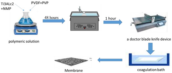
Figure 1.
Preparation process of PVDF MMMs.
2.3. Characterization
2.3.1. Characterization of Ti3C2Tx Nanoparticles
MAX PHASE Ti3ALC2 nanoparticles were qualitatively characterized by an X-ray diffractometer (Bruker D8 ADVANCE, Germany). The X-ray diffractometer was equipped with a monochromatic source of Cu Kα radiation (λ = 0.154 nm) operating from 10 to 90 at 40 mA and 40 °C. The morphology of MAX phase Ti3ALC2 nanoparticles was examined using field emission scanning electron microscopy (FE-SEM) (FEI, inspect F50, Japan).
2.3.2. Characterization of PVDF/MAX Phase Ti3ALC2 Membranes
The morphology of produced membranes was studied using the Field TESCAN VEGA3 SB FE-SEM instrument (EO, Elektronen-Optik Services GmbH, Dortmund, Germany). Cross-sections of the membranes were prepared to utilize liquid nitrogen and coated with a thin platinum layer prior to being fixed on the specimen stubs using carbon tape. EDS (energy dispersive spectroscopy, Hitachi, type S4200N, Tokyo, Japan) was utilized to obtain an elemental mapping of the membrane surface. An appropriate silicon tip and an atomic force microscope (AFM) (Multimode 8, Bruker, Germany) were employed to capture the surface topographical profile of the membranes in contact mode. The cantilever flexes due to the rise and fall of the sample topography, and the amount of this deflection can be reflected by the photodetector as up–down signals. Measurements included an assessment of the vertical variation of the membrane’s surface topography (peak–valley), the lateral force (friction forces between tip and sample, which cause the cantilever torsion and can be reflected by the photodetector’s left–right signal), and the deflection. A statistical pore size distribution was established for the outer surfaces of each membrane using the IMAGER 4.31 program. The structural modification of the membrane caused by the injection of nanoparticles was examined using FTIR (Nicolet 6700, Fourier transform infrared spectroscopy/Thermo Electrons Corp., Madison, WI, USA).
The membranes’ hydrophilicity was assessed by measuring their water contact angles. Using the sessile drop technique, the membrane contact angle was determined. This was accomplished using the CAM110 optical contact angle device (Tainan, Taiwan). Every sample was evaluated in a minimum of five various places, and an average value was considered. To find out the porosity of the membranes, the membrane samples were cut into pieces of 2 cm2 and immersed in distilled water for 15 h. Wet films were retrieved from the water. Blotting paper was utilized to collect and weigh the extra droplets from the membrane surface. The membrane was oven dried for 12 h, and samples were dry-weighed. Using Equation (1) [28], the porosity of the membrane was calculated. For every membrane sample, five porosity estimations were collected, and the computations were averaged.
In which:
Wd and Ww = the membrane’s dry and wet weight, respectively;
A = membrane area (cm2);
= water density = 1 g/cm3; and
L = thickness of the membrane (cm).
Equation (2) was used to calculate the mean pore size (rm) based on the porosity of the membrane and the flow of pure water:
In this equation:
Q = collected volume of the pure water flux per unit time (m3/s),
= water viscosity,
ε = membrane porosity,
DP = operation pressure, and
A and L are the membrane’s effective area and thickness [29].
2.4. Membrane Performance
Laboratory-scale membranes with a membrane area of 13.69 cm2 were tested for their water permeability and separation performance in a homemade dead-end filtration apparatus. In order to maintain a steady flux, each membrane was compressed with 0.2 MPa of pressure and 30 min of pure water. The water flux was then tested when the pressure was lowered to its operating pressure of 0.1 MPa. Equation (3) was used to determine the permeate flux (J) [30]:
where:
A = efficient membranes area in the filtration cell (m2), and
V = collected permeate volume (m3) at time t.
After that, a bovine serum albumin (BSA) solution of a 1000 mg/L concentration was utilized to evaluate the membrane rejection (R) using Equation (4) [27]:
where Cp and Cf are the BSA concentration in the permeate and feed solutions, respectively.
2.5. Antifouling Assessment
The solution depletion approach was used to assess the static protein adsorption onto membranes. The BSA was utilized as the model foulant. Membranes with a surface area of 13.69 cm2 were submerged in 1 g/L BSA of phosphate-buffered saline (PBS, 24 h, 25°C, 7.4 pH). Using a calibrated concentration curve, an ultraviolet spectrophotometer set to 280 nm was used to detect the concentration change before and after adsorption. The discrepancy is a representation of every membrane’s adsorption capacity. Following the water permeability and separation efficiency testing, the membrane was washed for 15 min in pure water to remove the protein that had been fouled. The water flux was then again measured in Jw (L/m2h). After that, the FRR (flux recovery ratios) were determined [31]:
where 1 and 2 denote the flux before and after cleaning.
3. Results and Discussion
3.1. Characterization of the MAX Phase Ti3ALC2
X-ray diffraction examination showed pure MAX PHASE Ti3ALC2 NPs with diffraction peaks at 19.2818°, 34.0882°, 39.1207°, 41.9004°, 48.6569°, 52.6103°, 60.6025°, 65.7535°, 70.7231°, 72.6176°, 74.1642°, 76.2845°, and 83.7989°, as depicted in Figure 2a. These peaks are typical structural peaks of Ti3ALC2. Figure 2b shows FESEM images of MAX phase Ti3ALC2 nanoparticles. It was found that MAX phase Ti3ALC2 displays a classical 2D structure.
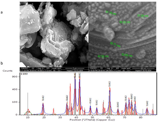
Figure 2.
MAX phase Ti3ALC2 nanoparticles: (a) FESEM images and (b) XRD spectra.
3.2. Characterization of PVDF/MAX PHASE Ti3ALC2 Membranes
The top surface and cross-section FESEM images of modified and unmodified membranes are presented in Figure 3. A thick asymmetric layer supported by multiple macro voids was found in all membranes, which showed a characteristic asymmetric skin microstructure (sub-layer). It could be noticed that the density and pore size at the top surface was improved by increasing the MAX PHASE Ti3ALC2’ load in comparison to the top surface of the neat PVDF membrane. Regarding the cross-section of FESEM images, it can be seen that two layers were obtained: one macro-void structure located near the top surface and a very thin sponge layer observed near the bottom surface. This is mainly due to the instantaneous solvent/non-solvent exchange rate throughout the fabrication of the membranes [32]. With the addition of different amounts of MAX phase Ti3ALC2, the thickness of the thin sponge layer was increased. This phenomenon is attributed to the reduction in the exchange rate of solvent/non-solvent because of the effect of the embedded MAX phase Ti3ALC2 in the PVDF casting solution on the viscosity of polymer-NPs solution [33]. Increasing the MAX PHASE Ti3ALC2 increased the casting solution’s viscosity, which delayed the diffusion of organic solvent and water during the membrane fabrication. As a result, the sponge layer in the modified membrane increased, as shown clearly in Figure 3 (membrane M8). A similar phenomenon was reported in previous research [34]. It can be concluded that the incorporation of MAX PHASE Ti3ALC2 into the PVDF membranes altered the structure of the membrane. The change in membrane porosity, as visualized by SEM images, might seem to be subtle given the qualitative nature of this technique.
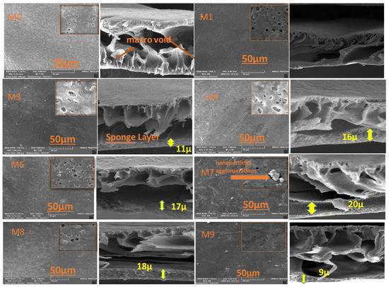
Figure 3.
SEM images of the fabricated six PVDF/Ti3ALC2 membranes: M0, M1, M3, M4, M6, M7, M8, and M9.
The brightest area in Figure 4 AFM images of the constructed membranes denotes the strongest point of the membrane surface. The valleys of membrane pores are also seen in the dark region. The average roughness (Sa), root-mean-square of the Z data (Sq), and the height variation between the tallest peak and the lowest valley (Sy) are some of the surface roughness metrics shown in Table 2. The surface roughness parameters of the composite membranes were decreased by the MAX phase Ti3ALC2 compared to the plain membrane. The nanofillers may have been consistently collocated in the membrane, which is one explanation. A smooth surface was created as a consequence of the many small peaks that occurred on the membrane surface rather than a few big ones [35,36]. To prevent foulants from penetrating the membrane pores, surface roughness must be reduced [37,38]. The PVDF- MAX PHASE Ti3ALC2 NPs’ membranes may exhibit improved antifouling capabilities as a consequence of all of these factors.
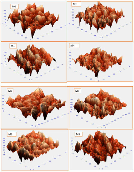
Figure 4.
AFM images and the corresponding surface roughness for the PVDF/Ti3ALC2 membranes.
Table 2.
Parameters of the membranes’ surface roughness.
The mean pore size (m) and distribution range of all membranes have also been determined using AFM (see Figure 5). The neat PVDF membrane has an 82.56 nm average pore size and a pore size distribution between 20 and 160 nm, whereas M1 has a mean pore size of 101.42 nm and a pore size distribution range of 20–130 nm. The addition of Ti3ALC2 at a low concentration (i.e., M1) increased the mean pore size and narrowed the distribution range. A further increase of Ti3ALC2 NPs led to a reduction in pore size while the pore distribution range continued to narrow. For example, the mean pore size of M3 was 84.47 nm, which was higher than M7 (59.31 nm). The increased quantity of nano-additives may improve casting solution viscosity, postpone the mixing–demixing process between the non-solvent and solvent, and bestow these reduced surface pore size palpable properties. These results agree with SEM results and experimentally measured porosity and mean pore diameters (Figure 6). All observations showed that adding Ti3ALC2 nanoparticles up to 0.3% resulted in increasing the membranes’ porosity, and further increases led to a lower porosity when the Ti3ALC2 content increased. The reduction of porosity and the mean pore size of the membrane could be attributed to the increase in polymer viscosity or membrane pore blockage caused by aggregation of the Ti3ALC2 nanoparticles [39].

Figure 5.
Pore size distribution of the modified and unmodified membranes.

Figure 6.
Mean pore size and porosity of different PVDF/Ti3ALC2 membranes.
EDX was performed to analyze and confirm the modified membranes’ elemental compositions. C was primarily derived from PVDF and MAX phase Ti3ALC2 and Ti, whereas Al was acquired from MAX phase Ti3ALC2. The contents of the spectra and elements are given in Figure 7. The presence of Ti attested to the efficient incorporation of MAX phase Ti3ALC2 into the membrane [39].
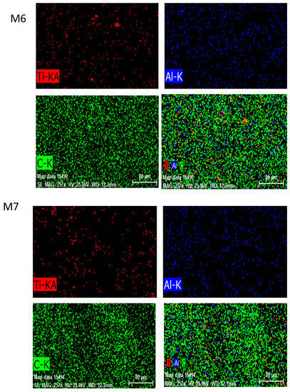
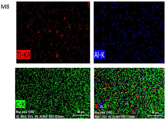
Figure 7.
The energy dispersive spectroscopy (EDS) images of MAX phase Ti3ALC2-incorporated membranes M6, M7, and M8.
The chemical behavior of the PVDF membrane was analyzed using FTIR both before and after the addition of MAX phase Ti3ALC2 nanoparticles. The results are presented in Figure 8. There is a clear increase in peak intensity at 1650, 2349, and 3767 cm−1 after adding Ti3ALC2. These peaks correspond to –C=O, –CH, and –OH groups. Recent studies also detected these peaks that synthesized pristine and composite MAX phase membranes [40,41,42]. The membrane’s spectra showed that the introduction of MAX phase Ti3ALC2 nanoparticles did not alter the features of the vibrational bands, suggesting that the membrane’s chemical composition and non-covalent interaction with MAX phase Ti3ALC2 remained unaltered.
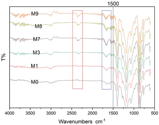
Figure 8.
FTIR spectra for modified and unmodified membranes.
Hydrophilicity is among the essential criteria for a membrane utilized for filtration and is directly associated with the membrane’s antifouling capabilities. Figure 9 illustrates the measurement of the water contact angle for all membranes. The neat PVDF membrane exhibited the greatest water contact angle of all the membranes. With the increase of MAX phase Ti3ALC2 content, the water contact angle lowered to 53.43°, which indicates the improvement in the hydrophilicity of the membranes [42]. Increasing the percentage of Ti3ALC2 beyond 0.7% results in increasing the water contact angle of the membranes. This could not be explained by surface roughness, as it decreased after increasing the number of nanoparticles added. It was noticed that the intensity of the FTIR peaks for the oxygen-containing functional groups (e.g., C=O) that normally correlate well with hydrophilicity decreased after the increasing Ti3ALC2 beyond 0.7%. When the Ti3ALC2 nanoparticles increased in the PVDF casting solution, they could agglomerate on the surface of the membrane, which, in turn, may overshadow the effect of the functional groups and their effects on membrane water affinity.
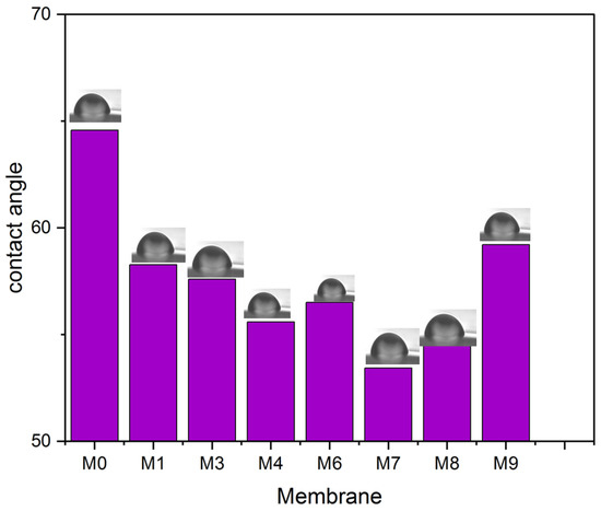
Figure 9.
Water contact angle for all PVDF/MAX PHASE Ti3ALC2 membranes.
At a pressure of 0.1 MPa, the pure water flux (PWF) was estimated. Figure 10 illustrates how the content of MAX phase Ti3ALC2 affects the performance of PVDF/MAX phase Ti3ALC2 membranes. The pure water flux of the PVDF/MAX composite Ti3ALC2 membrane rose with the addition of MAX phase Ti3ALC2 up to 0.4 w/w%; however, further increases in the concentration of the additives beyond this percentage led to an increase in the contact angle and a decrease in porosity. This change reflects well on the pure water flux of the membrane. The increase of MAX phase Ti3ALC2 beyond 0.4 w/w% may induce pore clogging of the membrane, leading to a decrease in the pure water flux [43]. As usually happens with hydrophilic additives, as reported in the literature [19,23,27], their molecules could be occluded or entrapped between the polymer chains. The same pattern was observed using a BSA solution with a small decline in the permeation flux, as shown in Figure 9. Solutes are deposited on the membrane surface and pores, causing membrane contamination and decreased flow throughout filtration [44,45]. Although membrane fouling is unavoidable, it may be mitigated to some extent by using the right solutions, such as inserting a hydrophilic substance into the membrane. Adding MAX phase Ti3ALC2 in this study enhanced the membrane’s hydrophilicity and contamination. Using bovine serum albumin (BSA) as a representative fouling agent, the antifouling capabilities of the membranes were assessed. Before and after the filtration of the BSA solution, the relative pure water flux (PWF) was computed and given as the solution recovery ratio. Figure 11 shows that the BSA rejection of neat PVDF membrane was low at about 28%, due to its hydrophobic nature, whereas with the addition of MAX PHASE Ti3ALC2, the rejection of BSA increased to a maximum of 90% [46,47].
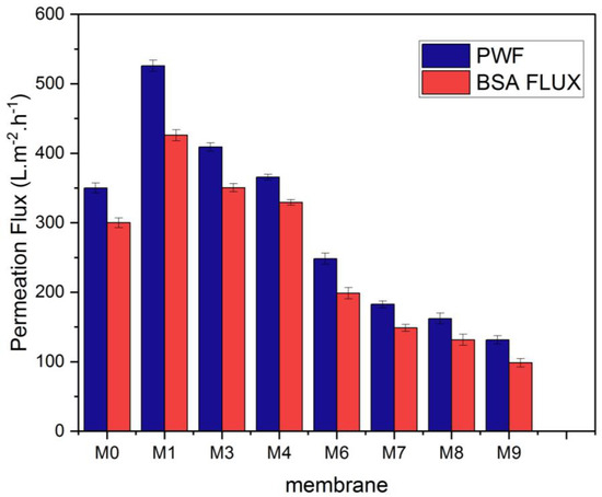
Figure 10.
Pure water and BSA (bovine serum albumin) flux of the MAX phase Ti3ALC2/(PVDF) membranes.
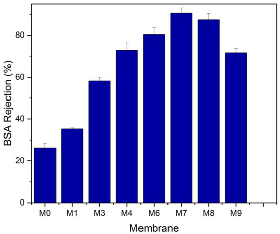
Figure 11.
Bovine serum albumin (BSA) rejection of the neat PVDF and MAX phase Ti3ALC2/PVDF membranes.
3.3. Antifouling Performance
The efficiency of separation and long-term operation are both greatly impacted by membrane fouling. Membrane fouling forms detrimental to membrane efficiency include pore blockage, concentration polarization, and cake layer formation [48]. The membrane surface hydrophobicity illustrates the PVDF membranes’ poor antifouling efficacy, despite the reasons for fouling membranes being quite complicated. An efficient and practical way to improve the antifouling capabilities of the membrane was to introduce hydrophilic MAX phase Ti3ALC2 into the membrane [49,50,51,52,53,54]. With the increasing content of MAX phase Ti3ALC2, the amount of BSA adsorbed on the surface of the composite membrane decreased with a minimum value of M6 (275 µg·cm−1). The amount of protein adsorbed reduced as affinity rose because the membrane surface shrank and there was less contact between the protein and the membrane [55,56,57,58,59,60,61].
The FRR% was determined to assess the antifouling capabilities of the membranes further, and the findings are illustrated in Figure 12. The FRR for the plain PVDF membrane was 59% lower than that of the other nanocomposite membranes. Due mainly to its increased hydrophilicity, the Membrane M7 had the greatest flux recovery ratio (84.1%). The interaction between the foulants and the membrane surface determines whether fouling is irreversible or reversible. Reversible fouling is induced by weak interactions between the membrane surface and the fouling particles, which are easily removed. It appears that most of the accumulated BSA on M7 was reversible fouling. The foulants’ attachment to the UF membrane is dictated by its rejection mechanism (molecular sieving and adsorption) and the nature of the interaction of foulants with the membrane surface (weak, physical interaction or strong, chemical bonding). Since protein adsorption onto surfaces is governed mainly by non-specific interactions such as hydrophobic–hydrophobic interaction [61], it makes sense that BSA adhesion onto the UF membrane with the highest hydrophilicity (lowest contact angle) would be the weakest. Consequently, this led to the best FRR.
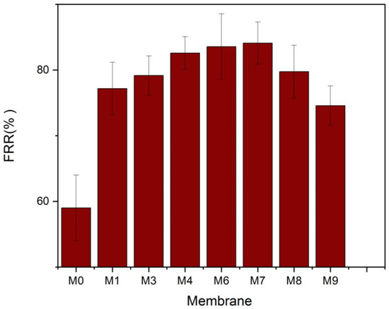
Figure 12.
Water flux recovery ratio of the MAX phase Ti3ALC2/PVDF membranes.
To assess the impact of MAX phase nanoparticles on membrane antifouling characteristics and reusability, a time-dependent flow test of the membranes was conducted. The pure water flow before and after protein filtration is shown in Figure 13. Pre-compaction of the membranes caused a modest reduction in pure water flow for all the membranes during the initial filtering stage. When the BSA solution was utilized as feed, the water flow then decreased. The membrane’s pores were then partially blocked by the BSA protein, which decreased the amount of water that could pass through the membrane. After that, deionized water was used to wash each membrane. After physical cleaning, the water flow was once again monitored to see how well the restoration process worked.
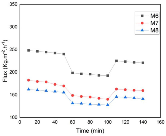
Figure 13.
Time-dependent fluctuation of BSA solution flux for M6, M7 and M8.
Table 3 shows how the results of this study were compared to those of other PVDF ultrafiltration studies that used the addition of different nanoparticles to improve antifouling properties. Due to the increased hydrophilicity brought about by the MAX membrane phase Ti3ALC2, the MAX membrane Ti3ALC2 demonstrated excellent protein rejection and water permeation efficiency.
Table 3.
Comparison of different antifouling PVDF-based membranes.
4. Conclusions
This study used composite MAX phase Ti3ALC2 to synthesize fouling-resistant PVDF membranes for UF application. Different types of Ti3ALC2 were applied to identify the nanoparticle/polymer ratio. Various advanced surface and structure chemistry analyses were employed to study and carefully track the changes brought about by the additives. The performance of the nanocomposite membranes was evaluated using pure flux and BSA reject tests. The addition of Ti3ALC2 increased membrane roughness, hydrophilicity, and mean pore diameter, reducing the pore size distribution spectrum. However, these effects occurred up to a percentage of 0.3 w/v. After, there were irregular reverse trends in these properties. This was reflected in the membrane performance, where pure water and BSA solution fluxed. As for BSA rejection and FRR, M7 recorded the best results, likely due to its high hydrophilicity compared to other membranes. The findings of this study show promising results of using Ti3ALC2 as a potential additive for reducing PVDF fouling, which merits further investigation into the performance of the produced mixed matrix membrane with complex matrix samples for long-term tests.
Author Contributions
Conceptualization, K.M.S., A.B.A. and Q.F.A.; methodology, K.M.S., A.B.A. and Q.F.A.; software, T.W.A.; validation, K.M.S., R.A.A.-J., H.S.M. and Q.F.A.; formal analysis, T.W.A.; investigation, T.W.A.; resources, T.W.A.; data curation, K.M.S., A.B.A., H.S.M. and Q.F.A.; writing—original draft preparation, K.M.S., T.W.A. and Q.F.A.; writing—review and editing K.M.S., A.B.A., R.A.A.-J. and Q.F.A.; visualization, H.S.M. and R.A.A.-J.; supervision, K.M.S., A.B.A. and Q.F.A.; project administration, H.S.M. and Q.F.A. All authors have read and agreed to the published version of the manuscript.
Funding
This research received no external funding.
Institutional Review Board Statement
Not applicable.
Data Availability Statement
Not applicable.
Conflicts of Interest
The authors declare no conflict of interest.
References
- Zularisam, A.W.; Ismail, A.F.; Salim, R. Behaviours of natural organic matter in membrane filtration for surface water treatment—A review. Desalination 2006, 194, 211–231. [Google Scholar] [CrossRef]
- Abbas, T.K.; Rashid, K.T.; Alsalhy, Q.F. NaY zeolite-polyethersulfone-modified membranes for the removal of cesium-137 from liquid radioactive waste. Chem. Eng. Res. Des. 2022, 179, 535–548. [Google Scholar] [CrossRef]
- Abdullah, R.R.; Shabeeb, K.M.; Alzubaydi, A.B.; Figoli, A.; Criscuoli, A.; Drioli, E.; Alsalhy, Q. Characterization of the Efficiency of Photo-Catalytic Ultrafiltation PES Membrane Modified with Tungsten Oxide in the Removal of Tinzaparin Sodium. Eng. Technol. J. 2022, 40, 1633–1641. [Google Scholar] [CrossRef]
- Schäfer, A.I.; Fane, A.G.; Waite, T.D. Cost factors and chemical pretreatment e_ects in the membrane filtration of waters containing natural organic matter. Water Res. 2001, 35, 1509–1517. [Google Scholar] [CrossRef]
- Abed, M.M.; Kumbharkar, S.C.; Groth, A.M.; Li, K. Economical production of PVDF-g-POEM for use as a blend in preparation of PVDF based hydrophilic hollow fibre membranes. Sep. Purif. Technol. 2013, 106, 47–55. [Google Scholar] [CrossRef]
- Malik, T.; Razzaq, H.; Razzaque, S.; Nawaz, H.; Siddiqa, A.; Siddiq, M.; Qaisar, S. Design and synthesis of polymeric membranes using water-soluble pore formers: An overview. Polym. Bull. 2018, 76, 4879–4901. [Google Scholar] [CrossRef]
- Sadiq, A.J.; Shabeeb, K.M.; Khalil, B.I.; Alsalhy, Q.F. Effect of embedding MWCNT-g-GO with PVC on the performance of PVC membranes for oily wastewater treatment, Chemical Engineering Comunications. Chem. Eng. Commun. 2019, 207, 733–750. [Google Scholar] [CrossRef]
- Yang, Y.; Zhang, H.; Wang, P.; Zheng, Q.; Li, J. The influence of nano-sized TiO2 fillers on the morphologies and properties of PSF UF membrane. J. Membr. Sci. 2007, 288, 231–238. [Google Scholar] [CrossRef]
- Ulbricht, M. Advanced functional polymer membranes. Polymer 2006, 47, 2217–2262. [Google Scholar] [CrossRef]
- Aljumaily, M.M.; Alsaadi, M.A.; Hashim, N.A.; Alsalhy, Q.F.; Rasel, D.; Mjalli, F.S. Embedded high-hydrophobic CNMs prepared by CVD technique with PVDF-co-HFP membrane for application in water desalination by DCMD. Desalination Water Treat. 2019, 142, 37–48. [Google Scholar] [CrossRef]
- Kumar, M.; Ulbricht, M. Novel antifouling positively charged hybrid ultrafiltration membranes for protein separation based on blends of carboxylated carbon nanotubes and aminated poly(arylene ether sulfone). J. Membr. Sci. 2013, 448, 62–73. [Google Scholar] [CrossRef]
- Nawaz, H.; Umar, M.; Ullah, A.; Razzaq, H.; Zia, K.M.; Liu, X. Polyvinylidene fluoride nanocomposite super hydrophilic membrane integrated with Polyaniline-Graphene oxide nano fillers for treatment of textile effluents. J. Hazard. Mater. 2020, 403, 123587. [Google Scholar] [CrossRef] [PubMed]
- Deng, W.; Li, Y. Novel superhydrophilic antifouling PVDF-BiOCl nanocomposite membranes fabricated via a modified blending-phase inversion method. Sep. Purif. Technol. 2020, 254, 117656. [Google Scholar] [CrossRef]
- Al-Araji, D.D.; Al-Ani, F.H.; Alsalhy, Q.F. Modification of polyethersulfone membranes by Polyethyleneimine (PEI) grafted Silica nanoparticles and their application for textile wastewater treatment. Environ. Technol. 2022, 1–17. [Google Scholar] [CrossRef] [PubMed]
- Liu, G.; Jin, W.; Xu, N. Two-Dimensional-Material Membranes: A New Family of High-Performance Separation Membranes. Angew. Chem. Int. Ed. Engl. 2016, 55, 13384–13397. [Google Scholar] [CrossRef]
- Zhu, X.; Tian, C.; Do-Thanh, C.L.; Dai, S. Two-Dimensional Materials as Prospective Scaffolds for Mixed-Matrix Membrane-Based CO2 Separation. Chemsuschem 2017, 10, 3304–3316. [Google Scholar] [CrossRef]
- Liu, G.; Jin, W.; Xu, N. Graphene-based membranes. Chem. Soc. Rev. 2015, 44, 5016–5030. [Google Scholar] [CrossRef] [PubMed]
- Naguib, M.; Kurtoglu, M.; Presser, V.; Lu, J.; Niu, J.; Heon, M.; Hultman, L.; Gogotsi, Y.; Barsoum, M.W. Two-dimensional nanocrystals produced by exfoliation of Ti3AlC2. Adv. Mater. 2011, 23, 4248–4253. [Google Scholar] [CrossRef] [PubMed]
- Naguib, M.; Come, J.; Dyatkin, B.; Presser, V.; Taberna, P.-L.; Simon, P.; Barsoum, M.W.; Gogotsi, Y. MAX phase Ti3ALC2: A promising transition metal carbide anode for lithium-ion batteries. Electrochem. Commun. 2012, 16, 61–64. [Google Scholar] [CrossRef]
- Feng, A.; Yu, Y.; Jiang, F.; Wang, Y.; Mi, L.; Yu, Y.; Song, L. Fabrication and thermal stability of NH4HF2-etched Ti3C2 MAX phase Ti3ALC2. Ceram. Int. 2017, 43, 6322–6328. [Google Scholar] [CrossRef]
- Han, R.; Ma, X.; Xie, Y.; Teng, D.; Zhang, S. Preparation of a new 2D MXene/PES composite membrane with excellent hydrophilicity and high flux. RSC Adv. 2017, 7, 56204–56210. [Google Scholar] [CrossRef]
- Ding, L.; Wei, Y.; Wang, Y.; Chen, H.; Caro, J.; Wang, H. A Two-Dimensional Lamellar Membrane: MXene Nanosheet Stacks. Angew. Chem. Int. Ed. Engl. 2017, 56, 1825–1829. [Google Scholar] [CrossRef] [PubMed]
- Liu, G.; Shen, J.; Liu, Q.; Liu, G.; Xiong, J.; Yang, J.; Jin, W. Ultrathin two-dimensional MXene membrane for pervaporation desalination. J. Membr. Sci. 2018, 548, 548–558. [Google Scholar] [CrossRef]
- Ren, C.E.; Hatzell, K.B.; Alhabeb, M.; Ling, Z.; Mahmoud, K.A.; Gogotsi, Y. Charge- and Size-Selective Ion Sieving through Ti3C2Tx MXene Membranes. J. Phys. Chem. Lett. 2015, 6, 4026–4031. [Google Scholar] [CrossRef] [PubMed]
- Wang, J.; Xu, Y.; Ding, B.; Chang, Z.; Zhang, X.; Yamauchi, Y.; Wu, K.C. Confined Self-Assembly in Two-Dimensional Interlayer Space: Monolayered Mesoporous Carbon Nanosheets with In-Plane Orderly Arranged Mesopores and a Highly Graphitized Framework. Angew. Chem. Int. Ed. Engl. 2018, 57, 2894–2898. [Google Scholar] [CrossRef]
- Manawi, Y.; Kochkodan, V.; Hussein, M.A.; Khaleel, M.A.; Khraisheh, M.; Hilal, N. Can carbon-based nanomaterials revolutionize membrane fabrication for water treatment and desalination? Desalination 2016, 391, 69–88. [Google Scholar] [CrossRef]
- Lee, J.; Chae, H.-R.; Won, Y.J.; Lee, K.; Lee, C.-H.; Lee, H.H.; Kim, I.-C.; Lee, J.-M. Graphene oxide nanoplatelets composite membrane with hydrophilic and antifouling properties for wastewater treatment. J. Membr. Sci. 2013, 448, 223–230. [Google Scholar] [CrossRef]
- Celik, E.; Park, H.; Choi, H.; Choi, H. Carbon nanotube blended polyethersulfone membranes for fouling control in water treatment. Water Res. 2011, 45, 274–282. [Google Scholar] [CrossRef]
- Yuliwati, E.; Ismail, A.F.; Matsuura, T.; Kassim, M.A.; Abdullah, M.S. Effect of modified PVDF hollow fiber submerged ultrafiltration membrane for refinery wastewater treatment. Desalination 2011, 283, 214–220. [Google Scholar] [CrossRef]
- Alsalhy, Q.F.; Rashid, K.T.; Ibrahim, S.S.; Ghanim, A.H.; Van der Bruggen, B.; Luis, P.; Zablouk, M. Poly(vinylidene fluoride-cohexafluropropylene) (PVDF-co-HFP) hollow fiber membranes prepared from PVDF-co-HFP/PEG-600Mw/DMAC solution for membrane distillation. J. Appl. Polym. Sci. 2013, 129, 3304–3313. [Google Scholar] [CrossRef]
- Alsalhy, Q.F.; Merza, A.S.; Rashid, K.T.; Adam, A.; Figoli, A.; Simone, S.; Drioli, E. Preparation and Characterization of poly(vinyl chloride)/poly (styrene)/poly (ethylene glycol) hollow-fiber membranes. J. Appl. Polym. Sci. 2013, 130, 989–1004. [Google Scholar] [CrossRef]
- Ali, A.M.; Rashid, K.T.; Yahya, A.A.; Majdi, H.S.; Salih, I.K.; Yusoh, K.; Figoli, A. Fabrication of Gum Arabic-Graphene (GGA) Modified Polyphenylsulfone (PPSU) Mixed Matrix Membranes: A Systematic Evaluation Study for Ultrafiltration (UF) Applications. Membranes 2021, 11, 542. [Google Scholar] [CrossRef] [PubMed]
- Vatanpour, V.; Madaeni, S.S.; Moradian, R.; Zinadini, S.; Astinchap, B. Novel antibifouling nanofiltration polyethersulfone membrane fabricated from embedding TiO2 coated multiwalled carbon nanotubes. Sep. Purif. Technol. 2012, 90, 69–82. [Google Scholar] [CrossRef]
- Hong, J.; He, Y. Polyvinylidene fluoride ultrafiltration membrane blended with nano-ZnO particle 22 for photo-catalysis self-cleaning. Desalination 2014, 332, 67–75. [Google Scholar] [CrossRef]
- Wu, G.; Nelson, M.A.; Mack, N.H.; Ma, S.; Sekhar, P.; Garzon, F.H.; Zelenay, P. Titanium dioxide-supported non-precious metal oxygen reduction electrocatalyst. Chem. Commun. 2010, 46, 7489–7491. [Google Scholar] [CrossRef]
- Anandan, S.; Rao, T.N.; Sathish, M.; Rangappa, D.; Honma, I.; Miyauchi, M. Superhydrophilic graphene-loaded TiO2 thin film for self-cleaning applications, ACS Appl. Mater. Interfaces 2012, 5, 207–212. [Google Scholar] [CrossRef]
- Chen, Y.; Huang, W.; He, D.; Situ, Y.; Huang, H. Construction of heterostructured g-C3N4/Ag/TiO2 microspheres with enhanced photocatalysis performance under visible-light irradiation. ACS Appl. Mater. Interfaces 2014, 6, 14405–14414. [Google Scholar] [CrossRef]
- Li, Y.; Zhu, L.; Guo, Y.; Song, H.; Lou, Z.; Ye, Z. A new type of hybrid nanostructure: Complete photo-generated carrier separation and ultrahigh photocatalytic activity. J. Mater. Chem. A 2014, 2, 14245–14250. [Google Scholar] [CrossRef]
- Guan, W.; Yang, X.; Dong, C.; Yan, X.; Zheng, W.; Xi, Y.; Ruan, X.; Dai, Y.; He, G. Prestructured MXene fillers with uniform channels to enhance CO2 selective permeation in mixed matrix membranes. J. Appl. Polym. Sci. 2020, 138, e49895. [Google Scholar] [CrossRef]
- Hu, J.; Zhan, Y.; Zhang, G.; Feng, Q.; Yang, W.; Chiao, Y.-H.; Zhang, S.; Sun, A. Durable and super-hydrophilic/underwater super-oleophobic two-dimensional MXene composite lamellar membrane with photocatalytic self-cleaning property for efficient oil/water separation in harsh environments. J. Membr. Sci. 2021, 637, 119627. [Google Scholar] [CrossRef]
- Khan, A.; Sherazi, T.A.; Khan, Y.; Li, S.; Naqvi, S.A.R.; Cui, Z. Fabrication and characterization of polysulfone/modified nanocarbon black composite antifouling ultrafiltration membranes. J. Membr. Sci. 2018, 554, 71–82. [Google Scholar] [CrossRef]
- Feng, L.; Zhang, Z.; Mai, Z.; Ma, Y.; Liu, B.; Jiang, L.; Zhu, D. A Super-Hydrophobic and Super-Oleophilic Coating Mesh Film for the Separation of Oil and Water. Angew. Chem. 2004, 116, 2046–2048. [Google Scholar] [CrossRef]
- Sun, D.; Liu, M.Q.; Guo, J.H.; Zhang, J.Y.; Li, B.B.; Li, D.Y. Preparation and characterization of PDMS-PVDF hydrophobic microporous membrane for membrane distillation. Desalination 2015, 370, 63–71. [Google Scholar] [CrossRef]
- Haberkamp, J.; Ernst, M.; Makdissy, G.; Huck, P.M.; Jekel, M. Protein fouling of ultrafiltration membranes—Investigation of several factors relevant for tertiary wastewater treatment. J. Environ. Eng. Sci. 2008, 7, 651–660. [Google Scholar] [CrossRef]
- Gul, S.; Rehan, Z.A.; Khan, S.A.; Akhtar, K.; Khan, M.A.; Khan, M.I.; Rashid, M.I.; Asiri, A.M.; Khan, S.B. Antibacterial PES-CA-Ag2O nanocomposite supported Cu nanoparticles membrane toward ultrafiltration, BSA rejection and reduction of nitrophenol. J. Mol. Liq. 2017, 230, 616–624. [Google Scholar] [CrossRef]
- Fane, A.G.; Fell, C.J.D. Review of fouling and fouling control in ultrafiltration. Desalination 1987, 62, 117–136. [Google Scholar] [CrossRef]
- Koo, C.H.; Mohammad, A.W.; Suja’, F.; Talib, M.Z.M. Review of the effect of selected physicochemical factors on membrane fouling propensity based on fouling indices. Desalination 2012, 287, 167–177. [Google Scholar] [CrossRef]
- Ng, L.Y.; Mohammad, A.W.; Leo, C.P.; Hilal, N. Polymeric membranes incorporated with metal/metal oxide nanoparticles: A comprehensive review. Desalination 2013, 308, 15–33. [Google Scholar] [CrossRef]
- Lang, W.-Z.; Shen, J.-P.; Zhang, Y.-X.; Yu, Y.-H.; Guo, Y.-J.; Liu, C.-X. Preparation and characterizations of charged poly(vinyl butyral) hollow fiber ultrafiltration membranes with perfluorosulfonic acid as additive. J. Membr. Sci. 2013, 430, 1–10. [Google Scholar] [CrossRef]
- Xu, H.-P.; Lang, W.-Z.; Yan, X.; Zhang, X.; Guo, Y.-J. Preparation and characterizations of poly(vinylidene fluoride)/oxidized multi-wall carbon nanotube membranes with bi-continuous structure by thermally induced phase separation method. J. Membr. Sci. 2014, 467, 142–152. [Google Scholar] [CrossRef]
- Yang, Y.; Wang, P.; Zheng, Q. Preparation and properties of polysulfone/TiO2 composite ultrafiltration membranes. J. Polym. Sci. Part B Polym. Phys. 2006, 44, 879–887. [Google Scholar] [CrossRef]
- Li, X.; Fang, X.; Pang, R.; Li, J.; Sun, X.; Shen, J.; Han, W.; Wang, L. Self-assembly of TiO2 nanoparticles around the pores of PES ultrafiltration membrane for mitigating organic fouling. J. Membr. Sci. 2014, 467, 226–235. [Google Scholar] [CrossRef]
- Xu, Z.; Zhang, J.; Shan, M.; Li, Y.; Li, B.; Niu, J.; Zhou, B.; Qian, X. Organosilane-functionalized graphene oxide for enhanced antifouling and mechanical properties of polyvinylidene fluoride ultrafiltration membranes. J. Membr. Sci. 2014, 458, 1–13. [Google Scholar] [CrossRef]
- Shi, C.; Chen, L.; Xu, Z.; Jiao, Y.; Li, Y.; Wang, C.; Shan, M.; Wang, Z.; Guo, Q. Monitoring influence 26 of chemical preparation procedure on the structure of graphene nanosheets. Phys. E 2012, 44, 1420–1424. [Google Scholar] [CrossRef]
- Zhang, S.; Wang, R.; Zhang, S.; Li, G.; Zhang, Y. Treatment of wastewater containing oil using phosphorylated silica nanotubes (PSNTs)/polyvinylidene fluoride (PVDF) composite membrane. Desalination 2014, 332, 109–116. [Google Scholar] [CrossRef]
- Huang, Z.-Q.; Zheng, F.; Zhang, Z.; Xu, H.-T.; Zhou, K.-M. The performance of the PVDF-Fe3O4 ultrafiltration membrane and the effect of a parallel magnetic field used during the membrane formation. Desalination 2012, 292, 64–72. [Google Scholar] [CrossRef]
- Safarpour, M.; Khataee, A.; Vatanpour, V. Effect of reduced graphene oxide/TiO2 nanocomposite with different molar ratios on the performance of PVDF ultrafiltration membranes. Sep. Purif. Technol. 2015, 140, 32–42. [Google Scholar] [CrossRef]
- Xu, Z.; Wu, T.; Shi, J.; Teng, K.; Wang, W.; Ma, M.; Li, J.; Qian, X.; Li, C.; Fan, J. Photocatalytic antifouling PVDF ultrafiltration membranes based on synergy of graphene oxide and TiO2 for water treatment. J. Membr. Sci. 2016, 520, 281–293. [Google Scholar] [CrossRef]
- Ma, J.; Low, J.; Wu, D.; Gong, W.; Liu, H.; Liu, D.; Long, R.; Xiong, Y. Cu and Si Co-Doping on TiO2 Nanosheets to Modulate Reactive Oxygen Species for Efficient Photocatalytic Methane Conversion. Nanoscale Horiz. 2023, 8, 63–68. [Google Scholar] [CrossRef]
- Zhang, W.; Fu, C.; Low, J.; Duan, D.; Ma, J.; Jiang, W.; Chen, Y.; Liu, H.; Qi, Z.; Long, R.; et al. High-Performance Photocatalytic Nonoxidative Conversion of Methane to Ethane and Hydrogen by Heteroatoms-Engineered TiO2. Nat. Commun. 2022, 13, 2806. [Google Scholar] [CrossRef]
- Singh, T.; Rühe, J.; Biesalski, M. Biocompatibility of Microsystems. In Reference Module in Materials Science and Materials Engineering; Elsevier: Amsterdam, The Netherlands, 2016. [Google Scholar] [CrossRef]
Disclaimer/Publisher’s Note: The statements, opinions and data contained in all publications are solely those of the individual author(s) and contributor(s) and not of MDPI and/or the editor(s). MDPI and/or the editor(s) disclaim responsibility for any injury to people or property resulting from any ideas, methods, instructions or products referred to in the content. |
© 2023 by the authors. Licensee MDPI, Basel, Switzerland. This article is an open access article distributed under the terms and conditions of the Creative Commons Attribution (CC BY) license (https://creativecommons.org/licenses/by/4.0/).