Abstract
A numerical study was conducted to investigate the effect of rotating patterned disks on the flow and permeate flux in a dynamic filtration (DF) system. The DF system consists of a rotating patterned disk and a stationary housing with a circular flat membrane. The feed flow is driven by the rotating disk with the angular velocity ranging from 200 to 1000 rpm and the applied pressure difference between inlet and outlet ports. Wheel-shaped patterns are engraved on the disk surfaces to add perturbation to the flow field and improve the permeate flux in the filtration system. Five disks with varying numbers of patterns were used in numerical simulations to examine the effects of the number of patterns and the angular velocity of the disk on the flow and permeate flux in the DF system. The flow characteristics are studied using the velocity profiles, the cross-sectional velocity vectors, the vortex structures, and the shear stress distribution. The wheel-shaped patterns shift the central core layer in the circumferential velocity profile towards the membrane, leading to higher shear stresses at the membrane and higher flux compared to a plain disk. When the number of patterns on the disk exceeded eight at a fixed Reynolds number, there were significant increases in wall shear stress and permeate flux compared to a plain disk filtration system with no pattern.
1. Introduction
Membrane filtration is a crucial process in a variety of industries, including the biotechnological, chemical, food, and pharmaceutical industries. In pressure-driven membrane filtration processes, several types of membrane modules are used in such industries: tubular modules, flat-sheet modules, hollow fiber modules, and spiral-wound modules [1]. The typical feed flow in such modules is parallel to membrane surfaces and the permeate flow, directed perpendicular to the membrane surface, is produced by the transmembrane pressure difference. Thus, the flow near the membrane surface leads to the accumulation of foulants and the formation of concentration boundary layer near the surface, which are called membrane fouling and concentration polarization, respectively. Fouling is caused by the particles contained in the feed solution that block membrane pores, and creates a cake layer due to deposited particles on the membrane surface. Concentration polarization (CP) refers to a phenomenon in which the species concentration rapidly increases within a boundary layer close to the membrane surface due to the selective transport of species through the membrane [2,3,4,5,6]. Both fouling and concentration polarization leading to a decline in the filtration performance and lifespan of a membrane module are critical issues that should be overcome or alleviated in most filtration processes [7,8,9].
Hydrodynamic control of membrane fouling (or concentration polarization) is an option to minimize fouling and achieve enhanced filtration performance. Flow control in crossflow filtration (CFF) involves either a patterned surface morphology or a static mixer [10,11,12], whereas hydrodynamic control of membrane fouling in spiral-wound modules (SWMs) is usually improved by carefully designed feed spacers [13,14,15,16]. Additionally, an optimized feed channel for a spiral-wound membrane filtration can enhance mass transfer, reduce membrane scaling, and increase flux in the reverse osmosis process [14]. To mitigate fouling or concentration polarization in a filtration system, a rotating disk or rotor blade can be adopted. The flows induced by these rotating parts increase the shear stresses on the membrane surface, promoting back transport of foulants via the rotating flows [17,18,19,20,21,22,23,24]. In addition, a rotating disk over a membrane can effectively enhance mass transfer by promoting mixing near the membrane surface. This type of filtration, which utilizes moving parts to generate a unique flow pattern resulting in enhanced filtration performance, is known as dynamic filtration (DF).
Extensive research has been carried out on DF systems since the late 1980s. Kroner and Nissinen [17] proposed a dynamic filtration module creating Taylor vortices in an annular gap by use of an axially rotating filter. They found that the rotating filtration module resulted in a better performance compared with crossflow filtration modules. Holeschovsky and Cooney [18] developed a CP model for a rotary filtration module with a rotating membrane and a stationary outer cylinder, demonstrating a superior performance of their module compared with crossflow filtration modules. Lee et al. [19] conducted an experimental study on the cell harvest using a rotating disk filtration system. The rotating speed of the disk was found to be the most critical parameter determining shear rates, flow patterns, and the bioseparation performance. The flux increased with the disk rotating speed, but at the expense of additional power input and heat dissipation. Ding et al. [20] investigated the performance of a multishaft disk (MSD) system with ceramic membrane disks mounted on two rotating shafts surrounded by a stationary housing, especially at high speed and with concentrated suspensions. As a sequel to [20], He et al. [21] subsequently conducted an experimental study on a modification of the MSD, where disks of one shaft were replaced by non-permeating metal disks rotating at a different speed to that of the membrane disks. The permeate flux was more influenced by the rotation speed of the membrane disk than that of the metal disks. In addition, disks with vanes resulted in a higher permeate flux and a lower energy consumption compared with those from smooth disks. Recently, Chaudhuri et al. extensively investigated changes of fouling, cake resistance, and concentration polarization for roto-dynamic reverse osmosis filtration systems [22,23,24]. As for a comprehensive review on dynamic filtration, one may refer to two papers by Jaffrin [25,26] and a recent paper by Cheng et al. [27].
From the viewpoint of hydrodynamics in a DF system, the enhanced filtration performance is due to a specific rotating flow pattern in the filtration system [26]. The velocity field near the membrane and the resulting shear stress distribution on the membrane are important factors, with influences on the flux decline caused by membrane fouling or concentration polarization. In this regard, a systematic numerical approach employing computational fluid dynamics (CFD) is widely used in dynamic filtration to obtain the in-depth flow field, the shear stresses, and the solute concentration near the membrane, which are influenced by the disk shape, the disk rotating speed, the operating pressure, etc. [28,29,30,31,32]. The flow in the previous numerical studies belongs to a laminar [29,30] or turbulent flow regime [31,32], depending on the material properties of the feed, the rotating speed of the disk, and the geometrical parameters of a specific dynamic filtration system. The flow regime is described by dimensionless numbers such as the Reynolds number (Re) and the aspect ratio () in a rotating system, which will be discussed in Section 2. In this study, our focus is on a rotor-stator-type dynamic filtration system. The system is composed of a rotating patterned disk and a stationary housing with a circular flat membrane.
Rotating-disk systems, on which our filtration system is based, are widely used in various applications such as turbomachinery, computer hard disk drives, automotive brake systems, medical equipment, membrane filtration systems, etc. [33]. The main concern of such applications from the viewpoint of fluid mechanics is the interaction between a spinning disk and the fluid adjacent to the disk, creating complicated three-dimensional rotating flows as observed in a rotor-stator system composed of a spinning disk and a close-fitting stationary housing [34]. Since the pioneering work of Ekman in 1905 [35], tremendous research efforts have been made to understand the in-depth flow characteristics due to a rotating disk [36,37,38,39,40]. Especially with regard to the flow in a closed rotor-stator cavity, Daily and Nece [41] performed experimental and theoretical studies and found the existence of four flow regimes according to Re and . Chew and co-workers [42,43] conducted an early numerical study on the flow inside a rotor-stator cavity with a centrifugal throughflow.
In fluids engineering applications, patterned surfaces are used as a means to add perturbations to a flow field or to guide a flow to a desired direction, where the detailed flows are affected by the topology and the geometrical parameters of a surface pattern [44,45,46,47]. In membrane filtration, a large number of studies on patterned solid surfaces or patterned membranes are being conducted to elucidate their influences on antifouling and flux enhancement in crossflow filtration [48,49,50,51,52,53,54]. Flow and mass transfer characteristics due to various engineered surface features [50] and bio-mimetic surface patterns [51] are main concerns of researchers. In particular, the relative size between a surface pattern and a filtration module plays a key role in mitigating membrane fouling or concentration polarization [53,54]. In a DF system, a rotating disk with specific surface structure, such as radial vanes or perforations used in [21,28], can be used to increase the wall shear rate on the membrane and the permeate flux.
As far as the effect of patterned disks on the flow and filtration performance in dynamic filtration is concerned, however, limited studies have been conducted and further research is needed to advance our understanding on this issue. This study focuses on a rotating-disk type DF system with a wheel-shaped pattern on the disk surfaces. To ensure the effectiveness of the newly designed DF system, it is crucial to understand the hydrodynamics in the filtration system in a wide range of operating conditions as the geometrical parameters of the surface pattern change. For this, computational fluid dynamics (CFD) can be utilized as the virtual product (or process) design tool for a filtration system.
The objectives of the present study are to understand the in-depth flow characteristics and permeate flux enhancement due to the rotating patterned disk in a dynamic filtration system. The focus is on investigating the effects of the number of wheel-shaped patterns and the rotating speed of the disk on the flow and filtration characteristics. The paper is structured as follows. First, the filtration system is described, including the geometries of the filtration module, patterned disks, and operating conditions. Next, the governing equations and relevant boundary conditions to solve the flow problem are presented. The flow characteristics induced by the rotating disk and the applied pressure difference between the inlet and outlet are discussed in detail. The change of vortex structures with the number of patterns is also presented since vortex structures are closely related to the back transport of foulants. Finally, the permeate flux enhancement and shear stress changes, which are highly influenced by the rotating speed of the disk and the number of patterns, are demonstrated.
2. Problem Description
2.1. Dynamic Filtration Sytem and Operating Conditions
Figure 1 schematically represents the dynamic filtration system used in this study, which is a modification of a commercial dynamic microfiltration module, FMX-B (BKT Co. Ltd., Daejeon, Republic of Korea) [28]. The stator radius (), the disk radius (), the shaft radius (), the disk thickness (), and the axial gap () between the disk and the housing are as follows: , , , , and . A circular flat membrane with the radius is fixed on top of the housing. A wheel-shaped patterned disk rotates about the -axis within the stationary housing with the angular velocity , ranging from 200 to 1000 rpm in the present study. As depicted in Figure 1, the feed fluid enters the filtration module through an annular-shaped inlet and exits through an outlet. The pressure at the inlet is and that at the outlet is . Thus, the pressure difference between the inlet and outlet is fixed at . The gauge pressure in the permeate side is assumed to be zero. The flow in the filtration system is mostly influenced by the rotational motion of the disk rather than the pressure difference because the scale of the pressure difference in the rotor-stator system () is much higher than for the operating conditions used in this study.
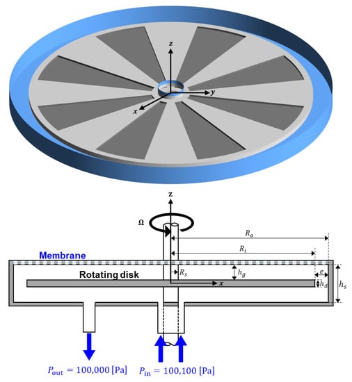
Figure 1.
The schematic representation of the dynamic filtration system consisting of a disk (in this figure, with eight engraved patterns) rotating with a constant angular velocity about the -axis, and a stationary housing. The feed is introduced through an annular-shaped inlet and exits the filtration system through an outlet. A constant pressure difference ( Pa) is applied between the inlet and outlet. A circular flat membrane with the radius is fixed on top of the housing.
The dynamic filtration system creates high shear stresses at the membrane surface, mainly induced by the mechanical movement of the disk rather than the feed flow rate. The pressure-driven flow due to may add hydrodynamic perturbations to the rotational flow, with the perturbations affected by the inlet flowrate that is slightly higher than the permeate flowrate [21,29,34]. Five disks are used to investigate the effect of the number of patterns on the flow and permeate flux at a specific operating condition. Figure 2 schematically depicts the patterns on the circular disk, where wheel-shaped surface patterns (areas filled with the black color) are engraved on both sides of the disk. The pattern depth is fixed to be 1.25 mm. In Figure 2, P00 stands for a plain disk (), P04 for a disk with , P08 for a disk with , etc.

Figure 2.
The five disks used in this study with the number of patterns 0, 4, 8, 12, and 16, which are denoted by P00, P04, P08, P12, and P16, respectively. In each patterned disk, engraved areas are filled with the black color. In the cases of patterned disks, the pattern depth is 1.25 mm.
For a given set of the geometrical parameters, fluid properties, and angular velocity of the disk, the rotating flow in a rotor-stator cavity is known to be governed by two dimensionless parameters [41], the aspect ratio and the Reynolds number Re, defined by
where and denote the density and the viscosity of the feed, respectively. The Reynolds number is defined using the characteristic velocity and the characteristics length . The feed fluid used in this study has the following density and viscosity: and . Thus, the two dimensionless parameters are and . When estimated from the diagram for the flow regimes in a rotor-stator cavity flow presented by Daily and Nece [41], the rotating flow caused by the plain disk (P00) belongs to the regime IV, which is characterized by turbulent flow, large clearance, and separate boundary layers. The diagram in [41] serves as the reference to categorize the flow in a rotor-stator-type dynamic filtration system in which the influence of the pressure-driven flow is not significant compared to the flow created by the rotating disk.
2.2. Modeling
If the criterion in [41] is applied to the values of Re and used in this study, the rotating flow is turbulent with separated boundary layers. The Reynolds-averaged Navier-Stokes (RANS) model [55] was used to describe the turbulent flow. In the case of incompressible Newtonian fluid flows, where the density and dynamic viscosity remain constant, the continuity and momentum equations for the mean velocity components (written in index notation in Cartesian coordinates) are given by
where is the time, the spatial coordinate in the -th direction, is the velocity component, is the pressure, and is the Reynolds stress tensor component. The velocity components and the pressure in Equations (3) and (4) are time-averaged quantities. In addition, the Shear Stress Transport (SST) turbulence model by Menter [56,57] is adopted to simulate the turbulent flow in the dynamic filtration system, as used in previous studies on rotating disk filtration systems [31,32]. The SST model is a two-equation model, which simultaneously solves two transport equations related to the turbulence kinetic energy and the specific dissipation rate . The fundamental idea of the turbulence model is to use the model in the boundary layer region, while activating the model outside the boundary layer, using a blending function. Then, the modification to the eddy viscosity is introduced.
When modeling flows due to rotating parts, in this study caused by a rotating patterned disk, the simulation methods using unsteady moving grids in the absolute reference frame are computationally expensive and cumbersome to use [58]. As an alternative to the moving grid methods, a multiple reference frame (MRF) method is a cost-effective way to analyze many engineering flows involving rotating parts, e.g., quadcopters, wind turbines, fans, mixing tanks, and turbine blades [59]. In this regard, an MRF method implemented in ANSYS CFX 18.1 (ANSYS Inc., Canonsburg, PA, USA) is used to solve the rotating flow in the dynamic filtration system. When using the MRF method, the computational domain is divided into two or more domains, which may be either rotating or stationary. When solving the governing equations for each domain, relevant data are exchanged at the interfaces between two different domains. After solving the governing equations, one can obtain the relative velocity in a moving reference frame, defined by
where is the relative velocity (the velocity viewed from a moving frame of reference), the absolute velocity (the velocity viewed from a stationary frame of reference), the angular velocity, and the position vector.
The boundary conditions for solving the governing equations are considered as follows. At the inlet (), a feed pressure of 100,100 Pa is imposed, and a pressure of 100,000 Pa is applied at the outlet (). Thus, the pressure difference between the inlet and outlet is kept at 100 Pa. On the membrane (), the permeate flux (the velocity normal to the membrane surface) is specified by
where is the outward unit normal vector, the membrane permeability constant (in this study ), and the transmembrane pressure (TMP). The details on the membrane used in numerical simulations will be introduced in Section 3.5 when dealing with the filtration performance in our dynamic filtration module. In this study, assuming that the gauge pressure on the permeate side is zero, the TMP is the pressure at the membrane surface. No-slip condition is specified at the disk surface () and at the shaft surface (). Thus, the circumferential velocity component on and (in the fixed coordinate) is , where the radial distance from the -axis. At the impermeable boundaries (), such as the housing walls, the no-slip and nonpenetration conditions are imposed, i.e., at .
2.3. Numerical Scheme
In this study, numerical simulations are conducted using commercial CFD software (ANSYS CFX 18.1), which is based on the finite volume method. The computational domains are discretized by hexahedral elements with the number of elements ranging from approximately 16,600,000 to 18,600,000 depending on the disk shape in the DF system. The number of elements is determined from a mesh convergence test, which will be introduced in Section 3.1. A high-resolution scheme is adopted to treat the convection terms in the governing equations, preventing numerical instabilities such as spurious oscillations or wiggles from occurring. As for solver, an algebraic multigrid (AMG) method is used in solving the governing equations in an iterative manner. All the computations have been conducted using parallel processing with 16 processors in a workstation with dual 16-core CPUs (Intel® Xeon® Gold 6130, 2.1 GHz) and 256 GB memory. The set of governing equations is solved using a convergence criterion with the RMS residuals less than .
3. Results and Discussion
This section begins with the results of a mesh convergence test that aimed to determine an optimal element size for the entirety of the simulations. Next, the flow characteristics induced by the rotating disk and the applied pressure difference between the inlet and outlet ports are introduced. In addition, the wall shear stress distribution on the membrane for each filtration system with a specific patterned disk is also evaluated. The shear stress-induced antifouling effect, closely related to the shear stress level at the membrane surface [51], is characterized by the area-averaged friction coefficient. Finally, the filtration performance is assessed using the permeate flux that is affected by both the disk shape and the disk rotating speed.
3.1. Mesh Convergence Test and Validation
First, the proper number of elements is determined through a mesh convergence test, guaranteeing a reliable solution with an affordable computational cost. For this purpose, numerical simulations for the filtration system with the plain disk (P00 in Figure 2) operating at rpm were conducted. The number of elements is varied from 4 to 20 million. In addition, the mesh is kept finer near the stator wall and the membrane surface to capture the large velocity gradients in the boundary layers. As for the convergence criterion, an RMS residual of is required to ensure the convergence of solutions. The average shear strain rate () at the membrane surface is employed as an indicator to check mesh convergence because it is sensitive to the velocity solution in the boundary layer. Figure 3 shows the change of the average wall shear strain rate as the number of elements () increases. The grid system with approximately 20 million elements, showing convergence with mesh refinement, is used in CFD simulations introduced in the following sections.
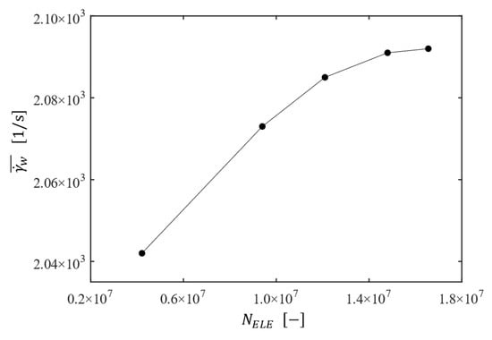
Figure 3.
The change of the average shear strain rate at the membrane wall as a function of the number of elements for the filtration system with the plain disk rotating at rpm.
To validate the numerical scheme used in this study, our velocity profile for an enclosed rotor-stator cavity flow with the aspect ratio 0.127 and the Reynolds number is compared with an experimental data reported by Cheah et al. [60]. The mesh for the cavity geometry used in the validation contains 2,880,000 hexahedral elements. Torras et al. [31] also compared their simulation results (obtained using commercial software Fluent 6.2) for the same geometry and operating condition with those in [60]. Figure 4 shows the time-averaged circumferential velocity () profiles at along the gap between the disk and the membrane surface for the three cases when . The red line is the velocity profile obtained from the present CFD simulation, while the circles and the black line are the velocity profiles from [60] and [31], respectively. Though the two CFD results show deviations from the experimental data near the stator surface (), they are in a good agreement with the experimentally measured velocity profile. As for predicting the velocity profile near the disk surface (), our CFD model predicts the experimental data better than that of [31], ensuring the accuracy of the present numerical scheme in predicting the flow characteristics of the rotor-stator cavity system.
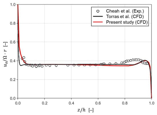
Figure 4.
Comparison of the mean circumferential velocity () profiles at along the gap between the disk and the membrane surface when . The red line indicates the velocity profile obtained numerically in the present study. Both circles and the black line are velocity profiles in [31] (reprinted from Torras et al. [31] with permission from Elsevier). The original experimental data (circles) are from Cheah et al. [60].
3.2. Flow Charactetistics
In the dynamic filtration (Figure 1), high wall shear stresses are created by the relative motion between the fixed membrane and a rotating patterned disk. Therefore, a better understanding of the in-depth flow characteristics is necessary to determine a proper set of design parameters and operating conditions resulting in an enhanced filtration performance and reduced membrane fouling. In what follows, all the velocity components are presented in terms of dimensionless variables. Here, the dimensionless radius (, the dimensionless mean velocity components ( and ), and the dimensionless axial coordinates are defined by , , and , where , and (see Figure 1 for the geometrical parameters).
First, the basic flow in the dynamic filtration system with a disk without pattern (the plain disk P00 in Figure 2) will be presented. Figure 5 depicts the dimensionless circumferential and radial velocity profiles ( and ) in the dimensionless axial direction at the four radial positions 0.25, 0.5, 0.75, and 1 (in this case located on the -axis), when rpm (corresponding to the Reynolds number of ). In Figure 5, the abscissa corresponds to the disk surface and to the membrane surface. The circumferential velocity profile (Figure 5a) clearly demonstrates the existence of three layers in the axial direction, a central core layer and two boundary layers separated by the core layer, which is a typical flow pattern in the regime IV of a rotor-stator cavity flow as defined by Daily and Nece [41]. This type of flow is called the Batchelor-type flow with three distinct zones: a centrifugal boundary layer close to the rotor (Ekman layer), a central core with negligible variation in , and a centripetal boundary layer near the stator (Bödewadt layer). Though it is not presented in the paper, the axial velocity magnitude is order of , and is thus quite small compared to the magnitude of the tangential and radial velocity components. The velocity gradients near the disk and membrane surfaces increase with , indicating that the frictional effect on both surfaces increases in the radial direction as well.
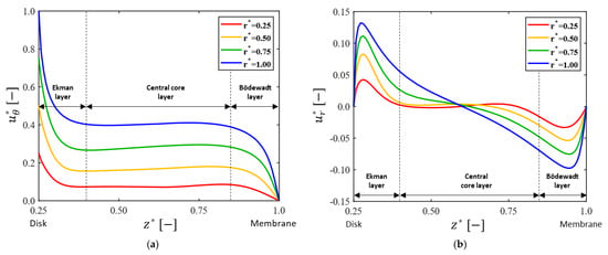
Figure 5.
The dimensionless circumferential and radial velocity profiles for the plain disk case (P00). Velocity profiles in the dimensionless axial direction are plotted at the four locations on the -axis with the dimensionless radial distance 0.25, 0.5, 0.75, and 1. Here, the angular velocity of the disks is rpm. The two velocity components are defined by and , where . (a) Dimensionless circumferential velocity ( ); (b) dimensionless radial velocity ( ). In the two plots, corresponds to the disk surface and to the membrane surface.
Next, the influence of the number of patterns on the velocity profiles was investigated, varying the number of patterns from 0 to 16 with an increment of 4 (Figure 2). By inserting wheel-shaped patterns on disk surfaces, complex vortices are expected to occur, affecting the mean velocity profiles, the radial distribution of pressure, the shear stress on the wall, and the permeate flux. The velocity profiles for and affected by the number of patterns are depicted in Figure 6, where the velocity components ( and in the axial direction) at 0.75 are plotted. When patterns are engraved on the disk, the circumferential velocity magnitude in the central core region increases. It was reported that increasing the magnitude of the circumferential velocity in the central core region produces a higher permeate flux at the same angular velocity [61]. Thus, one can expect a higher permeate flux as the number of patterns increases in the filtration module. The flux enhancement with will be discussed in Section 3.5.
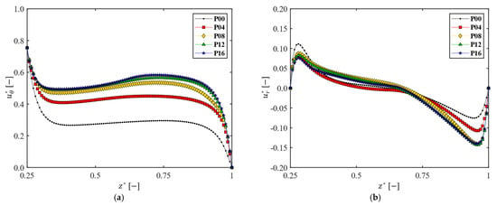
Figure 6.
The influence of the number of patterns on the dimensionless circumferential and radial velocity profiles. The velocity profiles are measured at a location on the -axis with the radial distance 0.75, when rpm. (a) Dimensionless circumferential velocity ( ); (b) dimensionless radial velocity (.
As the number of patterns increases, the magnitude of the velocity gradient decreases at the disk surface, but increases at the membrane surface (Figure 6a). The increase rate of the velocity gradient magnitude at the membrane surface () tends to be saturated when . In the case of a patterned disk, therefore, one can expect a higher shear stress on the membrane and better antifouling due to the higher wall shear stress, compared with those from a plain disk. The patterns on the rotating disk play a role in carrying the momentum caused by the disk rotation further into the central core region, leading to an increased velocity magnitude with in this region. As for the variation of with , there exist changes in the velocity profile near both walls. The magnitude of the velocity gradient at the membrane surface increases with , but it does not show any notable change as increases above 8, which is a similar trend to that observed in the change of . However, the influence of such changes on the frictional effect are not as significant as those observed in , since the magnitude of is one order of magnitude less than that of (Figure 6b). The quantitative analysis on the shear stress increase with the number of patterns will be discussed in Section 3.4.
Figure 7 shows the cross-sectional velocity vectors and contours for the value of the dimensionless axial velocity in the -plane. As depicted in Figure 7a, the flow pattern for the plain disk (P00) looks almost symmetric with respect to the midsurface (-plane) even though there are small perturbations due to the pressure-driven flow effect. The two counter-rotating cross-sectional flows near the rim of the housing generate a pair of Taylor vortices. Vortex structures varying with will be presented in Section 3.5. However, such symmetry is broken completely for the cases with patterns on the disk. As the number of patterns increases above 8, one cannot observe notable changes in the cross-sectional velocity vectors from a qualitative perspective.
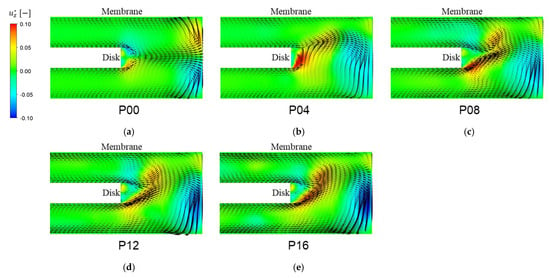
Figure 7.
The cross-sectional velocity vectors (in the -plane) influenced by the number of patterns when rpm. The color contour in each plot represents the value of the dimensionless axial velocity ( ) defined by . (a) (plain disk), (b) , (c) , (d) , and (e) .
3.3. Vortex Structure
The performance of a rotary dynamic filtration system is closely related to a secondary flow, such as Taylor vortices created by a high-speed rotation of a rotor, reducing membrane fouling or concentration polarization [18]. Such a secondary flow in membrane filtration also leads to enhanced mixing and improved fouling resistance via back transport of foulants from the membrane to the bulk flow region [27,53]. In addition, Taylor vortices are also associated with the enhanced shear rate in a dynamic filtration module [61]. In this regard, three-dimensional vortex structures due to the flow in the DF system are identified using the velocity field. Among several definitions representing the topology of a vortex core, the -definition of Jeong and Hussain [62] is adopted for vortex identification in our filtration system. In this definition, a vortex core is defined as a connected fluid region with two negative eigenvalues of . Here, and are the symmetric and antisymmetric parts of the velocity gradient tensor , respectively, where , and . If the three real eigenvalues ( and ) of the symmetric tensor are ordered as follows: , the definition is equivalent to the requirement that within the vortex core.
As far as vortex structures are concerned, our main concern is on the change of vortex structure with the number of patterns on the disk. As representative examples, vortex structures at a fixed rotation speed ( rpm) will be presented in this section. Figure 8 demonstrates the three-dimensional vortex structures using the -definition for the filtration modules with different number of patterns when the disk rotating speed is rpm. In this figure, vortex regions are identified by iso-surfaces of and color contours represent the magnitude of the dimensionless velocity . In the case of a plain disk (P00), a pair of Taylor vortices are observed in the radial gap between the disk and the outer housing (Figure 8a). The upper one represents rotating motions in the counter-clockwise direction and the lower one represents those in the clockwise direction, which are generated by the flow pattern depicted in Figure 7. In addition, vortices also emerge in the upper and lower axial gaps near the disk tip. Spiral vortices, skewed to the left (in the negative -direction), occur near the center of the filtration module. The skewness in the spiral vortices is due to the existence of the outlet port located at the bottom of the housing (see Figure 1). Thin vortices, which are stretched in the radial direction, are observed near the stator wall. In the cases of filtration modules with a patterned disk, there exists a significant difference in the vortex structures.
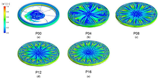
Figure 8.
The vortex structures affected by the number of patterns , visualized by -criterion when the angular velocity of the disk is . The color contour in each plot represents the dimensionless velocity magnitude ( ). (a) (plain disk), (b) , (c) , (d) , and (e) .
As the number of patterns increases, the two Taylor vortices become distorted, showing a wavy pattern (Figure 8b), and they are merged together at the highest (Figure 8e). The evolution of the vortex structures with , formed in the entire domain of the rotor-stator system, demonstrates the dependency of the vortex structures on the disk geometry. It should be noted again that, as the number of patterns increases above 8, the changes in the vortex structure in the radial gap between the disk and the housing begin to be saturated with .
3.4. Shear Stress Distribution
The flow and vortex structures presented in Section 3.2 and Section 3.3 revealed the number of patterns on the disk surface has a significant impact on the flow behavior in the dynamic filtration module. The rotational motions of the patterned disk can generate a high wall shear stress at the membrane surface as well, affected in this study by the number of patterns and the Reynolds number Re. In addition, the shear stress at the membrane is closely related to the control of membrane fouling and the filtration enhancement in dynamic filtration modules [25,26,27,30]. As such, we attempt to elucidate the variation of the wall shear stress at the membrane and its change with and Re.
The variation of the wall shear stress on the membrane was examined using the line-averaged friction coefficient at a radial position , defined by
where the integrand is evaluated along a circle on the membrane surface with the radius r and its center at . In Equation (7), is the dimensionless wall shear stress on the membrane, defined by
The numerator in Equation (8) is the local wall shear stress at the membrane surface, given by , where is the viscosity, the wall shear rate (), and the rate-of-deformation tensor (symmetric part of the velocity gradient tensor). The denominator in Equation (8) is the dynamic pressure defined with the characteristic velocity and the characteristics length . In the Cartesian coordinate system, the shear rate is evaluated using the following relation:
where , , and are velocity components in the –, –, and –directions, respectively.
Figure 9 shows the change of the line-averaged friction coefficient at the membrane surface as a function of the dimensionless radius for the five filtration modules with different numbers of patterns (, 4, 8, 12, and 16). Though the rotation speed is a factor with an influence on the shear stresses [63], the friction coefficient when rpm (equivalent to ) is presented as a representative example. In the case of the plain disk with (P00), the friction coefficient increases with , reaches a peak value around , and decreases rapidly near the stator side wall. Such variation of with can also be inferred from Figure 5 showing the velocity components ( and ) and their changes in the -direction. If wheel-shaped patterns are engraved on the disk surfaces, a different profile of is observed in each filtration module. In cases of disks with patterns, the overall values of increased significantly as increased, compared to the case with (P00). When (P16 in Figure 9), the maximum friction coefficient is approximately two times higher than that of the case with , and the peak value is observed around .
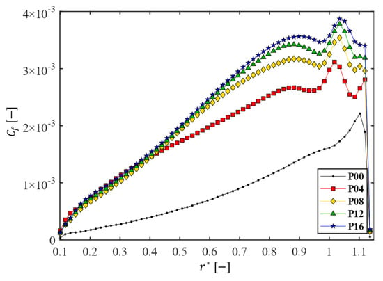
Figure 9.
The change of the line-averaged friction coefficient at the membrane surface as a function of the dimensionless radius for the five filtration modules with different numbers of patterns on the disk. Here, rpm.
The influence of the number of patterns () and the Reynolds number (Re) on the wall shear stress is investigated by utilizing a friction coefficient. To evaluate the influence of and Re on the skin friction over the entire membrane surface, the area-averaged friction coefficient is defined as follows:
where denotes the membrane area ( m2) and the domain on the membrane. Figure 10 shows the change of the area-averaged friction coefficient () influenced by and Re. Here, the disk rotating speed is varied from 200 to 1000 rpm (thus, Re is varied from to ). Figure 10a plots as a function of at the five Reynolds numbers, while Figure 10b plots as a function of Re at the five values of . As increases increases as well, but the increase rate of shows a noticeable slowdown when , regardless of the Reynolds number (Figure 10a). As for the effect of Re on the skin friction, decreases with Re and the decrease rate of increases as increases (Figure 10b). Although decreases with Re, the magnitude of itself increases with Re. In summary, the filtration dynamic module with a patterned disk leads to a higher friction coefficient than that of the plain disk and the increase rate of with slows down as the number of patterns increases above 8.
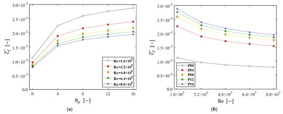
Figure 10.
The change of the area-averaged friction coefficient (). (a) as a function of the numbers of patterns at the five Reynolds numbers; (b) as a function of the Reynolds number, affected by .
3.5. Filtration Performance
Filtration enhancement due to the patterned disk in the dynamic filtration module is demonstrated for a microfiltration process. In a microfiltration membrane, the permeate flux through the membrane is given by . Assuming that the membrane pores are well-connected, uniform, and cylindrical in shape, the permeability constant [64] is evaluated using the following relation:
where is the porosity, the pore radius, the tortuosity, and the membrane thickness. Using the following parameters for the membrane and the feed fluid, , , Pa∙s, , and , the permeability constant is m/s·Pa. Though membrane fouling is a major problem in most membrane processes, the fixed value of is assumed, limiting our interest to the flux enhancement due to the rotating patterned disk in the dynamic filtration system with an uncontaminated membrane. As mentioned in Section 2.2, the local pressure at a specific location on the membrane is used as , assuming that the gauge pressure in the permeate side is zero.
The flux enhancement due to a patterned disk is characterized by a dimensionless permeate flux ,
where is the reference flux, defined by . Using Pa (reference TMP), the reference flux is LMH (L/m2·h), which is equivalent to m/s. The change of in the radial direction is assessed using a line-averaged dimensionless permeate flux , given by
which is defined in an analogous manner to the definition of (Equation (7)). To evaluate overall filtration performance of the filtration system influenced by and Re, the area-averaged dimensionless permeate flux is defined as follows:
Figure 11 shows the line-averaged dimensionless permeate flux as a function of the dimensionless radial coordinate for the five filtration modules with a different number of patterns. In all cases, increases with because the pressure at the membrane (TMP) increases in the radial direction. When a patterned disk is used, near the center is lower, compared with that of the module with the plain disk, but becomes higher in the outer portion of the membrane, bringing benefit in the permeate flux. As the number of patterns increases, the increase of is significant up to the number of patterns , and it tends to be saturated when . When rpm (), the highest flux obtained with is (equivalent to 182 LMH), which is not a significant gain in the permeate flux. When rpm (), however, the highest flux obtained with is , now equivalent to 225 LMH. The variation of in the radial direction confirms that the effectiveness of the DF module is closely related to both the rotating speed of the patterned disk and the number of patterns.
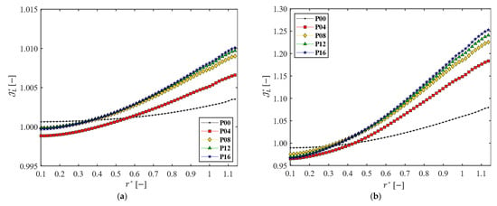
Figure 11.
The line-averaged dimensionless permeate flux as functions of the dimensionless radius ( ) for the five disks, when (a) rpm ( ) and (b) rpm ( ).
Finally, the overall flux enhancement with the patterned disk was assessed using the area-averaged permeate flux (), depicted in Figure 12. Within the range of and used in this study, the maximum area-averaged permeate flux (obtained with and ) is approximately 1.13 (equivalent to 203 LMH). The proper number of patterns seems to be eight, since one cannot achieve a notable gain in when . As for the effect of Re on , the higher the Reynolds number, the larger the gain in the permeate flux caused by the use of a patterned disk.
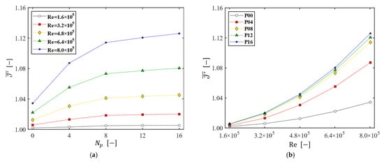
Figure 12.
The area-averaged permeate flux (). (a) as a function of at the five Reynolds numbers; (b) as a function of Re for the five disks.
4. Conclusions
In this study, the effect of disk geometry on the permeate flux enhancement in a dynamic filtration (DF) system is numerically investigated. The DF system consists of a disk (rotor) and a stator with a membrane fixed on top of the stator. Wheel-shaped patterns are engraved on both sides of a disk with a number of patterns () on one side varying from 0 to 16. The aspect ratio , the axial clearance (between the disk and the membrane) divided by the disk radius, is fixed at 0.0511. A constant pressure difference of 100 Pa is maintained between the inlet and outlet. The Reynolds number (Re) is varied from to by changing the disk rotating speed () from 200 to 1000 rpm. The SST turbulence model is employed to solve the turbulent rotating flows and the MRF method is adopted to treat the rotating disk in quasi-steady state.
The flow characteristics in the DF system are examined to understand the detailed flow affected by and Re. The velocity profiles along the axial direction revealed the Batchelor-type flow with two boundary layers (near the disk and membrane surfaces) and a central core layer in all Reynolds numbers. For a constant angular velocity, as the number of patterns increases, the magnitude of the circumferential velocity in the central core layer increases, which not only increases the shear stress applied to the membrane surface but also improves the permeate flux. The vortex structure in the dynamic filtration system is visualized via the -criterion, demonstrating complex vortex structures generated by the perturbation due to the patterned surfaces. The changes of flow characteristics (velocity profiles, shear stresses, and vortex structures) and the overall permeate flux tend to be saturated as increases above 8, implying that is a proper choice for the number of patterns in the DF system. Within the range of and investigated in this study, the maximum area-averaged permeate flux obtained when and is approximately 203 LMH, while the flux for the plain disk at the same Re is approximately 185 LMH. It should be noted that a rotating disk with a proper number of patterns resulted in a higher wall shear stress, mitigating membrane fouling and a higher permeate flux compared to that from a filtration system with a plain disk, but the gain in the permeate flux is highly affected by the Reynolds number (or the disk rotating speed ). The higher the Reynolds number, the larger the gain in the permeate flux from a patterned disk in the DF system.
As a fundamental study on the hydrodynamics in a rotor-stator-type DF system, this study presents new insights into the effect of the pattered disk on the flow and filtration performance in the DF system that have not been previously explored. In future work, we plan to investigate the concentration distribution and permeate flux enhancement in a reverse-osmosis DF system with patterned disks, and to solve the associated flow and mass transfer problems.
Author Contributions
Conceptualization, T.G.K. and J.E.P.; formal analysis, J.E.P.; investigation, T.G.K. and J.E.P.; resources, T.G.K. and H.M.; writing—original draft preparation, J.E.P.; writing—review and editing, T.G.K. and H.M.; visualization, J.E.P.; supervision, T.G.K. and H.M.; project administration, T.G.K. and H.M.; funding acquisition, T.G.K. and H.M. All authors have read and agreed to the published version of the manuscript.
Funding
This research was supported by the 2019 Korea Aerospace University Faculty Research grant and a National Research Foundation (NRF) grant funded by the Korean government (MSIT) (grant number: 2022R1A2C1007886).
Institutional Review Board Statement
Not applicable.
Data Availability Statement
The data supporting the findings of this study are available from the corresponding author upon reasonable request.
Conflicts of Interest
The authors declare no conflict of interest.
Abbreviations
| AMG | Algebraic multigrid |
| CFD | Computational fluid dynamics |
| CFF | Crossflow filtration |
| CP | Concentration polarization |
| DF | Aynamic filtration |
| MRF | Multiple reference frame |
| MSD | Multishift disk |
| RANS | Reynolds-averaged Navier-Stokes |
| RMS | Root mean square |
| SST | Shear stress transport |
| SWM | spiral-wound module |
| TMP | transmembrane pressure |
| List of Symbols | |
| Membrane area, m2 | |
| Pore radius of membrane, μm | |
| Friction coefficient | |
| Area-averaged friction coefficient | |
| Symmetric part of velocity gradient, 1/s | |
| Aspect ratio | |
| Gap from the x–axis to membrane, mm | |
| Axial gap, mm | |
| Permeate flux, m/s | |
| Reference permeate flux, m/s | |
| Dimensionless permeate flux | |
| Area-averaged dimensionless permeate flux | |
| Membrane permeability, m/s·Pa | |
| Turbulence kinetic energy, J/kg | |
| Membrane thickness, μm | |
| Number of elements | |
| Number of patterns on one side of a disk | |
| Outward unit normal vector | |
| Pressure, Pa | |
| Pressure at the inlet, Pa | |
| Pressure at the outlet, Pa | |
| Radius, mm | |
| Disk radius, mm | |
| Stator radius, mm | |
| Shaft radius, mm | |
| Re | Reynolds number |
| Radial distance from the z–axis, mm | |
| Dimensionless radius | |
| Time, s | |
| Reynolds stress tensor, Pa | |
| Linear velocity, m/s | |
| Velocity vector, m/s | |
| Relative velocity vector, m/s | |
| Circumferential velocity, m/s | |
| Radial velocity, m/s | |
| Axial velocity, m/s | |
| Dimensionless velocity vector | |
| Dimensionless circumferential velocity | |
| Dimensionless radial velocity | |
| Dimensionless axial velocity | |
| Antisymmetric part of velocity gradient, 1/s | |
| Dimensionless z–coordinate | |
| Greek Letters | |
| Inlet boundary | |
| Outlet boundary | |
| Membrane (permeable boundary) | |
| Disk surface | |
| Shaft surface | |
| Impermeable boundary | |
| Shear rate, 1/s | |
| Wall shear rate, 1/s | |
| Average wall shear rate, 1/s | |
| Difference | |
| Tortuosity | |
| Real eigenvalue | |
| Viscosity of fluid, Pa·s | |
| Density of fluid, kg/m3 | |
| Wall shear stress, Pa | |
| Dimensionless wall shear stress | |
| Porosity | |
| Angular velocity, 1/s | |
| Specific dissipation rate, 1/s |
References
- Cui, Z.; Jiang, Y.; Field, R. Fundamentals of Pressure-Driven Membrane Separation Processes. In Membrane Technology, 1st ed.; Cui, Z., Muralidhara, H., Eds.; Butterworth-Heinemann: Oxford, UK, 2010; Volume 1, pp. 1–18. [Google Scholar] [CrossRef]
- Sablani, S.; Goosen, M.; Al-Belushi, R.; Wilf, M. Concentration polarization in ultrafiltration and reverse osmosis: A critical review. Desalination 2001, 141, 269–289. [Google Scholar] [CrossRef]
- Zydney, A.L. Stagnant film model for concentration polarization in membrane systems. J. Membr. Sci. 1997, 130, 275–281. [Google Scholar] [CrossRef]
- Mariñas, B.J.; Urama, R.I. Modeling concentration-polarization in reverse osmosis spiral-wound elements. J. Environ. Eng. 1996, 122, 292–298. [Google Scholar] [CrossRef]
- Hoek, E.M.; Elimelech, M. Cake-enhanced concentration polarization: A new fouling mechanism for salt-rejecting membranes. Environ. Sci. Technol. 2003, 37, 5581–5588. [Google Scholar] [CrossRef] [PubMed]
- Porter, M.C. Concentration polarization with membrane ultrafiltration. Ind. Eng. Chem. Prod. Res. Dev. 1972, 11, 234–248. [Google Scholar] [CrossRef]
- She, Q.; Wang, R.; Fane, A.G.; Tang, C.Y. Membrane fouling in osmotically driven membrane processes: A review. J. Membr. Sci. 2016, 499, 201–233. [Google Scholar] [CrossRef]
- Tummons, E.; Han, Q.; Tanudjaja, H.J.; Hejase, C.A.; Chew, J.W.; Tarabara, V.V. Membrane fouling by emulsified oil: A review. Sep. Purif. Technol. 2020, 248, 116919. [Google Scholar] [CrossRef]
- AlSawaftah, N.; Abuwatfa, W.; Darwish, N.; Husseini, G.A. A Review on Membrane Biofouling: Prediction, Characterization, and Mitigation. Membranes 2022, 12, 1271. [Google Scholar] [CrossRef] [PubMed]
- Jung, S.Y.; Jung, H.I.; Kang, T.G.; Ahn, K.H. Fouling Mitigation in Crossflow Filtration Using Chaotic Advection: A Numerical Study. AIChE J. 2020, 66, e16792. [Google Scholar] [CrossRef]
- Baitalow, K.; Wypysek, D.; Leuthold, M.; Weisshaar, S.; Lölsberg, J.; Wessling, M. A Mini-Module with Built-in Spacers for High-Throughput Ultrafiltration. J. Memb. Sci. 2021, 637, 119602. [Google Scholar] [CrossRef]
- Chevarin, C.; Wang, X.; Bouyer, D.; Tarabara, V.; Chartier, T.; Ayral, A. CFD-guided patterning of tubular ceramic membrane surface by stereolithography: Optimizing morphology at the mesoscale for improved hydrodynamic control of membrane fouling. J. Membr. Sci. 2023, 672, 121435. [Google Scholar] [CrossRef]
- Lin, W.; Wang, Q.; Sun, L.; Wang, D.; Cabrera, J.; Li, D.; Hu, L.; Jiang, G.; Wang, X.M.; Huang, X. The Critical Role of Feed Spacer Channel Porosity in Membrane Biofouling: Insights and Implications. J. Memb. Sci. 2022, 649, 120395. [Google Scholar] [CrossRef]
- Lin, W.; Lei, J.; Wang, Q.; Wang, X.M.; Huang, X. Performance Enhancement of Spiral-Wound Reverse Osmosis Membrane Elements with Novel Diagonal-Flow Feed Channels. Desalination 2022, 523, 115447. [Google Scholar] [CrossRef]
- Lin, W.; Li, D.; Wang, Q.; Wang, X.M.; Huang, X. Dynamic Evolution of Membrane Biofouling in Feed Channels Affected by Spacer–Membrane Clearance and the Induced Hydrodynamic Conditions. J. Memb. Sci. 2023, 668, 121209. [Google Scholar] [CrossRef]
- Guan, H.; Lin, P.; Yu, S.; Hu, X.; Li, X.; Zhu, Z. Hydrodynamic effects of nonuniform feed spacer structures on energy loss and mass transfer in spiral wound module. J. Membr. Sci. 2023, 673, 121479. [Google Scholar] [CrossRef]
- Kroner, K.H.; Nissinen, V. Dynamic filtration of microbial suspensions using an axially rotating filter. J. Membr. Sci. 1988, 36, 85–100. [Google Scholar] [CrossRef]
- Holeschovsky, U.B.; Cooney, C.L. Quantitative description of ultrafiltration in a rotating filtration device. AIChE J. 1991, 37, 1219–1226. [Google Scholar] [CrossRef]
- Lee, S.S.; Burt, A.; Russotti, G.; Buckland, B. Microfiltration of recombinant yeast cells using a rotating disk dynamic filtration system. Biotechnol. Bioeng. 1995, 48, 386–400. [Google Scholar] [CrossRef] [PubMed]
- Ding, L.H.; Jaffrin, M.Y.; Mellal, M.; He, G. Investigation of performances of a multishaft disk (MSD) system with overlapping ceramic membranes in microfiltration of mineral suspensions. J. Membr. Sci. 2006, 276, 232–240. [Google Scholar] [CrossRef]
- He, G.; Ding, L.H.; Paullier, P.; Jaffrin, M.Y. Experimental study of a dynamic filtration system with overlapping ceramic membranes and non-permeating disks rotating at independent speeds. J. Membr. Sci. 2007, 300, 63–70. [Google Scholar] [CrossRef]
- Uppu, A.; Chaudhuri, A.; Das, S.P. Numerical modeling of particulate fouling and cake-enhanced concentration polarization in roto-dynamic reverse osmosis filtration systems. Desalination 2019, 468, 114053. [Google Scholar] [CrossRef]
- Uppu, A.; Chaudhuri, A.; Das, S.P.; Prakash, N. CFD modeling of gypsum scaling in cross-flow RO filters using moments of particle population balance. J. Environ. Chem. Eng. 2020, 8, 104151. [Google Scholar] [CrossRef]
- Prakash, N.; Chaudhuri, A.; Das, S.P. Numerical modelling and analysis of concentration polarization and scaling of gypsum over RO membrane during seawater desalination. Chem. Eng. Res. Des. 2023, 190, 497–507. [Google Scholar] [CrossRef]
- Jaffrin, M.Y. Dynamic shear-enhanced membrane filtration: A review of rotating disks, rotating membranes and vibrating systems. J. Membr. Sci. 2008, 324, 7–25. [Google Scholar] [CrossRef]
- Jaffrin, M.Y. Hydrodynamic techniques to enhance membrane filtration. Annu. Rev. Fluid Mech. 2012, 44, 77–96. [Google Scholar] [CrossRef]
- Cheng, M.; Xie, X.; Schmitz, P.; Fillaudeau, L. Extensive review about industrial and laboratory dynamic filtration modules: Scientific production, configurations and performances. Sep. Purif. Technol. 2021, 265, 118293. [Google Scholar] [CrossRef]
- Kim, K.; Jung, J.-Y.; Kwon, J.-H.; Yang, J.-W. Dynamic microfiltration with a perforated disk for effective harvesting of microalgae of microalgae. J. Membr. Sci. 2015, 475, 252–258. [Google Scholar] [CrossRef]
- Jogdand, A.; Chaudhuri, A. Modeling of concentration polarization and permeate flux variation in a roto-dynamic reverse osmosis filtration system. Desalination 2015, 375, 54–70. [Google Scholar] [CrossRef]
- Xie, X.; Le Men, C.; Dietrich, N.; Schmitz, P.; Fillaudeau, L. Local hydrodynamic investigation by PIV and CFD within a Dynamic filtration unit under laminar flow. Sep. Purif. Technol. 2018, 198, 38–51. [Google Scholar] [CrossRef]
- Torras, C.; Pallares, J.; Garcia-Valls, R.; Jaffrin, M.Y. Numerical simulation of the flow in a rotating disk filtration module. Desalination 2009, 235, 122–138. [Google Scholar] [CrossRef]
- Pinilla, A.; Berrio, J.C.; Guerrero, E.; Valdés, J.P.; Becerra, D.; Pico, P.; Vargas, L.; Madsen, S.; Bentzen, T.R.; Ratkovich, N. CFD modelling of the hydrodynamics in a filtration unit with rotating membranes. J. Water Proc. Eng. 2020, 36, 101368. [Google Scholar] [CrossRef]
- Childs, P.R. Rotating Flow, 1st ed.; Butterworth-Heinemann: Oxford, UK, 2010; pp. 1–15. [Google Scholar] [CrossRef]
- Launder, B.; Poncet, S.; Serre, E. Laminar, transitional, and turbulent flows in rotor-stator cavities. Annu. Rev. Fluid Mech. 2010, 42, 229–248. [Google Scholar] [CrossRef]
- Ekman, V.W. On the influence of the earth’s rotation on ocean-currents. Ark. Mat. Astr. Fys. 1905, 2, 1–52. [Google Scholar]
- Kármán, T.V. Über laminare und turbulente Reibung. J. Appl. Math. Mech. 1921, 1, 233–252. [Google Scholar] [CrossRef]
- Bödewadt, V.U. Die drehströmung über festem grunde. J. Appl. Math. Mech. 1940, 20, 241–253. [Google Scholar] [CrossRef]
- Batchelor, G.K. Note on a class of solutions of the Navier-Stokes equations representing steady rotationally-symmetric flow. Q. J. Mech. Appl. Math. 1951, 4, 29–41. [Google Scholar] [CrossRef]
- Stewartson, K. On the flow between two rotating coaxial disks. Math. Proc. Camb. Philos. Soc. 1953, 49, 333–341. [Google Scholar] [CrossRef]
- Zandbergen, P.J.; Dijkstra, D. Von Kármán swirling flows. Annu. Rev. Fluid Mech. 1987, 19, 465–491. [Google Scholar] [CrossRef]
- Daily, J.W.; Nece, R.E. Chamber dimension effects on induced flow and frictional resistance of enclosed rotating disks. J. Fluids Eng. 1960, 82, 217–230. [Google Scholar] [CrossRef]
- Chew, J.W.; Owen, J.M.; Pincombe, J.R. Numerical predictions for laminar source-sink flow in a rotating cylindrical cavity. J. Fluid Mech. 1984, 143, 451–466. [Google Scholar] [CrossRef]
- Chew, J.W. Development of a computer program for the prediction of flow in a rotating cavity. Int. J. Numer. Methods Fluids 1984, 4, 667–683. [Google Scholar] [CrossRef]
- Stroock, A.D.; Dertinger, S.K.W.; Ajdari, A.; Mezić, I.; Stone, H.A.; Whitesides, G.M. Chaotic mixer for microchannels. Science 2002, 295, 647–651. [Google Scholar] [CrossRef] [PubMed]
- Kang, T.G.; Singh, M.K.; Kwon, T.H.; Anderson, P.D. Chaotic mixing using periodic and aperiodic sequences of mixing protocols in a micromixer. Microfluid. Nanofluidics 2008, 4, 589–599. [Google Scholar] [CrossRef]
- Jang, H.K.; Kim, Y.J.; Woo, N.S.; Hwang, W.R. Tensorial Navier-slip boundary conditions for patterned surfaces for fluid mixing: Numerical simulations and experiments. AIChE J. 2016, 62, 4574–4585. [Google Scholar] [CrossRef]
- Jung, H.I.; Park, J.E.; Jung, S.Y.; Kang, T.G.; Ahn, K.H. Flow and mixing characteristics of a groove-embedded partitioned pipe mixer. Korea-Aust. Rheol. J. 2020, 32, 319–329. [Google Scholar] [CrossRef]
- Jung, S.Y.; Won, Y.-J.; Jang, J.H.; Yoo, J.H.; Ahn, K.H.; Lee, C.-H. Particle deposition on the patterned membrane surface: Simulation and experiments. Desalination 2015, 370, 17–24. [Google Scholar] [CrossRef]
- Jung, S.Y.; Ahn, K.H. Transport and deposition of colloidal particles on a patterned membrane surface: Effect of cross-flow velocity and the size ratio of particle to surface pattern. J. Membr. Sci. 2019, 572, 309–319. [Google Scholar] [CrossRef]
- Zhou, Z.; Ling, B.; Battiato, I.; Husson, S.M.; Ladner, D.A. Concentration polarization over reverse osmosis membranes with engineered surface features. J. Membr. Sci. 2021, 617, 118199. [Google Scholar] [CrossRef]
- Choi, W.; Lee, C.; Yoo, C.H.; Shin, M.G.; Lee, G.W.; Kim, T.-S.; Jung, H.W.; Lee, J.S.; Lee, J.-H. Structural tailoring of sharkskin-mimetic patterned reverse osmosis membranes for optimizing biofouling resistance. J. Membr. Sci. 2020, 595, 117602. [Google Scholar] [CrossRef]
- Malakian, A.; Zhou, Z.; Messick, L.; Spitzer, T.N.; Ladner, D.A.; Husson, S.M. Understanding the role of pattern geometry on nanofiltration threshold flux. Membranes 2020, 10, 445. [Google Scholar] [CrossRef]
- Kim, K.T.; Park, J.E.; Jung, S.Y.; Kang, T.G. Fouling Mitigation via Chaotic Advection in a Flat Membrane Module with a Patterned Surface. Membranes 2021, 11, 724. [Google Scholar] [CrossRef]
- Jung, S.Y.; Park, J.E.; Kang, T.G.; Ahn, K.H. Design optimization for a microfluidic crossflow filtration system incorporating a micromixer. Micromachines 2019, 10, 836. [Google Scholar] [CrossRef]
- Argyropoulos, C.D.; Markatos, N.C. Recent advances on the numerical modelling of turbulent flows. Appl. Math. Model. 2015, 39, 693–732. [Google Scholar] [CrossRef]
- Menter, F.R. Two-equation eddy-viscosity turbulence models for engineering applications. AIAA J. 1994, 32, 1598–1605. [Google Scholar] [CrossRef]
- Menter, F.R. Review of the shear-stress transport turbulence model experience from an industrial perspective. Int. J. Comput. Fluid Dyn. 2009, 23, 305–316. [Google Scholar] [CrossRef]
- Zadravec, M.; Basic, S.; Hribersek, M. The influence of rotating domain size in a rotating frame of reference approach for simulation of rotating impeller in a mixing vessel. J. Eng. Sci. Technol. 2007, 2, 126–138. [Google Scholar]
- Silva, P.A.S.F.; Tsoutsanis, P.; Antoniadis, A.F. Simple multiple reference frame for high-order solution of hovering rotors with and without ground effect. Aerosp. Sci. Technol. 2021, 111, 106518. [Google Scholar] [CrossRef]
- Cheah, S.C.; Iacovides, H.; Jackson, D.C.; Ji, H.; Launder, B.E. Experimental investigation of enclosed rotor-stator disk flows. Exp. Therm. Fluid Sci. 1994, 9, 445–455. [Google Scholar] [CrossRef]
- Bouzerar, R.; Jaffrin, M.Y.; Ding, L.; Paullier, P. Influence of geometry and angular velocity on performance of a rotating disk filter. AIChE J. 2000, 46, 257–265. [Google Scholar] [CrossRef]
- Jeong, J.; Hussain, F. On the identification of a vortex. J. Fluid Mech. 1995, 285, 69–94. [Google Scholar] [CrossRef]
- Takata, K.; Tanida, K. Effect of UF Membrane Rotation on Filtration Performance Using High Concentration Latex Emulsion Solution. Membranes 2022, 12, 422. [Google Scholar] [CrossRef] [PubMed]
- Purkait, M.; Singh, R. Membrane Technology in Separation Science, 1st ed.; CRC Press: Boca Raton, FL, USA, 2017; pp. 53–54. [Google Scholar] [CrossRef]
Disclaimer/Publisher’s Note: The statements, opinions and data contained in all publications are solely those of the individual author(s) and contributor(s) and not of MDPI and/or the editor(s). MDPI and/or the editor(s) disclaim responsibility for any injury to people or property resulting from any ideas, methods, instructions or products referred to in the content. |
© 2023 by the authors. Licensee MDPI, Basel, Switzerland. This article is an open access article distributed under the terms and conditions of the Creative Commons Attribution (CC BY) license (https://creativecommons.org/licenses/by/4.0/).