
Hydrogen-Tolerant La0.6Ca0.4Co0.2Fe0.8O3–d Oxygen Transport Membranes from Ultrasonic Spray Synthesis for Plasma-Assisted CO2 Conversion

 , , ,
, , , 
 ,
, 

Abstract
1. Introduction
2. Materials and Methods
2.1. Membrane Synthesis
2.2. Material Characterisation
2.3. Oxygen Permeation Measurements
3. Results
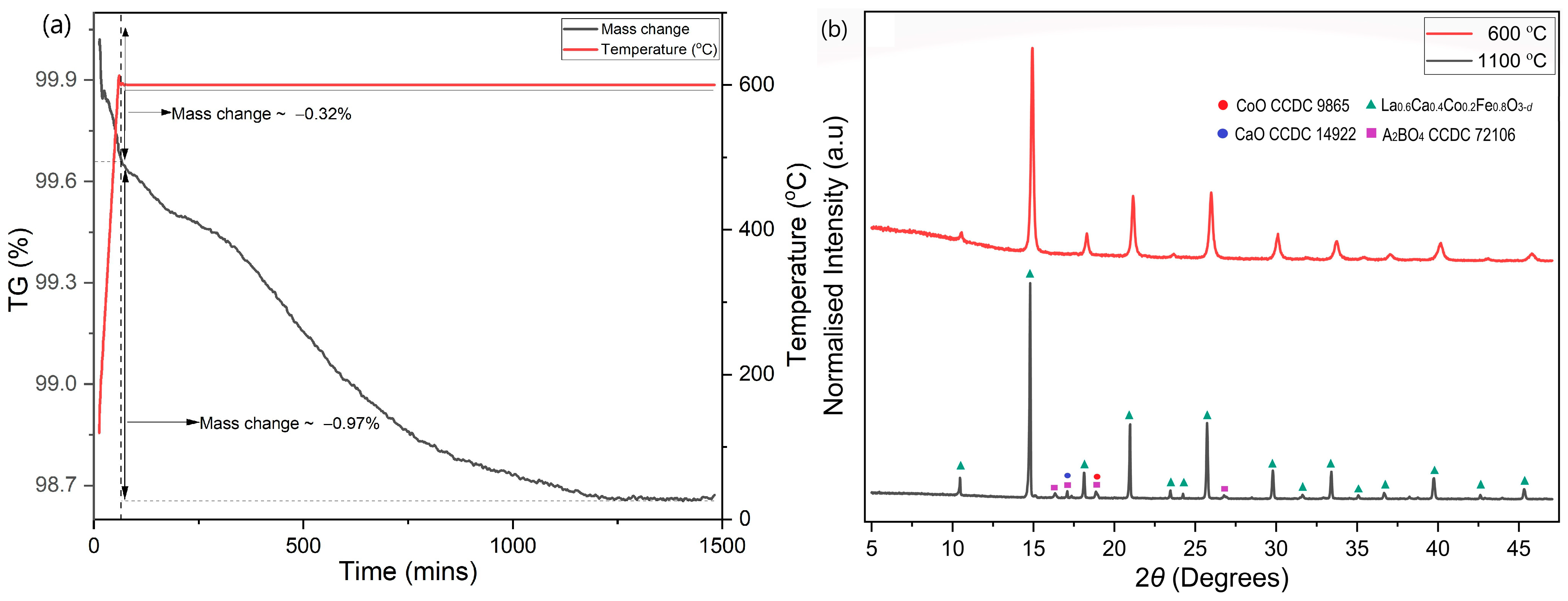
3.1. XRD
3.2. SEM
3.3. Chemical Analysis
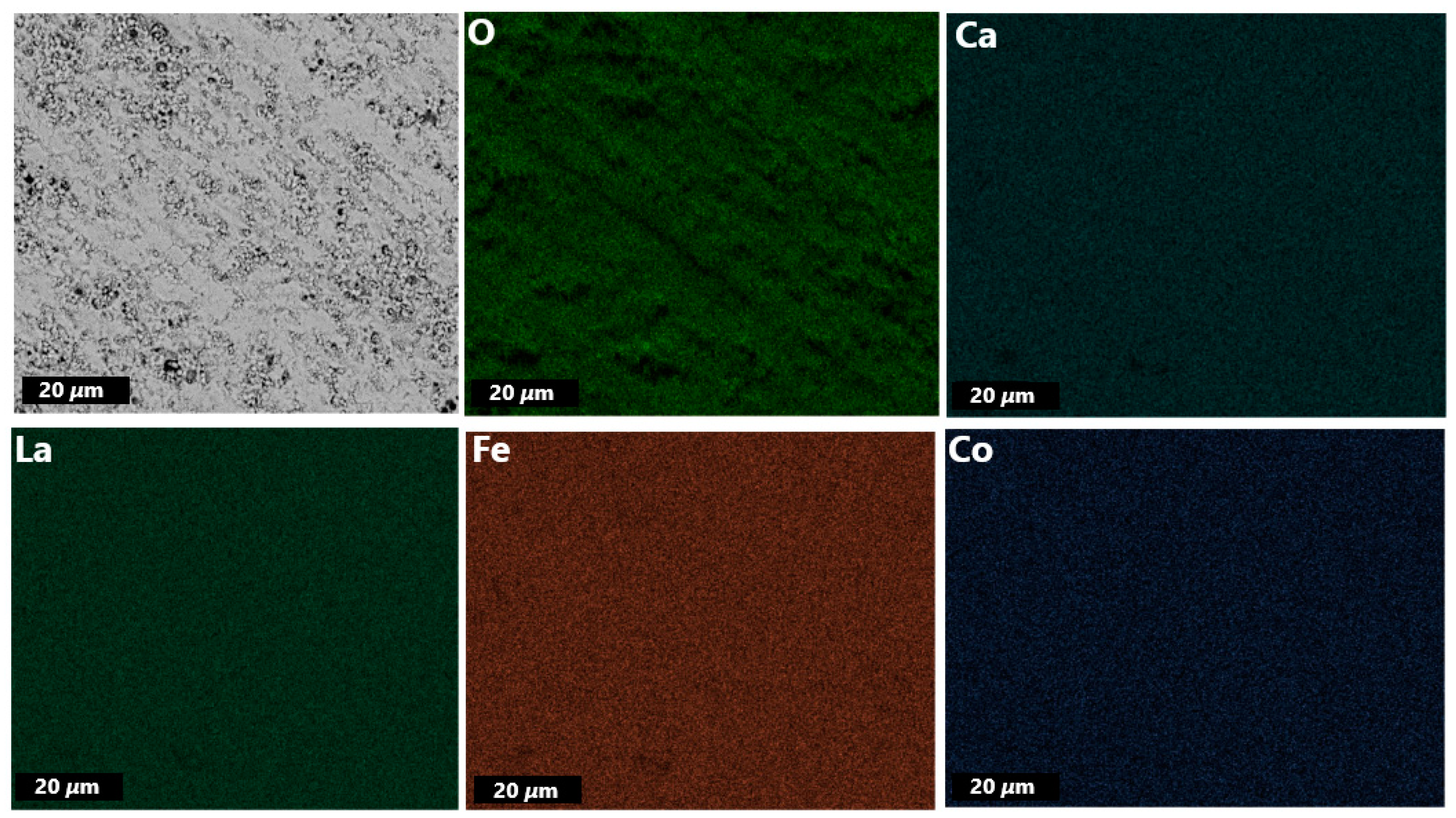
3.3.1. EDXS
3.3.2. ICP-OES
3.3.3. Hot Gas Extraction Analysis
3.4. Thermal Analysis
3.5. Preliminary Plasma Test
3.6. Oxygen Permeation Performance
4. Discussion
5. Conclusions
Supplementary Materials
Author Contributions
Funding
Data Availability Statement
Acknowledgments
Conflicts of Interest
References
- Worrell, E.; Allwood, J.; Gutowski, T. The role of material efficiency in environmental stewardship. Annu. Rev. Environ. Resour. 2016, 41, 575–598. [Google Scholar] [CrossRef]
- Miller, S.A.; Horvath, A.; Monteiro, P.J. Readily implementable techniques can cut annual CO2 emissions from the production of concrete by over 20%. Environ. Res. Lett. 2016, 11, 074029. [Google Scholar] [CrossRef]
- Gibbins, J.; Chalmers, H. Carbon capture and storage. Energy Policy 2008, 36, 4317–4322. [Google Scholar] [CrossRef]
- Madejski, P.; Chmiel, K.; Subramanian, N.; Kuś, T. Methods and techniques for CO2 capture: Review of potential solutions and applications in modern energy technologies. Energies 2022, 15, 887. [Google Scholar] [CrossRef]
- Anwar, M.N.; Fayyaz, A.; Sohail, N.F.; Khokhar, M.F.; Baqar, M.; Khan, W.D.; Rasool, K.; Rehan, M.; Nizami, A.S. CO2 capture and storage: A way forward for sustainable environment. J. Environ. Manag. 2018, 226, 131–144. [Google Scholar] [CrossRef] [PubMed]
- Chen, G.; Buck, F.; Kistner, I.; Widenmeyer, M.; Schiestel, T.; Schulz, A.; Walker, M.; Weidenkaff, A. A novel plasma-assisted hollow fiber membrane concept for efficiently separating oxygen from CO in a CO2 plasma. Chem. Eng. J. 2020, 392, 123699. [Google Scholar] [CrossRef]
- Bogaerts, A.; Neyts, E.C. Plasma technology: An emerging technology for energy storage. ACS Energy Lett. 2018, 3, 1013–1027. [Google Scholar] [CrossRef]
- Snoeckx, R.; Bogaerts, A. Plasma technology—A novel solution for CO2 conversion? Chem. Soc. Rev. 2017, 46, 5805–5863. [Google Scholar] [CrossRef]
- Currie, R.; Fowler, M.W.; Simakov, D.S. Catalytic membrane reactor for CO2 hydrogenation using renewable streams: Model-based feasibility analysis. Chem. Eng. J. 2019, 372, 1240–1252. [Google Scholar] [CrossRef]
- Jin, W.; Zhang, C.; Chang, X.; Fan, Y.; Xing, W.; Xu, N. Efficient catalytic decomposition of CO2 to CO and O2 over Pd/mixed-conducting oxide catalyst in an oxygen-permeable membrane reactor. Environ. Sci. Technol. 2008, 42, 3064–3068. [Google Scholar] [CrossRef]
- Wu, X.Y.; Ghoniem, A.F. Mixed ionic-electronic conducting (MIEC) membranes for thermochemical reduction of CO2: A review. Prog. Energy Combust. Sci. 2019, 74, 1–30. [Google Scholar] [CrossRef]
- Zhang, K.; Zhang, G.; Liu, Z.; Zhu, J.; Zhu, N.; Jin, W. Enhanced stability of membrane reactor for thermal decomposition of CO2 via porous-dense-porous triple-layer composite membrane. J. Membr. Sci. 2014, 471, 9–15. [Google Scholar] [CrossRef]
- Tou, M.; Michalsky, R.; Steinfeld, A. Solar-driven thermochemical splitting of CO2 and in situ separation of CO and O2 across a ceria redox membrane reactor. Joule 2017, 1, 146–154. [Google Scholar] [CrossRef] [PubMed]
- Chen, T.; Wang, Z.; Liu, L.; Pati, S.; Wai, M.H.; Kawi, S. Coupling CO2 separation with catalytic reverse water-gas shift reaction via ceramic-carbonate dual-phase membrane reactor. Chem. Eng. J. 2020, 379, 122182. [Google Scholar] [CrossRef]
- Sunarso, J.; Baumann, S.; Serra, J.M.; Meulenberg, W.A.; Liu, S.; Lin, Y.S.; Da Costa, J.D. Mixed ionic–electronic conducting (MIEC) ceramic-based membranes for oxygen separation. J. Membr. Sci. 2008, 320, 13–41. [Google Scholar] [CrossRef]
- Sahini, M.G.; Mwankemwa, B.S.; Kanas, N. BaxSr1−xCoyFe1−yO3−δ (BSCF) mixed ionic-electronic conducting (MIEC) materials for oxygen separation membrane and SOFC applications: Insights into processing, stability, and functional properties. Ceram. Int. 2022, 48, 2948–2964. [Google Scholar] [CrossRef]
- Li, C.; Chew, J.J.; Mahmoud, A.; Liu, S.; Sunarso, J. Modelling of oxygen transport through mixed ionic-electronic conducting (MIEC) ceramic-based membranes: An overview. J. Membr. Sci. 2018, 567, 228–260. [Google Scholar] [CrossRef]
- Han, N.; Shen, Z.; Zhao, X.; Chen, R.; Thakur, V.K. Perovskite oxides for oxygen transport: Chemistry and material horizons. Sci. Total Environ. 2022, 806, 151213. [Google Scholar] [CrossRef] [PubMed]
- Chen, G.; Liu, W.; Widenmeyer, M.; Ying, P.; Dou, M.; Xie, W.; Bubeck, C.; Wang, L.; Fyta, M.; Feldhoff, A.; et al. High flux and CO2-resistance of La0.6Ca0.4Co1–xFexO3−δ oxygen-transporting membranes. J. Membr. Sci. 2019, 590, 117082. [Google Scholar] [CrossRef]
- Park, J.H.; Kim, J.P.; Son, S.H. Oxygen permeation and stability of Ba0.5Sr0.5Co0.8Fe0.2O3−δ membrane according to trace elements and oxygen partial pressure in synthetic air. Energy Procedia 2009, 1, 369–374. [Google Scholar] [CrossRef][Green Version]
- Li, X.; Kerstiens, T.; Markus, T. Oxygen permeability and phase stability of Ba0.5Sr0.5Co0.8Fe0.2O3−δ perovskite at intermediate temperatures. J. Membr. Sci. 2013, 438, 83–89. [Google Scholar] [CrossRef]
- Alaee, M.A.; Movahednia, M.M.; Mohammadi, T. Effect of Ba Content on Oxygen Permeation Performance of BaxSr1−xCo0.8Fe0.2O3−δ (x = 0.2, 0.5, and 0.8) Perovskite-Type Membrane. J. Chem. Eng. Data 2009, 54, 3082–3091. [Google Scholar] [CrossRef]
- Zhang, C.; Sunarso, J.; Liu, S. Designing CO2-resistant oxygen-selective mixed ionic–electronic conducting membranes: Guidelines, recent advances, and forward directions. Chem. Soc. Rev. 2017, 46, 2941–3005. [Google Scholar] [CrossRef]
- Geffroy, P.M.; Blond, E.; Richet, N.; Chartier, T. Understanding and identifying the oxygen transport mechanisms through a mixed-conductor membrane. Chem. Eng. Sci. 2017, 162, 245–261. [Google Scholar] [CrossRef]
- Zhu, X.; Yang, W. Microstructural and interfacial designs of oxygen-permeable membranes for oxygen separation and reaction–separation coupling. Adv. Mater. 2019, 31, 1902547. [Google Scholar] [CrossRef]
- Arratibel Plazaola, A.; Cruellas Labella, A.; Liu, Y.; Badiola Porras, N.; Pacheco Tanaka, D.A.; Sint Annaland, M.V.; Gallucci, F. Mixed ionic-electronic conducting membranes (MIEC) for their application in membrane reactors: A review. Processes 2019, 7, 128. [Google Scholar] [CrossRef]
- Available online: https://single-market-economy.ec.europa.eu/sectors/raw-materials/areas-specific-interest/critical-raw-materials_en (accessed on 26 July 2023).
- Rosenau-Tornow, D.; Buchholz, P.; Riemann, A.; Wagner, M. Assessing the long-term supply risks for mineral raw materials—A combined evaluation of past and future trends. Resour. Policy 2009, 34, 161–175. [Google Scholar] [CrossRef]
- Available online: https://www.visualcapitalist.com/measuring-competition-valuable-minerals/ (accessed on 23 October 2023).
- Fu, J.; Daanen, N.N.; Rugen, E.E.; Chen, D.P.; Skrabalak, S.E. Simple reactor for ultrasonic spray synthesis of nanostructured materials. Chem. Mater. 2017, 29, 62–68. [Google Scholar] [CrossRef]
- Johanning, M.; Widenmeyer, M.; Cano, G.E.; Zeller, V.; Klemenz, S.; Chen, G.; Feldhoff, A.; Weidenkaff, A. Recycling process development with integrated life cycle assessment–a case study on oxygen transport membrane material. Green Chem. 2023, 25, 4735–4749. [Google Scholar] [CrossRef]
- Fitch, A.; Dejoie, C.; Covacci, E.; Confalonieri, G.; Grendal, O.; Claustre, L.; Guillou, P.; Kieffer, J.; de Nolf, W.; Petitdemange, S.; et al. ID22–the high-resolution powder-diffraction beamline at ESRF. J. Synchrotron Radiat. 2023, 30, 1003–1012. [Google Scholar] [CrossRef]
- Wang, H.; Tablet, C.; Feldhoff, A.; Caro, J. Investigation of phase structure, sintering, and permeability of perovskite-type Ba0.5Sr0.5Co0.8Fe0.2O3−δ membranes. J. Membr. Sci. 2005, 262, 20–26. [Google Scholar] [CrossRef]
- Luo, H.; Tian, B.; Wei, Y.; Wang, H.; Jiang, H.; Caro, J. Oxygen permeability and structural stability of a novel tantalum-doped perovskite BaCo0.7Fe0.2Ta0.1O3−δ. AIChE J. 2010, 56, 604–610. [Google Scholar] [CrossRef]
- Barroso, M.; Rashid, A.; Widenmeyer, M. Understanding Thermoelectric Properties in NbCoM0.05Sn (M = Fe, Co, Ni, Cu) Half-Heusler Compounds by Temperature-Dependent Diffraction; European Synchrotron Radiation Facility: Grenoble, France, 2026; ID22 synchrotron diffraction data. [Google Scholar] [CrossRef]
- Kuhn, J.N.; Ozkan, U.S. Effect of Co content upon the bulk structure of Sr-and Co-doped LaFeO3. Catal. Lett. 2008, 121, 179–188. [Google Scholar] [CrossRef]
- Mentré, O.; Iorgulescu, M.; Huvé, M.; Kabbour, H.; Renaut, N.; Daviero-Minaud, S.; Colis, S.; Roussel, P. BaCoO2.22: The most oxygen-deficient certified cubic perovskite. Dalton Trans. 2015, 44, 10728–10737. [Google Scholar] [CrossRef] [PubMed]
- Ju, Y.W.; Lee, S.; Kang, B.S.; Kim, H.H.; Ishihara, T. Phase transition of doped LaFeO3 anode in reducing atmosphere and their power generation property in intermediate temperature solid oxide fuel cell. Int. J. Hydrog. Energy 2019, 44, 29641–29647. [Google Scholar] [CrossRef]
- Reichmann, M.; Geffroy, P.M.; Fouletier, J.; Richet, N.; Del Gallo, P.; Chartier, T. Effect of cation substitution at the B site on the oxygen semi-permeation flux in La0.5Ba0 5Fe0.7B0.3O3−δ dense perovskite membranes with B = Al, Co, Cu, Mg, Mn, Ni, Sn, Ti and Zn (part II). J. Power Sources 2015, 277, 17–25. [Google Scholar] [CrossRef]


| Element | Theoretical wt% (Approx.) | Primary Synthesis—wt% (Average) |
|---|---|---|
| La | 40.89 | 40.80 ± 0.05 |
| Ca | 7.86 | 7.63 ± 0.06 |
| Co | 5.78 | 5.67 ± 0.04 |
| Fe | 21.92 | 22.40 ± 0.10 |
| Element | Theoretical wt% (Approx.) | Primary Synthesis wt% (Average) |
|---|---|---|
| O | 23.55 | 22.67 ± 0.26 |
| Membrane | Oxygen Permeation Flux (mL·min−1·cm−2) | d (mm) | Permeability (mL·min−1·cm−2·mm) | Relative Leakage |
|---|---|---|---|---|
| LCCF-6428 (USS) | 0.426 | 0.94 | 0.40 | 9–12% |
| LCCF-6455 (CP [19]) | 0.500 | 1.00 | 0.50 | 30–35% |
Disclaimer/Publisher’s Note: The statements, opinions and data contained in all publications are solely those of the individual author(s) and contributor(s) and not of MDPI and/or the editor(s). MDPI and/or the editor(s) disclaim responsibility for any injury to people or property resulting from any ideas, methods, instructions or products referred to in the content. |
© 2023 by the authors. Licensee MDPI, Basel, Switzerland. This article is an open access article distributed under the terms and conditions of the Creative Commons Attribution (CC BY) license (https://creativecommons.org/licenses/by/4.0/).
Share and Cite
Rashid, A.; Lim, H.; Plaz, D.; Escobar Cano, G.; Bresser, M.; Wiegers, K.-S.; Confalonieri, G.; Baek, S.; Chen, G.; Feldhoff, A.; et al. Hydrogen-Tolerant La0.6Ca0.4Co0.2Fe0.8O3–d Oxygen Transport Membranes from Ultrasonic Spray Synthesis for Plasma-Assisted CO2 Conversion. Membranes 2023, 13, 875. https://doi.org/10.3390/membranes13110875
Rashid A, Lim H, Plaz D, Escobar Cano G, Bresser M, Wiegers K-S, Confalonieri G, Baek S, Chen G, Feldhoff A, et al. Hydrogen-Tolerant La0.6Ca0.4Co0.2Fe0.8O3–d Oxygen Transport Membranes from Ultrasonic Spray Synthesis for Plasma-Assisted CO2 Conversion. Membranes. 2023; 13(11):875. https://doi.org/10.3390/membranes13110875
Chicago/Turabian StyleRashid, Aasir, Hyunjung Lim, Daniel Plaz, Giamper Escobar Cano, Marc Bresser, Katharina-Sophia Wiegers, Giorgia Confalonieri, Sungho Baek, Guoxing Chen, Armin Feldhoff, and et al. 2023. "Hydrogen-Tolerant La0.6Ca0.4Co0.2Fe0.8O3–d Oxygen Transport Membranes from Ultrasonic Spray Synthesis for Plasma-Assisted CO2 Conversion" Membranes 13, no. 11: 875. https://doi.org/10.3390/membranes13110875
APA StyleRashid, A., Lim, H., Plaz, D., Escobar Cano, G., Bresser, M., Wiegers, K.-S., Confalonieri, G., Baek, S., Chen, G., Feldhoff, A., Schulz, A., Weidenkaff, A., & Widenmeyer, M. (2023). Hydrogen-Tolerant La0.6Ca0.4Co0.2Fe0.8O3–d Oxygen Transport Membranes from Ultrasonic Spray Synthesis for Plasma-Assisted CO2 Conversion. Membranes, 13(11), 875. https://doi.org/10.3390/membranes13110875