Abstract
Reverse osmosis (RO) membranes are susceptible to silica scaling, resulting in irreversible degradation of membrane performance. This work covered the fabrication of MIL-101(Fe) for silicic acid adsorption to alleviate the silica scaling of RO membranes. The effect of pH, mixing time and initial concentration on silicic acid adsorption of MIL-101(Fe) was appraised in detail. The adsorption experiments demonstrated that MIL-101(Fe) possessed an excellent adsorption ability for silicic acid with the maximum adsorption capacity reaching 220.1 mgSiO2·g−1. Data fitting confirmed the pseudo-second-order equation and Freundlich equation were consistent with silicic acid adsorption on MIL-101(Fe). Finally, a simulated anti-scaling experiment was carried out using a feed solution pretreated by MIL-101(Fe) adsorption, and the permeance exhibited a much lower decline after 24 h filtration, confirming that MIL-101(Fe) exhibits an excellent application potential for silica-scale mitigation in RO systems.
1. Introduction
Water resource shortages have become an international problem worthy of concern in industrial production and daily life [1,2], seriously affecting household living quality and global sustainable development [3,4]. To solve this problem, RO systems have been widely used due to their ease of operation, efficient water treatment and low environmental pollution [5,6,7]. However, inorganic scaling is a commonly encountered bottleneck for high water recovery of RO systems, leading to a reduction in flux and extra cost of energy consumption and operation.
Inorganic pollution generally results from the deposition of salts on the surface or in the pores of membranes when the ion concentration exceeds its solubility product. Salts with low solubility, including calcium carbonate (CaCO3) [8,9], calcium sulfate (CaSO4) [10,11] and sodium metasilica (Na2SiO3) [12,13], are the most common inorganic scales on the membrane surface. Among them, silica scale is worthy of more attention because of the high concentration of SiO2 in water (20–60 mg·L−1) [14]. The formation mechanism of silica scale has been researched, and it was confirmed that the interaction between silicic acid and the membrane surface had a decisive effect on the formation rate of scale [15,16]. Kempter et al. surveyed the formation process of silica scales with atomic force microscopy (AFM). After the membrane was immersed in a Na2SiO3 solution (250 mg/L) for 1 h, SiO2 particulates with a diameter of 20–30 nm began to appear, and the membrane surface was completely covered with SiO2 after 9 h of immersion [17].
During the actual operation of an RO device, cleaning-in-place is generally applied to remove fouling [18]. Acidic cleaning can dissolve inorganic scales, and alkaline cleaning can remove organic fouling and biofouling [19]. However, silica scale generated by the polymerization of silicic acid is hard to remove with conventional acidic cleaning [20]. Only ammonium bifluoride (NH4HF2) and hydrofluoric acid (HF) are effective against silica scale [21], but they may cause serious damage to polymeric membranes and RO plants, resulting in a reduction in salt rejection [22]. Fortunately, highly alkaline solutions could promote the depolymerization of colloidal silica, leading to an increase in the solubility of silica [23]. However, alkaline cleaning generally takes considerable time and cannot completely dissolve silica scale. Thus, it is urgent to develop effective approaches to prevent silica scale in RO systems.
Four approaches can be employed to prevent silica scale in RO systems: the pretreatment of feed solution, the addition of antiscalant, the optimization of operational parameters and the functional modification of membrane materials [24,25]. The latter three methods have shortcomings. For instance, scale inhibitors cannot completely prevent the formation of scale [26], and may cause more serious chemical pollution. The optimization of operational parameters would significantly increase energy consumption [27], and the functional modification of membrane materials is still in the experimental stage. Comparatively, the pretreatment of feed solutions has been widely used in RO systems due to its ease of operation, stability and low capital cost. Compared to coagulation, electrocoagulation and ion exchange, adsorption produces little solid sludge and insoluble metal silicate scale [18], and suffers little from other anionic species [28], making it one of the most effective pretreatments. Guan et al. proposed the synthesis of nanomaterials with a shell of Al(OH)3 that provided the ability to adsorb silica and a core of superparamagnetic Fe3O4 that enabled the magnetic recovery. It was reported that the Al(OH)3@Fe3O4 (2 g·L−1) could remove more than 80% of silicic acid from 2 mM initial silicic acid concentrations [29]. Naren et al. investigated the adsorption kinetics of silicic acid on akaganeite under different pH values [30]. Chloride ions bound to the akaganeite surface were liberated and then Fe-OH or Fe-O− bonds formed, which afterwards acted as unsaturated ion sites for silicic acid adsorption. These above reports highlighted the promise of nanomaterials for treating brackish water and realizing a superior desalinated water recovery.
MOFs are compounded by metal ions or metal ion clusters and organic linkers, and demonstrate structured crystal lattices with a specific pore size distribution (PSD) [31,32]. Compared with other porous materials, MOFs have advantageous features, including diversity [33], high porosity [34], enormous surface area [35], uniformly distributed metal sites [36,37], mild synthesis conditions and variability in physicochemical properties [38,39]. Owing to their enormous surface area and adjustable porosity, MOFs have been extensively investigated for gas or ionic adsorption [40,41,42]. Zhao et al. demonstrated that Fe-MIL-101 with unsaturated ion sites allowed the selective and irreversible adsorption of SeO32−. This adsorption process showed an adsorption capacity of 183.7 mgSeO32−·g−1 and rapid kinetics, resulting from the large pore size and numerous unsaturated ion sites of Fe-MIL-101 by forming Fe-O-Se bonds [43]. In the study of Ni et al., three kinds of MOFs were synthesized to adsorb silicic acid from wastewater [44]. Al, Fe and Cu were employed as metal precursors to synthesize MOFs with a maximum silicic acid adsorption capacity of 201.4 mgSiO2/g for MOF-Cu. Thus, the excellent performance of MOFs for silicic acid adsorption shows fantastic potential applications for silica-scale mitigation for RO membranes.
Herein, to alleviate the silica scaling of RO membranes, MIL-101(Fe) was prepared through the reaction of FeCl3·6H2O and P-phthalic acid (H2BDC) due to its adsorption potential of silicic acid [45]. The effect of pH value, mixing time and initial concentration on silicic acid adsorption of MIL-101(Fe) was appraised. The adsorption kinetics, isotherm and thermodynamics of MIL-101(Fe) for silicic acid were analyzed to reveal the adsorption mechanism. Furthermore, MIL-101(Fe) for silicic acid adsorption was applied for the pretreatment of the feed solution of RO systems in order to confirm its application potential for silica-scale mitigation in RO systems.
2. Materials and Methods
2.1. Materials
Sodium sulfite (Na2SO3, AR) was obtained from Tianjin Kermel Chemical Reagent Co., Ltd. N,N-Dimethylformamide (DMF, AR), FeCl3·6H2O (AR), sodium metasilica (Na2SiO3, 44~47% SiO2) and H2BDC (99%) were obtained from Aladdin Reagent Co., Ltd. (Shanghai, China). Ethanol absolute (C2H6O, ≥99.7%), potassium bromide (KBr, AR) and ammonium molybdate ((NH4)2MoO4, 99%) were purchased from Jiangtian Chemical Reagent Co., Ltd. (Tianjin, China). Oxalic acid (C2H2O4, 99%) and 1-Amino-2-naphthol-4-sulfonic acid (C10H9NO4S, 95%) were obtained from Tianjin Chemart Chemical Technology Co., Ltd. (Tianjin, China). Commercial RO membranes (FILMTECTM LC 4040) were provided by Dow Chemical Company. Deionized water with a conductivity less than 20 μS/cm was produced using a laboratory RO systems.
2.2. MIL-101(Fe) Fabrication and Characterization
MIL-101(Fe) was fabricated through a simple solvothermal method using FeCl3·6H2O and H2BDC as the monomers [43,46]. In the first step, FeCl3·6H2O (4 mmol, 1.08 g) and H2BDC (4 mmol, 0.665 g) were added into DMF (30 mL). After stirring at room temperature for 30 min, the mixture was transferred to an autoclave, heated at 110 °C for 20 h and then cooled naturally. Finally, the reddish-brown precipitate was washed using DMF and ethanol three times each and then dried at 80 °C under vacuum overnight.
The chemical composition of MIL-101(Fe) was analyzed using X-ray photoelectron spectroscopy (XPS, ESCALAB 250xi, Thermo Fisher Scientific, Waltham, MA, USA) and Fourier transform infrared spectroscopy (FTIR, IS-10, Thermo Nicolet Corporation, USA). The surface morphology was characterized with FE-SEM (Nova Nano430, Thermo Fisher Scientific, America). The crystalline structure of MOF particles was investigated using X-ray diffractometry (XRD, Miniflex 600, Rigaku Corporation, Tokyo, Japan). Nitrogen adsorption–desorption curves were acquired by N2 adsorption using a desorption analyzer (Auto-Sorb-iQa 3200-4, Quantatech International Corporation, USA) to analyze the PSD of MOF particles.
2.3. Evaluation of Adsorption Performance
An adsorption experiment was performed to investigate the silicic acid adsorption ability of MIL-101(Fe). First, 0.5 g·L−1 MIL-101(Fe) was mixed with 120 mg·L−1 silicic acid solution, and the solution was sampled periodically until adsorption equilibrium. Then, the silicic acid concentration could be obtained by querying the standard curve. The adsorption rate (R) was calculated with Equation (1).
where C0 (mg·L−1) and Ce (mg·L−1) correspond to silicic acid concentrations in the initial and equilibrium solutions, respectively. The instantaneous adsorption capacity (q) was calculated using Equation (2).
where C (mg·L−1) is the silicic acid concentration, V (L) is the volume of silicic acid solution and W (g) is the quality of MIL-101(Fe).
Silico-molybdic acid spectrophotometry was used to determine the concentration of silicic acid. Specifically, 2 mL of ammonium molybdate solution (0.1 g·mL−1) and 1 mL of 18 wt% HCl solution were added to 20 mL of diluted sample. The solution was mixed evenly and then allowed to stand for 5 min. Afterwards, 1.5 mL of oxalic acid solution (1 mol/L) was added and mixed again. One minute later, 2 mL C10H9NO4S was added and set aside for 10 min. Silicic acid was quantified using UV-Vis spectroscopy at 420 nm. The concentration could be obtained by querying the standard curve of silicic acid.
2.4. Membrane Silica-Scaling Experiment
The silica-scaling experiment was carried out utilizing a cross-flow filtration RO device. The feed solution for the experiment was prepared by mixing 2000 mg/L NaCl, 770 mg/L CaCl2, 500 mg/L MgCl2 and 340 mg/L Na2SiO3 (the concentration of silica was 167 mg/L) with a pH value of 6.5 ± 0.1. The feed solution with or without the pretreatment of MIL-101(Fe) was used to investigate the permeance decline of the RO membrane during 24 h of continuous filtration. The filtration experiment was conducted at 25 ± 1 °C and the initial flux was adjusted to ~62 L·m−2·h−1 by regulating the pressure.
3. Results and Discussion
3.1. Structural Morphology of MIL-101(Fe)
As seen from the SEM image presented in Figure 1a, the synthesized MIL-101(Fe) presented a smooth octahedral structure, which was consistent with the structure reported previously [47,48]. The XRD curve of MIL-101(Fe) shown in Figure 1b exhibited intense peaks at 2θ values of 9.3°, 12.48°, 18.76° and 21.9°, corresponding to the previous reports [49,50], confirming the well-developed MIL-101(Fe) crystals. The PSD was characterized using the Brunauer–Emmett–Teller (BET) method and analyzed through density functional theory (DFT). It can be seen from Figure 1c that three narrow peaks are observed in the PSD profile (19.1 Å, 20.3 Å and 25.1 Å) [51], indicating the existence of micropores and mesopores in MIL-101(Fe).

Figure 1.
(a) SEM image of MIL-101(Fe); (b) X-ray diffraction curve of MIL-101(Fe) before and after adsorption; (c) PSD and BET isotherm of MIL-101(Fe).
3.2. Chemical Composition of MIL-101(Fe)
The chemical compositions of MIL-101(Fe) and sodium metasilica were determined using ATR-FTIR analysis. It can be seen from Figure 2 that the characteristic peaks of MIL-101(Fe) included carboxyl groups (1658 cm−1, 1593 cm−1 and 1388 cm−1), benzene groups (1498 cm−1), and chelate bonds formed by Fe3+ with carboxyl groups (553 cm−1 and 748 cm−1) [47,52], proving the successful preparation of MIL-101(Fe). Moreover, the characteristic peaks of sodium metasilica included Si-O-Si stretching vibrations (1022 cm−1, 707 cm−1 and 587 cm−1) [53,54], indicating that silicic acid could be adsorbed on the surface of MIL-101(Fe).
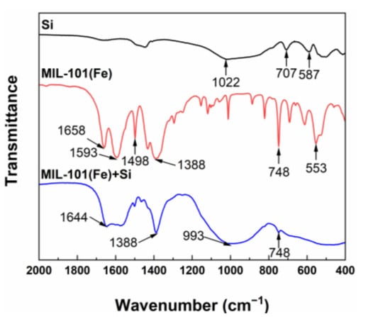
Figure 2.
ATR-FTIR spectra of Si (black), MIL-101(Fe) before adsorption (red) and MIL-101(Fe) after adsorbing silicic acid (blue).
XPS spectra were further performed to analyze the surface elements and chemical bonds of MIL-101(Fe). As seen from Figure 3, the C 1s peak could be divided into three peaks at 284.8 eV, 286.5 eV and 288.4 eV, which were attributed to C-C, C-O and C=O bonds, respectively. In addition, the peaks at 530.2 eV, 725.5 eV and 711.7 eV could be assigned to Fe-O bonds, Fe 2p1/2 and Fe 2p3/2, respectively. The Fe 2p1/2 and Fe 2p3/2 peaks with a satellite signal at 717.1 eV indicated the presence of Fe3+ within MIL-101(Fe) [55]. Peaks at 709.0 eV and 722.6 eV were not observed, suggesting that Fe2+ was not incorporated within MIL-101(Fe).
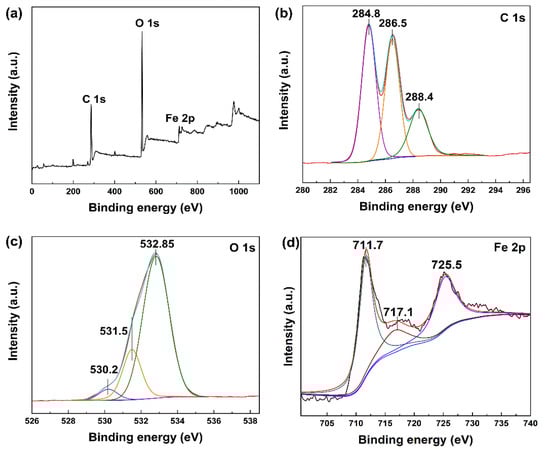
Figure 3.
XPS spectra of MIL-101(Fe): (a) survey scan, (b) C 1s (61.7%), (c) O 1s (35.2%) and (d) Fe 2p (3.1%).
3.3. Silicic Acid Adsorption of MIL-101(Fe)
3.3.1. Effect of Initial pH on Silicic Acid Adsorption
Figure 4a shows that the adsorption ability of MIL-101(Fe) to silicic acid was closely related to the initial pH of the sodium metasilica solution. Sodium metasilica mainly existed in the form of silicic acid molecules when the pH was below 9.83, resulting in a low adsorption capacity. When the pH reached 11.42, silicic acid existed in the form of ions, and the maximum adsorption capacity of MIL-101(Fe) to silicic acid reached 220.1 mgSiO2·g−1, revealing the high adsorption ability of MIL-101(Fe).
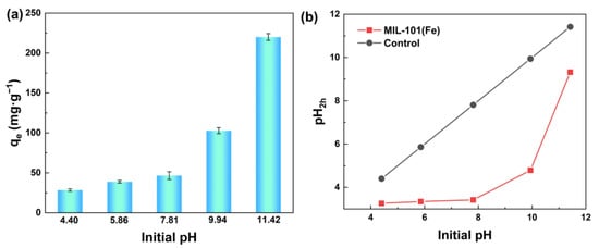
Figure 4.
(a) Effect of initial pH value on the adsorption performance of silicic acid; (b) pH value changing trend with time.
Figure 4b shows the changing trend of pH after adding MIL-101(Fe) to silicic acid solution under different pH conditions. Since both silicic acid and MIL-101(Fe) were negatively charged under alkaline conditions, the electrostatic attraction between them cannot explain the adsorption process well. Thus, we held the opinion that the high adsorption capacity of MIL-101(Fe) to silicic acid when the pH reached 9.83 might be due to the formation of Fe-OH groups, and then these groups reacted with -OH groups of silicic acid to form Fe-O-Si bonds. As the adsorption progressed continuously, the OH- in the solution was largely consumed, resulting in a significant decrease in the pH value after the adsorption.
3.3.2. Effect of Mixing Time and Kinetics on Silicic Acid Adsorption
The effect of mixing time shown in Figure 5a exhibited the fast adsorption of silicic acid on MIL-101(Fe). At the beginning of the adsorption process, the adsorption capacity increased rapidly, and then reached an invariable value. In the first 6 min, the adsorption capacity reached 125.9 mgSiO2·g−1, and then slowed down. The sample reached adsorption saturation at about 2 h, and the maximum adsorption capacity was 220.1 mgSiO2·g−1.
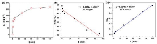
Figure 5.
(a) Adsorption capacity of silicic acid as a function of time; (b) Linear fit using the pseudo-first-order model; (c) Linear fit using the pseudo-second-order model.
To quantify the adsorption rate, the pseudo-first-order and pseudo-second-order equations were used to describe the process of adsorption, as show in Figure 5b,c. Model parameters such as the adsorption rate constant and equilibrium capacity could be calculated according to the intercept and slope of the fitted curve, as shown in Table 1. The pseudo-first-order and pseudo-second-order equations are normally expressed as Equations (3) and (4):
where qe (mg·g−1) and qt (mg·g−1) are the mass of silicic acid adsorbed at equilibrium and at time t (min), respectively; k1 and k2 are the adsorption rate constant; and t (min) is the mixing time.

Table 1.
Kinetic parameters of silicic acid adsorption process.
Table 1 shows that the coefficient of determination (R2) of both equations was greater than 0.99, indicating a good fit of the data. The adsorption process of MIL-101(Fe) to silicic acid was consistent with the pseudo-second-order kinetic equation due to its higher R2, indicating that chemisorption played a leading role during the adsorption process.
3.3.3. Effect of Initial Concentration and Adsorption Isotherm Study
Figure 6a exhibits the effect of the initial concentration of silicic acid on the adsorption performance. With the initial concentration increasing gradually, MIL-101(Fe) showed a rapid adsorption of silicic acid at the beginning, and then the adsorption rate decreased due to the limited active sites.
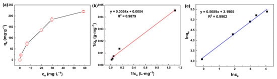
Figure 6.
(a) Adsorption capacity of silicic acid as a function of initial concentration; (b) Adsorption isotherms of the silicic acid adsorption process with the Langmuir isotherm model; (c) Adsorption isotherms of the silicic acid adsorption process with the Freundlich isotherm model.
Langmuir and Freundlich isotherm models [56] are normally expressed as Equations (5) and (6), respectively:
where qm (mg·g−1) is the maximal adsorption capacity, Ce (mg·L−1) is the equilibrium concentration and b (L·mg−1) is the equilibrium constant in the Langmuir model. Kf (mg·g−1) and n are the empirical coefficients in the Freundlich model.
In general, the Langmuir model assumes that only monomolecular layer adsorption occurs on the solid surface, which means that the adsorbate only interacts with the surface of the adsorbent, whereas the Freundlich model is applicable for multilayer adsorption, in which the adsorbates can interact with each other. It can be seen from Figure 6b,c and Table 2 that the R2 of both isotherm models are above 0.98, indicating that both monomolecular layer adsorption and multimolecular layer adsorption occurred during the adsorption of silicic acid on the surface of MIL-101(Fe). Thus, the adsorption process of silicic acid on MIL-101(Fe) involves two steps, as can be seen in Figure 7. First, silicic acid would bind directly to the unsaturated ion sites, which was the main mechanism of the rapid adsorption. As the adsorption proceeded, all the ion sites were occupied, resulting in the free silicic acid interacting with the adsorbed silicon to form Si-O-Si bonds.
Table 2.
Isotherm parameters of silicic acid adsorption process.
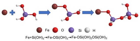
Figure 7.
Chemical diagram involving the two-step mechanism.
3.3.4. Effect of Temperature and Adsorption Thermodynamics Study
Figure 8a shows the effect of temperature on the adsorption of silicic acid. Obviously, the adsorption capacity to silicic acid increased with increasing temperature, indicating the benefits of heating on silicic acid adsorption.
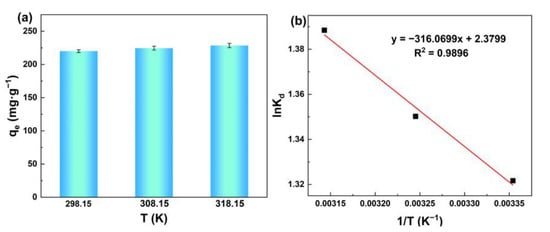
Figure 8.
(a) Adsorption capacity of silicic acid as a function of the temperature; (b) Fitting diagram of adsorption thermodynamic model of the silicic acid adsorption process.
The Van’t Hoff equation was applied to calculate thermodynamic parameters, as shown in Equations (7)–(9) [57]:
where k is the adsorption coeffcient; T (K) is the thermodynamic temperature; ΔH (kJ·mol−1) is the adsorption enthalpy; ΔS (J·mol−1·K−1) is the adsorption entropy; R (J·mol−1·K−1) is gas constant; and ΔG (kJ·mol−1) is the adsorption Gibbs free energy.
The fitting diagram and thermodynamic parameters can be seen in Figure 8b and Table 3. ΔH > 0 demonstrates that the adsorption process is endothermic, which means that the temperature rise is beneficial to accelerate the adsorption. ΔG < 0 indicates that the adsorption of silicic acid on MIL-101(Fe) can occur spontaneously. ΔS > 0 signifies that this adsorption is a process of entropy increase.
Table 3.
Thermodynamic parameters for silicic acid adsorption on MIL-101(Fe).
3.3.5. Adsorption Mechanism Study
Figure 9 shows the SEM images and elemental mapping of MIL-101(Fe) before and after the adsorption of silicic acid. The Si signal on the surface after the adsorption was significantly stronger than that before the adsorption, mainly due to the coverage of ion sites with silicic acid. The elemental composition of MIL-101(Fe) was also investigated using elemental mapping. Specifically, the weight concentration of oxygen on the surface increased from 22.70% to 25.11% while that of silicon increased from 0.62% to 3.34%. It can be proven using elemental composition analysis that silicic acid can not only bind to the unsaturated ion sites, but also interact with the adsorbed silicon, which was important evidence of the adsorption mechanism of silicic acid on MIL-101(Fe).
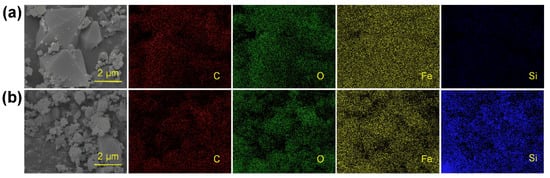
Figure 9.
SEM image and elemental mapping of MIL-101(Fe) before (a) and after (b) adsorption of silicic acid.
Recycle and regeneration experiments of MIL-101(Fe) were conducted immediately after the 2 h adsorption test. After washing MIL-101(Fe) with 0.05 M NaOH used as a regeneration reagent to release the silicic acid three times, ~75.6% of the adsorbent could be recycled and it showed ~60% recovery of the adsorption capacity.
3.3.6. Silica-Scale Mitigation on RO Membranes
To investigate the potential application of MIL-101(Fe) for silica-scaling mitigation in RO systems, a control experiment was designed. With other conditions being the same, the feed solution was pretreated with MIL-101(Fe) to adsorb silicic acid. As shown in Figure 10a, when the feed solution was not pretreated, the RO membrane showed a flux decline of around 23% after 24 h continuous filtration. Comparatively, when the feed solution was pretreated by the adsorption of MIL-101(Fe), the membrane flux only decreased by 13% after 24 h continuous filtration. Therefore, it can be concluded that if the feed solution is pretreated, less silica scale will form during the RO process, mainly because a large amount of silicic acid in the feed solution is adsorbed by MIL-101(Fe). Moreover, the membrane surface after filtration was observed by SEM, as presented in Figure 10b. In the non-pretreatment group, silica scale was concentrated on the membrane surface, while in the MIL-101(Fe) adsorption pretreatment group, there was a visible peak–valley structure and less scale on the RO membrane surface.
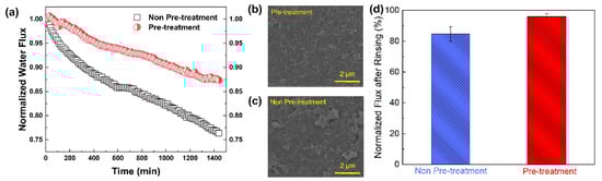
Figure 10.
(a) Normalized water flux as a function of filtration time for an RO membrane without pretreatment or with pre-treatment of the feed solution with MIL-101(Fe); (b,c) Surface SEM images of the RO membrane after filtration; (d) Normalized flux after chemical cleaning of the membranes that experienced the silica-scaling experiment.
Moreover, after 24 h of silica scaling, the membrane was cleaned with 0.1 M NaOH [18] with a flow rate of 1.2 L/min. After 2 h of cleaning, deionized water was used to rinse the membrane and filtration system. The membrane flux recovery rate was calculated using the initial flux and the flux after cleaning. As shown in Figure 10d, the water flux recovery rates of the membranes reached 96.1% for the pretreatment group and 84.7% for the non-pretreatment group, suggesting that chemical cleaning using an NaOH solution could effectively restore water flux by increasing silica solubility and depolymerizing colloidal silica [23]. In addition, the adsorption pretreatment of the feed solution favored an improvement in the efficiency of chemical cleaning, since the polymerization degree of silicic acid was greatly reduced after the adsorption [29]. Thus, the pretreatment of the feed solution based on the adsorption of MIL-101(Fe) became a more efficient approach for mitigating silica scale on RO membranes.
4. Conclusions
In this work, the metal-organic framework MIL-101(Fe) was successfully synthesized for the adsorption of silicic acid. Owing to its numerous unsaturated ion sites, MIL-101(Fe) exhibited excellent adsorption ability for silicic acid. The results of the adsorption experiment showed that the maximum adsorption capacity of MIL-101(Fe) for silicic acid could reach 220.1 mgSiO2·g−1. On account of the positive correlation between OH− and adsorbed silicic acid, the adsorption process of silicic acid on MIL-101(Fe) should involve two steps. Firstly, silicic acid binds directly to the unsaturated ion sites. As the adsorption proceeds, all the ion sites are occupied, resulting in the free silicic acid interacting with the adsorbed silicon to form Si-O-Si bonds. When the feed solution of RO systems was pretreated with the adsorption of MIL-101(Fe), the membrane flux only decreased by 13% after 24 h of continuous filtration, indicating that the adsorption treatment with MIL-101(Fe) could effectively be applied for silica-scaling mitigation in RO systems.
Author Contributions
R.G.: Data curation, Writing—original draft. J.Z.: Data curation, Methodology, Investigation. T.N.M.: Investigation. X.T.: Validation, Characterization. L.X.: Validation. S.Z.: Conceptualization, Writing—review & editing, Resources, Supervision. All authors have read and agreed to the published version of the manuscript.
Funding
This work is supported by grants S. Zhao received from the National Natural Science Foundation of China (No. 21776205).
Institutional Review Board Statement
Not applicable.
Data Availability Statement
Not applicable.
Acknowledgments
The authors would like to thank the Shiyanjia Lab (www.shiyanjia.com) for XRD (2022-12-12) and BET (2022-12-16) tests.
Conflicts of Interest
The authors declare no conflict of interest.
References
- Mauter, M.S.; Zucker, I.; Perreault, F.; Werber, J.R.; Kim, J.-H.; Elimelech, M. The role of nanotechnology in tackling global water challenges. Nat. Sustain. 2018, 1, 166–175. [Google Scholar] [CrossRef]
- Zhang, P.P.; Liao, Q.H.; Yao, H.Z.; Huang, Y.X.; Cheng, H.H.; Qu, L.T. Direct solar steam generation system for clean water production. Energy Storage Mater. 2019, 18, 429–446. [Google Scholar] [CrossRef]
- Shannon, M.A.; Bohn, P.W.; Elimelech, M.; Georgiadis, J.G.; Mariñas, B.J.; Mayes, A.M. Science and technology for water purification in the coming decades. Nature 2008, 452, 301–310. [Google Scholar] [CrossRef] [PubMed]
- Ezugbe, E.O.; Rathilal, S. Membrane Technologies in Wastewater Treatment: A Review. Membranes 2020, 10, 89. [Google Scholar] [CrossRef] [PubMed]
- Fane, A.G. A grand challenge for membrane desalination: More water, less carbon. Desalination 2018, 426, 155–163. [Google Scholar] [CrossRef]
- Goh, P.S.; Lau, W.J.; Othman, M.H.D.; Ismail, A.F. Membrane fouling in desalination and its mitigation strategies. Desalination 2018, 425, 130–155. [Google Scholar] [CrossRef]
- Jiang, S.; Li, Y.; Ladewig, B.P. A review of reverse osmosis membrane fouling and control strategies. Sci. Total Environ. 2017, 595, 567–583. [Google Scholar] [CrossRef]
- Zhao, J.J.; Wang, M.H.; Lababidi, H.M.S.; Al-Adwani, H.; Gleason, K.K. A review of heterogeneous nucleation of calcium carbonate and control strategies for scale formation in multi-stage flash (MSF) desalination plants. Desalination 2018, 442, 75–88. [Google Scholar] [CrossRef]
- Tzotzi, C.; Pahiadaki, T.; Yiantsios, S.G.; Karabelas, A.J.; Andritsos, N. A study of CaCO3 scale formation and inhibition in RO and NF membrane processes. J. Membr. Sci. 2007, 296, 171–184. [Google Scholar] [CrossRef]
- Lin, C.J.; Shirazi, S.; Rao, P.; Agarwal, S. Effects of operational parameters on cake formation of CaSO4 in nanofiltration. Water Res. 2006, 40, 806–816. [Google Scholar] [CrossRef]
- Park, D.J.; Supekar, O.D.; Greenberg, A.R.; Gopinath, J.T.; Bright, V.M. Real-time monitoring of calcium sulfate scale removal from RO desalination membranes using Raman spectroscopy. Desalination 2021, 497, 114736. [Google Scholar] [CrossRef]
- Warsinger, D.M.; Tow, E.W.; Maswadeh, L.A.; Connors, G.B.; Swaminathan, J.; Lienhard, V.J.H. Inorganic fouling mitigation by salinity cycling in batch reverse osmosis. Water Res. 2018, 137, 384–394. [Google Scholar] [CrossRef]
- Zaman, M.; Birkett, G.; Pratt, C.; Stuart, B.; Pratt, S. Downstream processing of reverse osmosis brine: Characterisation of potential scaling compounds. Water Res. 2015, 80, 227–234. [Google Scholar] [CrossRef]
- Sahachaiyunta, P.; Koo, T.; Sheikholeslami, R. Effect of several inorganic species on silica fouling in RO membranes. Desalination 2002, 144, 373–378. [Google Scholar] [CrossRef]
- Hater, W.; zum Kolk, C.; Braun, G.; Jaworski, J. The performance of anti-scalants on silica-scaling in reverse osmosis plants. Desalination Water Treat. 2013, 51, 908–914. [Google Scholar] [CrossRef]
- Hater, W.; zum Kolk, C.; Dupoiron, C.; Braun, G.; Harrer, T.; Gotz, T. Silica scaling on reverse osmosis membranes—Investigation and new test methods. Desalination Water Treat. 2011, 31, 326–330. [Google Scholar] [CrossRef]
- Kempter, A.; Gaedt, T.; Boyko, V.; Nied, S.; Hirsch, K. New insights into silica scaling on RO-membranes. Desalination Water Treat. 2013, 51, 899–907. [Google Scholar] [CrossRef]
- Park, Y.M.; Yeon, K.M.; Park, C.H. Silica treatment technologies in reverse osmosis for industrial desalination: A review. Environ. Eng. Res. 2020, 25, 819–829. [Google Scholar] [CrossRef]
- Liu, Q.; Xu, G.-R.; Das, R. Inorganic scaling in reverse osmosis (RO) desalination: Mechanisms, monitoring, and inhibition strategies. Desalination 2019, 468, 114065. [Google Scholar] [CrossRef]
- Bush, J.A.; Vanneste, J.; Gustafson, E.M.; Waechter, C.A.; Jassby, D.; Turchi, C.S.; Cath, T.Y. Prevention and management of silica scaling in membrane distillation using pH adjustment. J. Membr. Sci. 2018, 554, 366–377. [Google Scholar] [CrossRef]
- Tan, M.; Fang, L.; Zhang, B.; Zhao, Y.; Meng, X.; Li, F. Synergistic inhibition effect and mechanism of polycation and polyanion on colloidal silica. Colloids Surf. A-Physicochem. Eng. Asp. 2021, 610, 125701. [Google Scholar] [CrossRef]
- Rolf, J.; Cao, T.; Huang, X.; Boo, C.; Li, Q.; Elimelech, M. Inorganic Scaling in Membrane Desalination: Models, Mechanisms, and Characterization Methods. Environ. Sci. Technol. 2022, 56, 7484–7511. [Google Scholar] [CrossRef] [PubMed]
- Bush, J.A.; Vanneste, J.; Cath, T.Y. Comparison of membrane distillation and high-temperature nanofiltration processes for treatment of silica-saturated water. J. Membr. Sci. 2019, 570, 258–269. [Google Scholar] [CrossRef]
- Jiang, A.; Wang, H.; Lin, Y.; Cheng, W.; Wang, J. A study on optimal schedule of membrane cleaning and replacement for spiral-wound SWRO system. Desalination 2017, 404, 259–269. [Google Scholar] [CrossRef]
- Antony, A.; Low, J.H.; Gray, S.; Childress, A.E.; Le-Clech, P.; Leslie, G. Scale formation and control in high pressure membrane water treatment systems: A review. J. Membr. Sci. 2011, 383, 1–16. [Google Scholar] [CrossRef]
- Choudhury, R.R.; Gohil, J.M.; Mohanty, S.; Nayak, S.K. Antifouling, fouling release and antimicrobial materials for surface modification of reverse osmosis and nanofiltration membranes. J. Mater. Chem. A 2018, 6, 313–333. [Google Scholar] [CrossRef]
- Greenlee, L.F.; Lawler, D.F.; Freeman, B.D.; Marrot, B.; Moulin, P. Reverse osmosis desalination: Water sources, technology, and today’s challenges. Water Res. 2009, 43, 2317–2348. [Google Scholar] [CrossRef]
- Milne, N.A.; O’Reilly, T.; Sanciolo, P.; Ostarcevic, E.; Beighton, M.; Taylor, K.; Mullett, M.; Tarquin, A.J.; Gray, S.R. Chemistry of silica scale mitigation for RO desalination with particular reference to remote operations. Water Res. 2014, 65, 107–133. [Google Scholar] [CrossRef]
- Guan, Y.-F.; Marcos-Hernández, M.; Lu, X.; Cheng, W.; Yu, H.-Q.; Elimelech, M.; Villagrán, D. Silica Removal Using Magnetic Iron–Aluminum Hybrid Nanomaterials: Measurements, Adsorption Mechanisms, and Implications for Silica Scaling in Reverse Osmosis. Environ. Sci. Technol. 2019, 53, 13302–13311. [Google Scholar] [CrossRef]
- Naren, G.; Ohashi, H.; Okaue, Y.; Yokoyama, T. Adsorption kinetics of silicic acid on akaganeite. J. Colloid Interface Sci. 2013, 399, 87–91. [Google Scholar] [CrossRef]
- Qiu, S.L.; Xue, M.; Zhu, G.S. Metal-organic framework membranes: From synthesis to separation application. Chem. Soc. Rev. 2014, 43, 6116–6140. [Google Scholar] [CrossRef]
- Lian, X.; Erazo-Oliveras, A.; Pellois, J.-P.; Zhou, H.-C. High efficiency and long-term intracellular activity of an enzymatic nanofactory based on metal-organic frameworks. Nat. Commun. 2017, 8, 2075. [Google Scholar] [CrossRef] [PubMed]
- Kim, J.; Chen, B.; Reineke, T.M.; Li, H.; Eddaoudi, M.; Moler, D.B.; O’Keeffe, M.; Yaghi, O.M. Assembly of Metal−Organic Frameworks from Large Organic and Inorganic Secondary Building Units: New Examples and Simplifying Principles for Complex Structures. J. Am. Chem. Soc. 2001, 123, 8239–8247. [Google Scholar] [CrossRef] [PubMed]
- Eddaoudi, M.; Li, H.L.; Yaghi, O.M. Highly porous and stable metal-organic frameworks: Structure design and sorption properties. J. Am. Chem. Soc. 2000, 122, 1391–1397. [Google Scholar] [CrossRef]
- Du, Y.J.; Jia, X.T.; Zhong, L.; Jiao, Y.; Zhang, Z.J.; Wang, Z.Y.; Feng, Y.X.; Bilal, M.; Cui, J.D.; Jia, S.R. Metal-organic frameworks with different dimensionalities: An ideal host platform for enzyme@MOF composites. Coord. Chem. Rev. 2022, 454, 214327. [Google Scholar] [CrossRef]
- Ma, X.J.; Chai, Y.T.; Li, P.; Wang, B. Metal-Organic Framework Films and Their Potential Applications in Environmental Pollution Control. Acc. Chem. Res. 2019, 52, 1461–1470. [Google Scholar] [CrossRef] [PubMed]
- Herm, Z.R.; Swisher, J.A.; Smit, B.; Krishna, R.; Long, J.R. Metal−Organic Frameworks as Adsorbents for Hydrogen Purification and Precombustion Carbon Dioxide Capture. J. Am. Chem. Soc. 2011, 133, 5664–5667. [Google Scholar] [CrossRef]
- Ding, M.L.; Flaig, R.W.; Jiang, H.L.; Yaghi, O.M. Carbon capture and conversion using metal-organic frameworks and MOF-based materials. Chem. Soc. Rev. 2019, 48, 2783–2828. [Google Scholar] [CrossRef]
- Xu, M.; Feng, L.; Yan, L.-N.; Meng, S.-S.; Yuan, S.; He, M.-J.; Liang, H.; Chen, X.-Y.; Wei, H.-Y.; Gu, Z.-Y.; et al. Discovery of precise pH-controlled biomimetic catalysts: Defective zirconium metal–organic frameworks as alkaline phosphatase mimics. Nanoscale 2019, 11, 11270–11278. [Google Scholar] [CrossRef]
- Chen, B.; Eddaoudi, M.; Hyde, S.T.; O’Keeffe, M.; Yaghi, O.M. Interwoven Metal-Organic Framework on a Periodic Minimal Surface with Extra-Large Pores. Science 2001, 291, 1021–1023. [Google Scholar] [CrossRef]
- McDonald, T.M.; Lee, W.R.; Mason, J.A.; Wiers, B.M.; Hong, C.S.; Long, J.R. Capture of Carbon Dioxide from Air and Flue Gas in the Alkylamine-Appended Metal–Organic Framework mmen-Mg2(dobpdc). J. Am. Chem. Soc. 2012, 134, 7056–7065. [Google Scholar] [CrossRef]
- Jia, J.; Xu, F.; Long, Z.; Hou, X.; Sepaniak, M.J. Metal–organic framework MIL-53(Fe) for highly selective and ultrasensitive direct sensing of MeHg+. Chem. Commun. 2013, 49, 4670–4672. [Google Scholar] [CrossRef]
- Zhao, X.L.; Zhao, J.; Sun, Y.Y.; Ouyang, H.; Chen, N.; Ren, J.; Li, Y.; Chen, S.; Yang, D.J.; Xing, B.S. Selenite capture by MIL-101(Fe) through Fe-O-Se bonds at free coordination Fe sites. J. Hazard. Mater. 2022, 424, 127715. [Google Scholar] [CrossRef]
- Ni, P.; Fox, J.T. Metal organic frameworks synthesized with green chemistry for the removal of silicic acid from aqueous solutions. Sep. Purif. Technol. 2021, 272, 118118. [Google Scholar] [CrossRef]
- Ferey, G.; Mellot-Draznieks, C.; Serre, C.; Millange, F.; Dutour, J.; Surble, S.; Margiolaki, I. A chromium terephthalate-based solid with unusually large pore volumes and surface area. Science 2005, 309, 2040–2042. [Google Scholar] [CrossRef]
- Wang, D.B.; Jia, F.Y.; Wang, H.; Chen, F.; Fang, Y.; Dong, W.B.; Zeng, G.M.; Li, X.M.; Yang, Q.; Yuan, X.Z. Simultaneously efficient adsorption and photocatalytic degradation of tetracycline by Fe-based MOFs. J. Colloid Interface Sci. 2018, 519, 273–284. [Google Scholar] [CrossRef]
- Xie, Q.Y.; Li, Y.; Lv, Z.L.; Zhou, H.; Yang, X.J.; Chen, J.; Guo, H. Effective Adsorption and Removal of Phosphate from Aqueous Solutions and Eutrophic Water by Fe-based MOFs of MIL-101. Sci. Rep. 2017, 7, 3316. [Google Scholar] [CrossRef]
- Latroche, M.; Surble, S.; Serre, C.; Mellot-Draznieks, C.; Llewellyn, P.L.; Lee, J.H.; Chang, J.S.; Jhung, S.H.; Ferey, G. Hydrogen storage in the giant-pore metal-organic frameworks MIL-100 and MIL-101. Angew. Chem.-Int. Ed. 2006, 45, 8227–8231. [Google Scholar] [CrossRef]
- Liu, R.J.; Xie, Y.D.; Cui, K.F.; Xie, J.; Zhang, Y.X.; Huang, Y.P. Adsorption behavior and adsorption mechanism of glyphosate in water by amino-MIL-101(Fe). J. Phys. Chem. Solids 2022, 161, 110403. [Google Scholar] [CrossRef]
- Thanh, H.T.M.; Phuong, T.T.T.; Hang, P.T.L.; Toan, T.T.T.; Tuyen, T.N.; Mau, T.X.; Khieu, D.Q. Comparative study of Pb(II) adsorption onto MIL-101 and Fe-MIL-101 from aqueous solutions. J. Environ. Chem. Eng. 2018, 6, 4093–4102. [Google Scholar] [CrossRef]
- Tang, J.; Yang, M.; Yang, M.; Wang, J.J.; Dong, W.J.; Wang, G. Heterogeneous Fe-MIL-101 catalysts for efficient one-pot four-component coupling synthesis of highly substituted pyrroles. New J. Chem. 2015, 39, 4919–4923. [Google Scholar] [CrossRef]
- Wu, Y.P.; Zhou, C.L.; Xue, S.S.; Li, C.; Lin, Y.H.; Zheng, Z.H.; Ding, X.B. Preparation and Oil Absorption of Magnetic and Porous Materials Based on Carboxymethyl Cellulose Sodium Modified Polyurethane Foams. Acta Polym. Sin. 2017, 516–523. [Google Scholar] [CrossRef]
- Lin, L.H.; Lee, H.T. A new modified silicone-TiO2 polymer composite film and its photocatalytic degradation. J. Appl. Polym. Sci. 2006, 102, 3341–3344. [Google Scholar] [CrossRef]
- Zheng, S.X.; Guo, S.; Wang, L. Influence of curing temperature on SiO2/resole hybrid coating films. J. Sol-Gel Sci. Technol. 2022, 101, 185–192. [Google Scholar] [CrossRef]
- He, L.; Dong, Y.N.; Zheng, Y.N.; Jia, Q.M.; Shan, S.Y.; Zhang, Y.Q. A novel magnetic MIL-101(Fe)/TiO2 composite for photo degradation of tetracycline under solar light. J. Hazard. Mater. 2019, 361, 85–94. [Google Scholar] [CrossRef] [PubMed]
- Ezzati, R. Derivation of Pseudo-First-Order, Pseudo-Second-Order and Modified Pseudo-First-Order rate equations from Langmuir and Freundlich isotherms for adsorption. Chem. Eng. J. 2020, 392, 123705. [Google Scholar] [CrossRef]
- Lima, E.C.; Gomes, A.A.; Tran, H.N. Comparison of the nonlinear and linear forms of the van’t Hoff equation for calculation of adsorption thermodynamic parameters (Delta S degrees and Delta H degrees). J. Mol. Liq. 2020, 311, 113315. [Google Scholar] [CrossRef]
Disclaimer/Publisher’s Note: The statements, opinions and data contained in all publications are solely those of the individual author(s) and contributor(s) and not of MDPI and/or the editor(s). MDPI and/or the editor(s) disclaim responsibility for any injury to people or property resulting from any ideas, methods, instructions or products referred to in the content. |
© 2023 by the authors. Licensee MDPI, Basel, Switzerland. This article is an open access article distributed under the terms and conditions of the Creative Commons Attribution (CC BY) license (https://creativecommons.org/licenses/by/4.0/).