
Development and Industrial-Scale Fabrication of Next-Generation Low-Energy Membranes for Desalination


Abstract
:1. Introduction
2. Materials and Methods
2.1. Materials
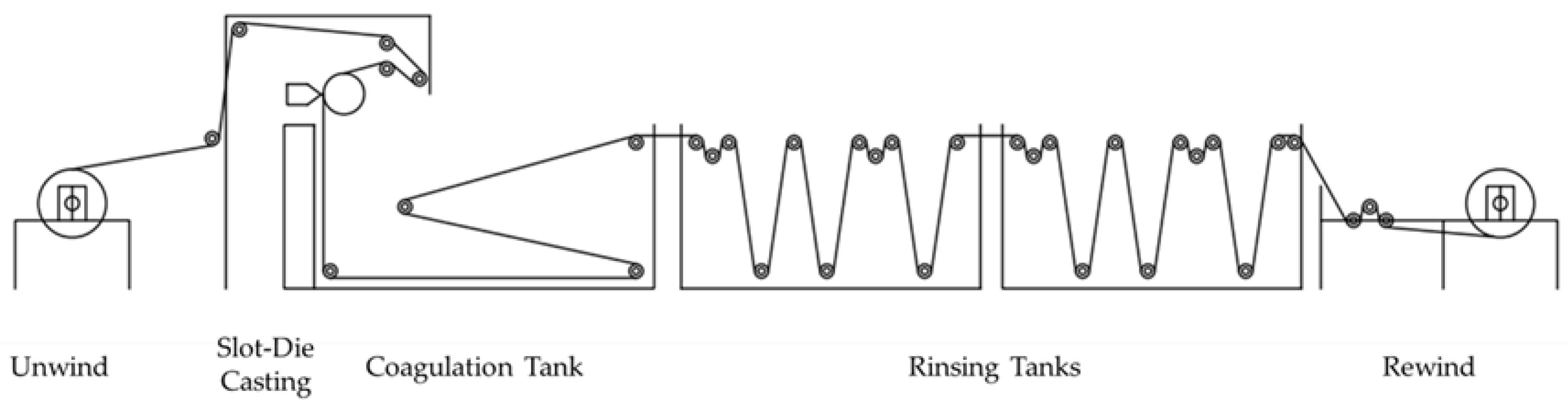
2.2. Fabrication of Flat-Sheet Membranes
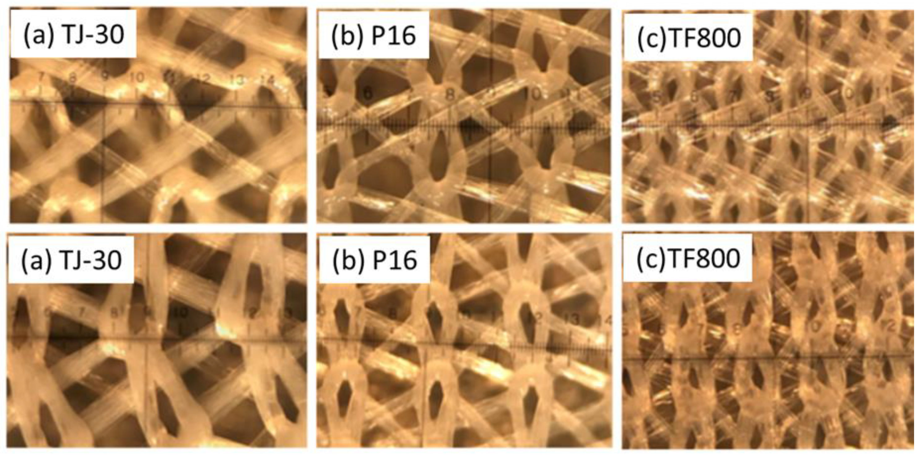
2.3. Characterization of Membrane Coupons
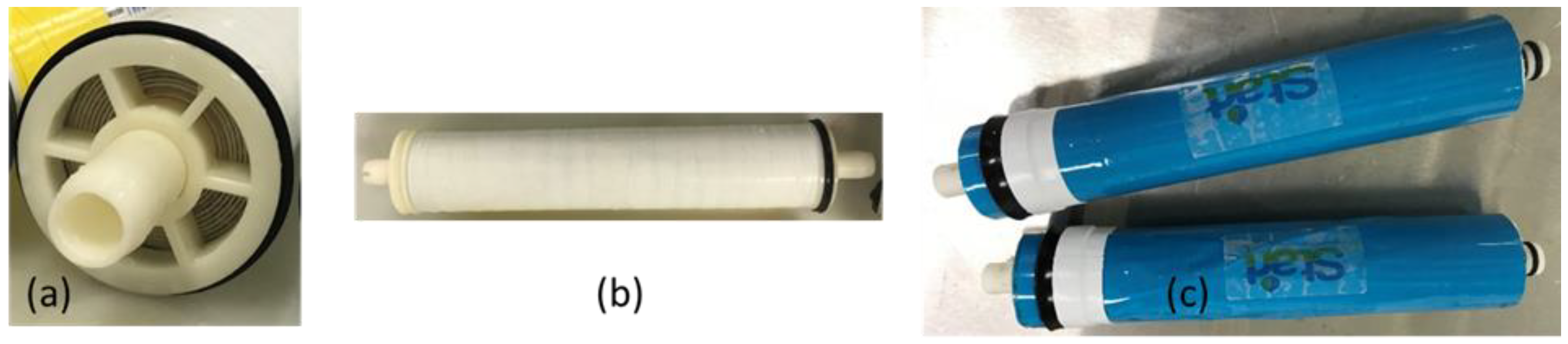
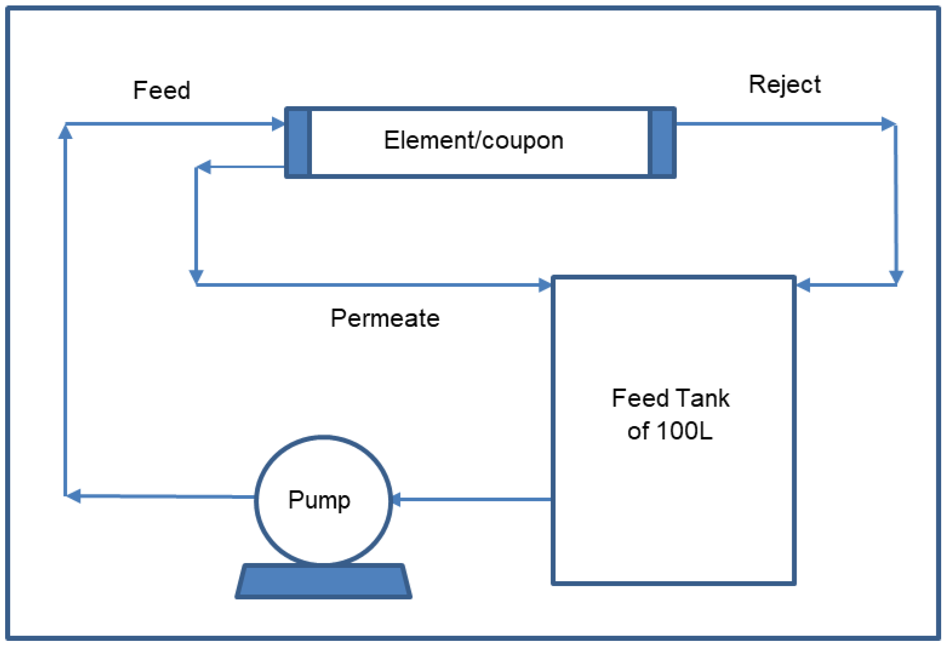
2.4. Spiral-Wound Module Testing
3. Results and Discussions
4. Conclusions
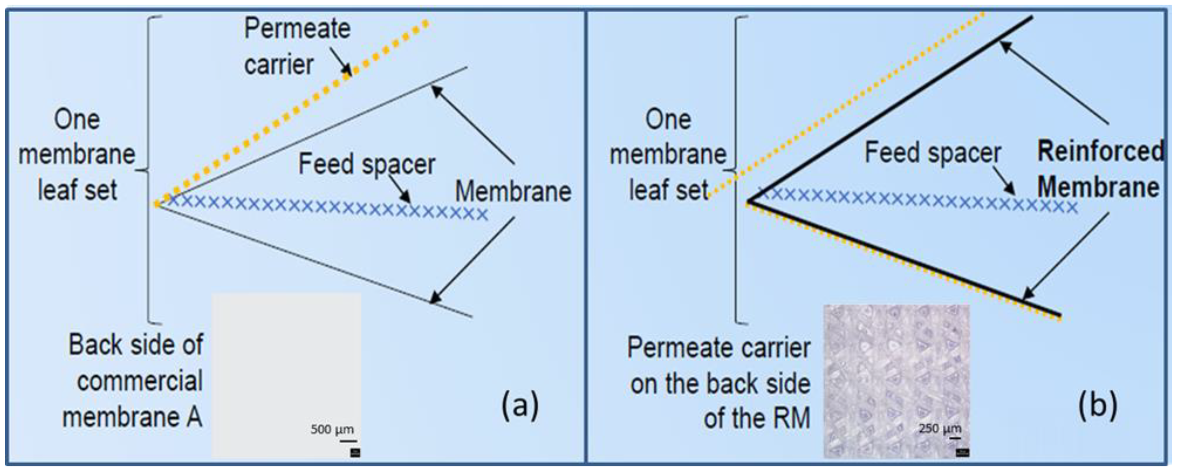
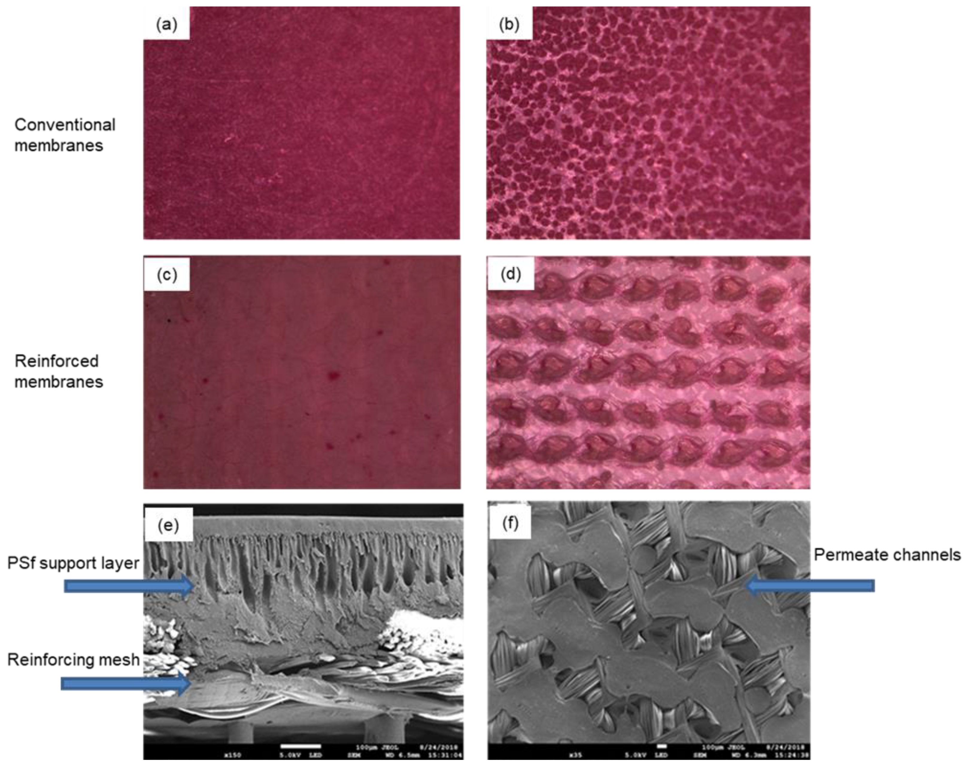
- We successfully developed a novel process to fabricate reinforced flat-sheet membranes on permeate carrier materials, instead of conventional non-woven fabric materials.
- The reinforced membrane fabrication process can be translated to an industrial-scale fabrication line for large-scale manufacturing.
- Through preliminary trials, we demonstrated that the reinforced PSf support layer is amenable to interfacial polymerization, leading to a defect-free thin-film composite polyamide coating with high flux and salt rejection.
- Preliminary experiments successfully validated the concept of reinforced membrane fabrication on the industrial-scale membrane production line and will pave the way for large-scale production once the proof-of-value is established through large-scale pilot testing.
- A very high flux of 65 LMH and >90% salt rejection was observed for the RO membranes prepared on the TF800 permeate carrier with a mesh size of 100 μm. While further study using the TF800 was limited by the high price and availability of the materials, cheaper source identification and process optimization trials will ensue in future studies.
- The TFC coating on the reinforced membranes resulted in a flux comparable to commercial RO membranes (1–1.5 LMH/bar) and rejection of up to 95 % on coupon-level testing and up to 87% on 2514 element testing.
- An overall membrane leaf set thickness reduction of 8–10% was successfully achieved, and the resulting free volume enables the packing of a much larger membrane area in a given volume in commercial modules (1812, 2514, 4004, or 8040).
Author Contributions
Funding
Institutional Review Board Statement
Data Availability Statement
Conflicts of Interest
References
- Issaoui, M.; Jellali, S.; Zorpas, A.A.; Dutournie, P. Membrane technology for sustainable water resources management: Challenges and future projections. Sustain. Chem. Pharm. 2022, 25, 100590. [Google Scholar] [CrossRef]
- Kurihara, M. Current status and future trend of dominant commercial reverse osmosis membranes. Membranes 2021, 11, 906. [Google Scholar] [CrossRef] [PubMed]
- Park, J.; Lee, S. Desalination technology in South Korea: A comprehensive review of technology trends and future outlook. Membranes 2022, 12, 204. [Google Scholar] [CrossRef] [PubMed]
- Karabelas, A.J.; Koutsou, C.P.; Kostoglou, M.; Sioutopoulos, D.C. Analysis of specific energy consumption in reverse osmosis desalination processes. Desalination 2018, 431, 15–21. [Google Scholar] [CrossRef]
- Leon, F.; Ramos, A.; Perez-Baez, S.O. Optimization of energy efficiency, operation costs, carbon footprint and ecological footprint with reverse osmosis membranes in seawater desalination plants. Membranes 2021, 11, 781. [Google Scholar] [CrossRef]
- Li, Y.; Qi, S.; Tian, M.; Widjajanti, W.; Wang, R. Fabrication of aquaporin-based biomimetic membrane for seawater desalination. Desalination 2019, 467, 103–112. [Google Scholar] [CrossRef]
- Lim, Y.J.; Ma, Y.; Chew, J.W.; Wang, R. Assessing the potential of highly permeable reverse osmosis membranes for desalination: Specific energy and footprint analysis. Desalination 2022, 533, 115771. [Google Scholar] [CrossRef]
- Touati, K.; Dudchenko, A.V.; Mauter, M.S.; Rahaman, M.S. Desalination process design assisted by osmotic power for high water recovery and low energy consumption. ACS Sustain. Chem. Eng. 2022, 10, 2409–2419. [Google Scholar] [CrossRef]
- Ruiz-Garcia, A.; Pestana, I.D.L.N. Feed spacer geometries and permeability coefficients. effect on the performance in BWRO spiral-wound membrane modules. Water 2019, 11, 152. [Google Scholar] [CrossRef] [Green Version]
- Ruiz-Garcia, A.; Nuez, I. Performance assessment of SWRO spiral-wound membrane modules with different feed spacer dimensions. Processes 2020, 8, 692. [Google Scholar] [CrossRef]
- Voutchkov, N. Energy use for membrane seawater desalination—Current status and trends. Desalination 2018, 431, 2–14. [Google Scholar] [CrossRef]
- Cohen-Tanugi, D.; McGovern, R.K.; Dave, S.H.; Lienhard, J.H.; Grossman, J.C. Quantifying the potential of ultra-permeable membranes for water desalination. Energy Environ. Sci. 2014, 7, 1134. [Google Scholar] [CrossRef] [Green Version]
- Okamoto, Y.; Lienhard, J.H. How RO membrane permeability and other performance factors affect process cost and energy use: A review. Desalination 2019, 470, 114064. [Google Scholar] [CrossRef]
- She, Q.; Wei, J.; Ma, N.; Sim, V.; Fane, A.G.; Wang, R.; Tang, C.Y. Fabrication and characterization of fabric-reinforced pressure retarded osmosis membranes for osmotic power harvesting. J. Membr. Sci. 2016, 504, 75–88. [Google Scholar] [CrossRef]
- Sun, Y.; Cheng, L.; Shintani, T.; Tanaka, Y.; Takahashi, T.; Itai, T.; Wang, S.; Fang, L.; Matsuyama, H. Development of high-flux and robust reinforced aliphatic polyketone thin-film composite membranes for osmotic power generation: Role of reinforcing materials. Ind. Eng. Chem. Res. 2018, 57, 13528–13538. [Google Scholar] [CrossRef]
- Shin, M.-G.; Choi, W.; Lee, J.-H. Highly selective and pH-stable reverse osmosis membranes prepared via layered interfacial polymerization. Membranes 2022, 12, 156. [Google Scholar] [CrossRef] [PubMed]
- Zhang, Z.; Atia, A.A.; Andrés-Mañas, J.A.; Zaragoza, G.; Fthenakis, V. Comparative techno-economic assessment of osmotically-assisted reverse osmosis and batch-operated vacuum-air-gap membrane distillation for high-salinity water desalination. Desalination 2022, 532, 115737. [Google Scholar] [CrossRef]
- Matta, S.M.; Selam, M.A.; Manzoor, H.; Adham, S.; Shon, H.K.; Castier, M.; Abdel-Wahab, A. Predicting the performance of spiral-wound membranes in pressure retarded osmosis processes. Renew. Energy 2022, 189, 66–77. [Google Scholar] [CrossRef]
- Gu, B.; Adjiman, C.S.; Xu, X.Y. Correlations for concentration polarization and pressure drop in spacer-filled RO membrane modules based on CFD simulations. Membranes 2021, 11, 338. [Google Scholar] [CrossRef]
- Tang, C.Y.; She, Q.H.; Ma, N.; Wei, J.; Sim, S.T.V.; Fane, A.G. Reinforced Membranes for Producing Osmotic Power in Pressure Retarded Osmosis. U.S. Patent US2015/0217238A1, 6 August 2015. [Google Scholar]
- Gudipati, C.; Goh, L.M.; Ooi, S.T.; Ng, K.S.; Thong, Z.; Li, W.P. Low Energy Reinforced Membrane for Pressure Driven Application. PCT Patent WO2020226569A1, 12 June 1990. [Google Scholar]
- Wei, J.; Qiu, C.Q.; Tang, C.Y.; Wang, R.; Fane, A.G. Synthesis and characterization of flat-sheet thin film composite forward osmosis membranes. J. Membr. Sci. 2011, 372, 292–302. [Google Scholar] [CrossRef]
- Han, J.-C.; Xing, X.-Y.; Wang, J.; Wu, Q.-Y. Preparation and properties of thin-film composite forward osmosis membranes supported by cellulose triacetate porous substrate via a nonsolvent-thermally induced phase separation process. Membranes 2022, 12, 412. [Google Scholar] [CrossRef] [PubMed]
- Zhang, M.; Hu, X.; Peng, L.; Zhou, S.; Xie, S.; Song, X.; Gao, C. The intrinsic parameters of the polyamide nanofilm in thin-film composite reverse osmosis (TFC-RO) membranes: The impact of monomer concentration. Membranes 2022, 12, 417. [Google Scholar] [CrossRef] [PubMed]


| Phase-Inversion Line Conditions | |
|---|---|
| Dope solution | PSf/LiBr/NMP |
| (wt. %) | 17/2/81 |
| Line speed (m/min) | 2.3 |
| Dope flow rate (mL/min) | 500 |
| Pre-wetting solution | DI |
| Pre-wetting solution flow rate (mL/min) | 300 |
| Dope temperature (°C) | Room temperature (~20) |
| Coagulation bath temperatures (°C) | Room temperature (~20) |
| No. | Membrane Backing | Pre-Wetting Solution | Flux (L m−2 h−1) | Rejection (%) |
|---|---|---|---|---|
| 1 | TJ-030 | 2.5 wt.% SLS | Very high | Negligible |
| 2 | TJ-030 | 0.2 wt.% SLS | 29.2 | 82.8 |
| 3 | TJ-030 | 80 wt.% NMP, 20 wt.% water | 89.1 | 25.9 |
| 4 | TJ-030 | 20 wt.% NMP, 80 wt.% water | 27.9 | 93.6 |
| 5 | TJ-030 | DI | 22.0 | 95.0 |
| 6 | TJ-030 | None | Very high | Negligible |
| 7 | Non-woven fabric | None | 25.8 | 98.2 |
| Membrane Backing | Average Mesh Hole Size | Pre-Wetting Solution | Flux (L m−2 h−1) | Rejection (%) | MWCO (kDa) | Change in Membrane Thickness (%) |
|---|---|---|---|---|---|---|
| TJ-030 | ≈400 microns | DI | 21.98 ± 4.10 | 95.0 ± 2.7 | 53.9 | −1.4% |
| P16 | ≈300 microns | DI | 40.97 ± 3.80 | 94.1 ± 9.5 | 96.0 | −8.6% |
| TF800 | ≈100 microns | DI | 65.28 ± 6.11 | 91.6 ± 10.5 | 36.9 | −5.8% |
| Non-woven | NA | None | 25.78 ± 2.78 | 98.2 ± 0.9 | 54.0 | 0% |
| / | Coupon Testing | 1812 Element | 2514 Element | |||||
|---|---|---|---|---|---|---|---|---|
| Membrane Backing | Pre-Wetting Solution | % Change in Thickness | Flux (L m−2 h−1) | Rejection (%) | Flux (LPM) | Rejection (%) | Flux (LPM) | Rejection (%) |
| P16 | DI | −7.37% | 40.97 ± 3.76 | 94.1 ± 9.5 | 0.032 ± 0.012 | 79.5 ± 10.1 | 0.279 ± 0.054 | 87.7 ± 5.4 |
| Non-woven | None | 0% | 25.78 ± 2.78 | 98.2 ± 0.9 | NA | NA | NA | NA |
Publisher’s Note: MDPI stays neutral with regard to jurisdictional claims in published maps and institutional affiliations. |
© 2022 by the authors. Licensee MDPI, Basel, Switzerland. This article is an open access article distributed under the terms and conditions of the Creative Commons Attribution (CC BY) license (https://creativecommons.org/licenses/by/4.0/).
Share and Cite
Goh, L.M.; Thong, Z.; Li, W.P.; Ooi, S.T.; Esa, F.; Ng, K.S.; Dhalla, A.; Gudipati, C. Development and Industrial-Scale Fabrication of Next-Generation Low-Energy Membranes for Desalination. Membranes 2022, 12, 540. https://doi.org/10.3390/membranes12050540
Goh LM, Thong Z, Li WP, Ooi ST, Esa F, Ng KS, Dhalla A, Gudipati C. Development and Industrial-Scale Fabrication of Next-Generation Low-Energy Membranes for Desalination. Membranes. 2022; 12(5):540. https://doi.org/10.3390/membranes12050540
Chicago/Turabian StyleGoh, Li May, Zhiwei Thong, Weikun Paul Li, Shu Ting Ooi, Farhanah Esa, Kok Seng Ng, Adil Dhalla, and Chakravarthy Gudipati. 2022. "Development and Industrial-Scale Fabrication of Next-Generation Low-Energy Membranes for Desalination" Membranes 12, no. 5: 540. https://doi.org/10.3390/membranes12050540
APA StyleGoh, L. M., Thong, Z., Li, W. P., Ooi, S. T., Esa, F., Ng, K. S., Dhalla, A., & Gudipati, C. (2022). Development and Industrial-Scale Fabrication of Next-Generation Low-Energy Membranes for Desalination. Membranes, 12(5), 540. https://doi.org/10.3390/membranes12050540