Abstract
A porous substrate plays an important role in constructing a thin-film composite forward osmosis (TFC-FO) membrane. To date, the morphology and performance of TFC-FO membranes are greatly limited by porous substrates, which are commonly fabricated by non-solvent induced phase separation (NIPS) or thermally induced phase separation (TIPS) processes. Herein, a novel TFC-FO membrane has been successfully fabricated by using cellulose triacetate (CTA) porous substrates, which are prepared using a nonsolvent-thermally induced phase separation (N-TIPS) process. The pore structure, permeability, and mechanical properties of CTA porous substrate are carefully investigated via N-TIPS process (CTAN-TIPS). As compared with those via NIPS and TIPS processes, the CTAN-TIPS substrate shows a smooth surface and a cross section combining interconnected pores and finger-like macropores, resulting in the largest water flux and best mechanical property. After interfacial polymerization, the obtained TFC-FO membranes are characterized in terms of their morphology and intrinsic transport properties. It is found that the TFC-FO membrane supported by CTAN-TIPS substrate presents a thin polyamide film full of nodular and worm-like structure, which endows the FO membrane with high water permeability and selectivity. Moreover, the TFC-FO membrane supported by CTAN-TIPS substrate displays a low internal concentration polarization effect. This work proposes a new insight into preparing TFC-FO membrane with good overall performance.
1. Introduction
Membrane-based technology is booming in order to deal with the worldwide water scarcity due to its superior and distinct advantages of high water quality, excellent separation efficiency, and environmental friendliness [,,,]. Among others, forward osmosis (FO) refers to a promising membrane-based process for water purification and seawater desalination [,,]. The FO process is driven by osmotic pressure difference, during which water molecules spontaneously pass through a permselective membrane from a feed solution to a draw solution. Thus, the FO process is characterized by low energy consumption and a low membrane-fouling tendency as compared with external pressure-driven membrane-based processes [,].
Nowadays, thin-film composite (TFC) membrane is the most commonly used FO membrane, consisting of a selective layer and a porous substrate [,,]. Among others, the porous substrate plays an important role in regulating the structure and the performance of TFC-FO membrane. For example, the surface-pore size and porosity of the substrate deeply affects the morphology of the selective layer through interfacial polymerization []. On the other hand, the porous substrate as the mass transfer channels is directly connected to the water permeability. An internal concentration polarization (ICP) will be caused by the diluted or concentrated solution inside the porous s ubstrate, which brings about the decreasing of the effective osmotic pressure difference between the two sides of the selective layer [,,,,]. As a consequence, the water flux of TFC-FO membrane is severely reduced. ICP is mainly dependent on the substrate structure, which is described by the structural parameter (S). ICP can be alleviated by using a substrate with small thickness (l), high porosity (ε), and low tortuosity (τ) (S = l·τ/ε). Therefore, a satisfactory porous substrate is key for a TFC-FO membrane with excellent comprehensive performance, such as high water permeability, low reverse salt flux, high selectivity, and good physical strength.
By far, a porous substrate is mainly constructed through a non-solvent induced-phase separation (NIPS) process, which is carried out at low temperature and has high accessibility in manufacturing [,]. The substrates prepared using a NIPS process usually have a smooth surface with nanoscale pores suitable to be composite with the PA layer through interfacial polymerization. However, an asymmetric structure as the characteristic of the substrate via NIPS always results in a poor mechanical strength. In contrast, the substrates via thermally induced phase separation (TIPS) method show a symmetric structure and a good physical strength [,]. Yabuno et al., prepared a TFC-FO membrane using polyvinylidene difluoride substrate via TIPS process, which presented a higher physical strength compared to that using polysulfone substrate via NIPS method []. Recently, nonsolvent-thermally induced phase separation (N-TIPS) has been put forward to tailor the substrate structure by combining both advantages of NIPS and TIPS processes [,,,]. N-TIPS process not only can be operated at moderate condition, but also can be modulated by various parameters. Moreover, the substrate via N-TIPS demonstrates a smooth and porous surface, symmetric structure, and good mechanical strength, which are beneficial for TFC-FO membrane with excellent performance. However, using a N-TIPS method to prepare TFC-FO membrane substrate still lacks deep exploration. It is worthwhile to develop a new kind of TFC-FO membrane supported by the porous substrates via N-TIPS, and further investigate its structure–performance relationship.
Herein, a novel TFC-FO membrane was fabricated with a cellulose triacetate (CTA) porous substrate via N-TIPS method. CTA is a popular membrane material derived from the natural cellulose. Thus, CTA membranes attract extensive attention due to their great biocompatibility, excellent hydrophilicity, and outstanding antifouling property compared with most other polymeric membranes [,,,]. In this work, we comprehensively investigated the structure and property of CTA substrate via N-TIPS, and compared with those via NIPS and TIPS processes. Moreover, the morphology and performance of the TFC-FO membranes were also studied in detail and correlated with the corresponding porous substrates. Detailed discussion was focused on the water permeability, reverse salt flux, and structure parameter of TFC-FO membranes in light of the porous substrates prepared by different phase separation processes. The obtained TFC-FO membrane with CTA substrate via the N-TIPS process demonstrated excellent comprehensive performance that could be promising for many applications.
2. Experimental Section
2.1. Materials
Cellulose triacetate (CTA, Mw = 1.2 × 10⁵ Da; Acros Organics, Shanghai, China) was dried under vacuum at 60 °C for 4 h to remove moisture before usage. Dimethyl sulfone (DMSO2, 99% purity) was utilized as a solvent, supplied by Dakang Chemicals Co., Hangzhou, China. Polyethylene glycol (PEG400, Mw = 380~430, AR grade) as an additive was employed by Sinopharm Chemical Reagent Co. Ltd., Shanghai, China. Polyvinyl alcohol (PVA, Mw = 78,243~78,475) and trimesoyl chloride (TMC, ~98%) were supplied by Aladdin. m-Phenylenediamine (MPD, >99%, Acros Organics, Shanghai, China) and Isopar-G (Exxon Mobil Chemical Co., Shanghai, China) were used as received. Other chemicals including sodium hypochlorite (NaClO), sodium bisulfate (NaHSO3) and sodium chloride (NaCl) were purchased from Sinopharm Chemical Reagent Co. Ltd., Shanghai, China.
2.2. Fabrication of TFC-FO Membranes
2.2.1. Preparation of CTA Porous Substrates
First, 10 wt% CTA was added into DMSO2/PEG400 mixtures (the weight ratio was 70:30) and stirred at 160 °C to obtain a homogeneous solution. After it was degassed, the casting solution was rapidly poured onto a polyester-screen-wrapped mold, which was preheated at 140 °C. Then, a liquid film was cast on the polyester screen using a casting knife with a height of 200 μm. It should be mentioned that the polyester screen was pretreated by infiltration in a 5 wt% PVA solution for 30 min. Then, three kinds of phase-separation methods were introduced to obtain different CTA porous substrates, and the corresponding preparation conditions were listed in Table 1 according to our previous work [,,]. CTATIPS, CTAN-TIPS, and CTAN-TIPS represent the CTA porous substrates prepared via TIPS, NIPS, and N-TIPS methods, respectively.

Table 1.
Preparation conditions of different substrate membranes.
2.2.2. Interfacial Polymerization on Porous Substrates
The polyamide (PA) selective layer was synthesized on the CTA porous substrate by interfacial polymerization (IP) of MPD and TMC. First, the 3.4 wt% MPD aqueous solution was poured on the CTA porous substrate for 2 min, and then the excess solution was removed. Second, the 0.15 wt% TMC solution in Isopar-G was poured onto the porous substrate for 1 min to induce IP reaction. Third, the membrane was dried in air for 2 min after removing the excess organic solution, and subsequently treated at 90 °C for 4 min. Fourth, the membrane was successively dipped into NaClO aqueous solution and NaHSO3 aqueous solution for 2 min. At last, the TFC-FO membrane was finalized by heated at 90 °C for 4 min. The TFC-FO membranes were thoroughly rinsed and stored in DI water at 4 °C before test.
2.3. Membrane Characterization
The surface and cross-section morphologies of membranes were observed by a field emission scanning electron microscope (FESEM, Sirion-100, FEI, Eindhoven, The Netherlands) after sputtered with a thin layer of platinum (JFC-1100, JEOL, Tokyo, Japan). The surface pore size was determined by analyzing the FESEM images. The surface morphology and roughness of membranes were investigated by atomic force microscope (AFM, Dimension 3100V, Veeco, New York, NY, USA) with a scanning area of 5 μm × 5 µm. A Fourier transform infrared spectroscope in the attenuated total reflectance mode (ATR-FTIR, Nicolet 6700, Thermo Fisher Scientific, Waltham, MA, USA) was applied to identify the surface chemical compositions of membranes. The mechanical properties of the porous substrates were measured using a universal testing machine (Instron 5566 instrument, Norwood, MA, USA) at room temperature. Rectangular samples (1 cm × 3 cm) were extended at a constant elongation rate of 2 mm/min to determine the tensile stress and elongation at breaking point. All the data were the average of five repeat tests in order to reduce the error.
Pure water fluxes (Jw,substrate) of CTA porous substrates were examined by a pressure-driven dead-end filtration device (XX677P05, Millipore, Burlington, MA, USA) at room temperature. The porous substrate was prepressed at 0.12 MPa for 30 min and then stabilized for 5 min at 0.10 MPa before test. Each datum was the average of at least three parallel experiments. The Jw,substrate values were calculated according to the following Equation (1).
where V is the volume of permeated water (L), A is the effective membrane area (m2), and Δt is the permeation time (h).
The porosity (P) of the CTA porous substrate was evaluated by gravimetric method according to our previous work, which was calculated from Equation (2) [].
where ρp and ρwater are the density of CTA (1.3 g/cm3) and water at 25 °C (1.0 g/cm3), respectively. w0 and w1 are the weights of substrate (g) before and after absorbing water, respectively. Each sample was measured three times and the final result was the average value.
2.4. FO Performance Test of TFC Membrane
The water flux (Jw, L/m2·h, abbreviated as LMH) and reverse salt flux (Js, g/m2·h, abbreviated as gMH) of TFC-FO membranes were tested using a lab-scale cross-flow FO system with a flow rate of 2.0 L/h. A 1.0 M NaCl solution was used as the draw solution while DI water was used as the feed solution at 25 ± 1 °C. An effective membrane area of 4.19 cm2 was applied during each test for both AL-FS and AL-DS membrane orientations.
The water flux (Jw) and the reverse salt flux (Js) can be calculated by Equations (3) and (4).
where Δm is the weight change of feed solution, which was monitored by a computer connected to a balance; A is the effective membrane surface area; ρ is the density of feed solution; Δt is the measuring time; and Ct and Vt are the salt concentration and the feed volume at the end of the predetermined experiment duration, respectively.
The water permeability coefficient (A), salt rejection (Rs), and salt permeability coefficient (B) were measured by using a cross-flow reverse-osmosis filtration setup. The TFC-FO membrane was fixed in a stainless-steel filtration cell and prepressed for 30 min under a pressure of 6 bar before test. The effective membrane area (Sm) was 4.91 cm2 and the cross-flow velocity was fixed at 3.0 L/min. All tests were conducted with 200 ppm of NaCl solution at a pressure (ΔP) of 5 bar. The values of A, Rs and B were calculated from Equations (5)–(7), respectively.
where ΔV and Δt are the volume of permeation water and the operating time, respectively. Cf and Cp represent the salt concentrations in the feed and permeate solution, which were determined by conductivity measurement. Δπ is the osmotic pressure difference across the membrane under RO mode.
Then, the structural parameter (S) can be calculated from Equation (8), where JW, D, πD,b, and πF,m are the water flux measured under AL-FS, the bulk diffusion coefficient of NaCl in aqueous solution, the bulk osmotic pressure of the draw solution, and the osmotic pressure at the membrane surface on the feed solution side, respectively.
3. Results and Discussion
3.1. Structure and Property of CTA Porous Substrates
Figure 1 shows the structure of CTA porous substrates prepared by TIPS, NITS, and N-TIPS methods. The CTATIPS porous substrate obviously shows a symmetric cross-section full of sponge-like pores, which is the typical morphology of membrane prepared by TIPS process. Herein, the CTATIPS substrate was prepared by immersing the CTA/DMSO2/PEG400 solution at 160 °C into a cooling bath of glycerin at 50 °C. It should be mentioned that as the solvent of CTA, DMSO2 is immiscible with glycerin, and thus the mass exchange between DMSO2 and glycerol could never happen. On the other hand, the intense heat exchange promotes the crystallization of CTA and the solid-liquid phase separation, resulting in the granular structure in the cross-section and membrane surfaces.
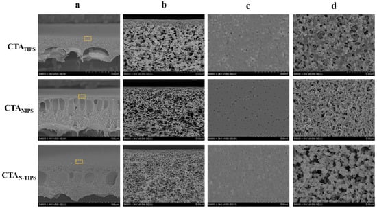
Figure 1.
FESEM images of the cross-section (a,b); the top surface (c); and the bottom surface (d) of CTA porous substrates prepared by TIPS, NIPS and N-TIPS methods. The images of line b show the magnified morphology of the regions indicated by the rectangles in the images of line a.
The NIPS process can be induced by using DI water as the cooling bath, which is miscible with DMSO2. As the CTA/DMSO2/PEG400 solution at 160 °C was immersed into DI water, the mass exchange between DMSO2 and DI water immediately took place at the surface of the liquid membrane, and a dense surface layer formed. The intruded DI water further induced the phase separation across the whole CTA/DMSO2/PEG400 solution. Finally, finger-like macropores formed inside the membrane as the typical morphology of membranes prepared by NIPS process, which were found in the cross-section of CTANIPS and CTAN-TIPS substrates (Figure 1a). The CTANIPS substrate completely eliminated the granular structure, while the CTAN-TIPS substrate still retained a part of it (Figure 1b,d). This result can be ascribed to the temperature difference between the solution and the cooling bath that determines the competitive relationship between TIPS and NIPS processes. Specifically, the CTANIPS substrate was prepared in the cooling bath at 95 °C, in which the driven force for the crystallization of CTA was dramatically weakened, and thus the TIPS process was inhibited. As the temperature of the DI water decreased to 50 °C, both TIPS and NIPS processes were induced and the CTAN-TIPS substrate was obtained. It can be seen that the sponge-like sublayer is thicker and the figure-like macropores are reduced in the CTAN-TIPS substrate compared to the CTANIPS substrate.
The surface structure of the porous substrate plays an essential role in the interfacial polymerization and the polyamide morphology. As shown in Figure 1c, the CTATIPS substrate has a granular top surface due to the crystallization of CTA on the surface. As the NIPS process was introduced, the granule size decreases and the top surfaces of the CTANIPS and CTAN-TIPS substrates become smooth. These results are further confirmed by AFM. Figure 2 shows that the CTAN-TIPS substrate has the smoothest top surface with an average roughness value as low as 4.46 nm, much lower than those of CTATIPS (17.75 nm) and CTANIPS (9.24 nm).
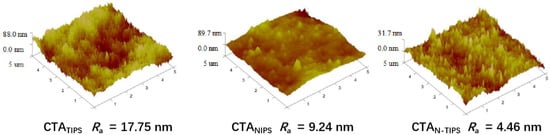
Figure 2.
AFM images of CTA porous substrates.
The surface pore size and the surface porosity of the CTA porous substrates were counted and shown in Figure 3a. It is clear that the CTAN-TIPS substrate had a surface pore size of 11.1 nm, similar to that of the CTATIPS substrate (11.7 nm). However, the surface porosity of CTAN-TIPS substrate dramatically increased, which means that the NIPS process is beneficial to the surface pore formation through the mass exchange of DMSO2 and DI water. In contrast, the CTANIPS substrate had the largest surface pore size (18.8 nm) and highest surface porosity (5.4%). On the other hand, the overall porosity of the CTAN-TIPS substrate was 71.9%, larger than that of the CTATIPS substrate (60.9%) and the CTANIPS substrate (67.7%) (Figure 3b).
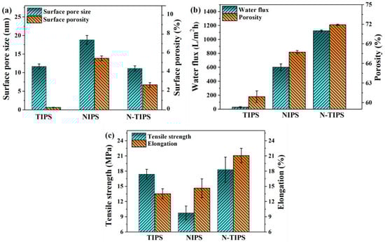
Figure 3.
(a) Surface pore size and surface porosity of CTA porous substrates; (b) water flux and overall porosity of CTA porous substrates; (c) tensile strength and elongation of CTA porous substrates.
As indicated in Figure 3b,c, the properties of CTA porous substrates were tested in terms of pure water flux, tensile strength, and elongation. The CTAN-TIPS substrate displayed the largest water flux of 1124.0 L/m2·h, which was almost two times as large as that of CTANIPS substrate (602.4) and forty times larger than that of the CTATIPS substrate (29.7). The excellent water permeability of CTAN-TIPS substrate is mainly contributed to its large overall porosity, porous top surface, and sponge-like pore structure. Figure 3c demonstrates the mechanical properties of CTA porous substrates. It is widely believed that high mechanical strength is one of the advantages of polymer membranes prepared using the TIPS method. Herein, the CTATIPS substrate showed higher tensile strength (17.4 MPa) than that of the CTANIPS substrate (9.8 MPa) due to its uniform pore structure and relatively low porosity. However, the elongation of CTATIPS substrate (13.5%) was a little lower than that of the CTANIPS substrate (14.6%), which is because the stacked granular structure may become the breaking point. In contrast, the CTAN-TIPS substrate demonstrated the best tensile strength (18.2 MPa) and elongation (21.1%), which was beneficial for both the TIPS and the NIPS process.
3.2. Surface Chemical Composition and Morphology of TFC-FO Membranes
ATR-FTIR was used to characterize the surface chemical composition of TFC-FO membrane and confirm the formation of a polyamide (PA) layer on the CTA substrate. As shown in Figure 4a, three absorption peaks at 1663 cm−1, 1610 cm−1, and 1542 cm−1 were detected, which represent the stretching vibration of -C=O (amide I), the aromatic amide bond, and the stretching band of C-N (amide II), respectively []. Moreover, the XPS spectra also indicated the formation of PA layer based on the signal of nitrogen element (Figure 4b). These results reveal that the IP reaction was conducted and a PA-selective layer was formed on all kinds of CTA porous substrates. Furthermore, the surface element content of TFC-FO membranes was further calculated by the XPS result (Table 2). According to the O/N ratio, the cross-linking degree of PA on TFCNIPS membrane is higher than those of TFCTIPS and TFCN-TIPS membranes.
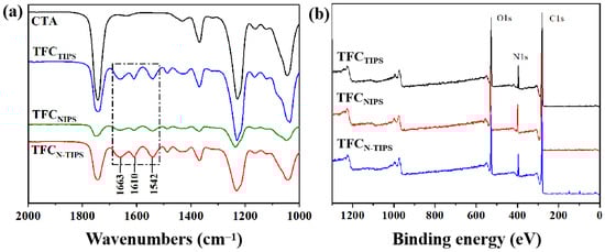
Figure 4.
(a) ATR-FTIR spectra and (b) XPS spectra of TFC-FO membranes.
Table 2.
Surface element content of TFC-FO membranes measured by XPS.
As shown in Figure 5a, all the TFC-FO membranes present a “ridge-and-valley” top surface as a typical morphology of the PA layer from interfacial polymerization. Moreover, a large leaf-like structure can be observed on TFCNIPS membrane, whereas a nodular and worm-like structure is highly obvious on TFCN-TIPS membrane. This result means more MPD exists on the CTAN-TIPS and CTANIPS substrates than on the CTATIPS substrate, which is due to the relatively large surface pore size and surface porosity of the former (Figure 6). The adsorbed MPD within the porous substrates further diffuses out, reacts with the residual acyl chlorides, and forms a thick PA film []. Correspondingly, the PA layer of TFCNIPS membrane has an average thickness of 300 nm, larger than that of TFCN-TIPS (235 nm) and TFCTIPS membranes (207 nm). The enlarged view of the cross-section reveals that the PA layers on the loose CTAN-TIPS and CTANIPS substrates have intensively nodular protuberance, and voids existed inside the whole ridge-and-valley structure (Figure 5b). In contrast to the dense PA layer of TFCTIPS membrane, the nodular protuberance and voids facilitate to increase the water transporting area and then enhance the water flux of TFC-FO membranes [,].
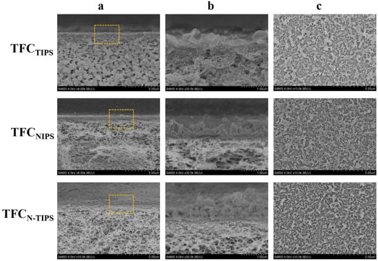
Figure 5.
SEM images illustrating the cross-section (a,b) and top surface (c) of TFC-FO membranes. The images of line b show the magnified morphology of the regions indicated by the rectangles in the images of line a.
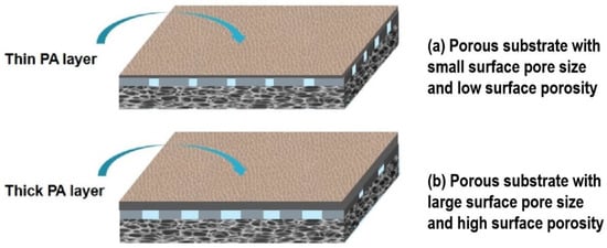
Figure 6.
Schematic of PA layer formed on different porous substrates. (a) A substrate with small surface pore size and low surface porosity prefers to form a thin PA layer; (b) a substrate with large surface pore size and high porosity prefers to form a thick PA layer.
Moreover, AFM was also conducted to detect the surface morphology and the mean roughness (Ra) of the TFC-FO membranes. As can be seen in Figure 7, the rutted and uneven surface is obvious on TFCTIPS membrane, whereas the small bulges homogenously lay on TFCNIPS membrane. This result is similar to that observed under SEM, as mentioned above. Correspondingly, the Ra values for TFCTIPS (198 nm) are much larger than those for TFCNIPS (127 nm), and TFCN-TIPS (110 nm). This result suggests that CTA porous substrates with a smooth surface and high surface porosity may lead to relatively smooth PA films.
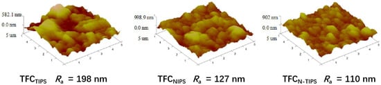
Figure 7.
AFM images of TFC-FO membranes with different CTA porous substrates.
3.3. FO Performance of TFC-FO Membranes
The FO performance of the fabricated TFC-FO membranes was evaluated in both AL-FS and AL-DS by using DI water as a feed solution and 1 M NaCl as a draw solution. As shown in Figure 8a, all the TFC-FO membranes displayed higher water fluxes in AL-DS than those in AL-FS due to the severe ICP effect in the AL-FS. Among others, TFCN-TIPS (16.84 LMH in AL-DS and 14.89 LMH in AL-FS) and TFCNIPS membranes (19.54 LMH in AL-DS and 16.94 LMH in AL-FS) presented relatively higher water fluxes than TFCTIPS membrane (10.08 LMH in AL-DS and 8.41 LMH in AL-FS). Moreover, the reverse salt flux of TFCN-TIPS membrane was much lower (4.67 gMH in AL-FS, and 10.03 gMH in AL-DS) than in TFCN-TIPS and TFCTIPS membranes (Figure 8b). Therefore, TFCN-TIPS membrane demonstrates the smallest specific salt flux (JS/JW ratio), indicating the best selectivity for water molecules (Figure 8c).
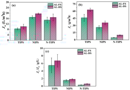
Figure 8.
(a) Water flux; (b) reverse salt flux; and (c) specific salt flux of TFC-FO membranes at AL-DS and AL-FS modes. The draw solution and feed solution are 1.0 M NaCl and DI water, respectively. The cross-flow velocity is 20 L/h.
The performance of TFC-FO membranes can be connected to the morphology and the surface composition of the PA layer, including the surface structure, the thickness, and the cross-linking degree [,]. Compared with TFCTIPS membrane, the higher water flux for TFCN-TIPS and TFCNIPS membranes can be attributed to their intensive water-transporting area from the nodular protuberance and voids inside the PA layer, although their PA layers are thicker (Figure 5). On the other hand, the severe reverse salt flux of TFCTIPS membrane may be ascribed to the low cross-linking degree of the PA layer. Additionally, the water flux of TFC-FO membrane is connected to the ICP effect of CTA porous substrate []. Table 3 lists the intrinsic transport parameters of TFC-FO membrane, including the pure water permeability coefficient (A), salt permeability coefficient (B), salt rejection (Rs), and structural parameters (S). The TFCN-TIPS and TFCNIPS membranes have much smaller S values than TFCTIPS membrane, which indicates a relatively low ICP effect in the former. This result can be contributed to the high porosity and low pore tortuosity of the CTAN-TIPS and CTANIPS substrates, which can be indicated by the small τ values. The pure water permeability of the FO membrane was measured in a RO mode at 5 bar, using the DI water as the recycle solution. The A values of TFCNIPS (1.03 L/m2·h·bar) and TFCN-TIPS (0.90 L/m2·h·bar) membranes were 50~60% higher than that of TFCTIPS (0.61 L/m2·h·bar) membrane. Meanwhile, the TFCN-TIPS membrane demonstrated the highest NaCl rejection (92.6%) and smallest B/A value (0.39 bar), which reveals that the TFCN-TIPS membrane has excellent selectivity. In summary, the TFCN-TIPS membrane showed the best overall performance compared with the TFCTIPS and TFCNIPS membrane.
Table 3.
The intrinsic transport parameters of TFC-FO membranes.
4. Conclusions
A novel thin-film composite forward osmosis (TFC-FO) membrane was fabricated using a cellulose triacetate (CTA) porous substrate prepared via a nonsolvent, thermally induced phase separation (N-TIPS) process. It was found that the CTAN-TIPS substrate has a smooth surface and a cross-section combining interconnected pores and finger-like macropores, which endow the substrate with high water flux and good mechanical properties. Moreover, the corresponding TFC-FO membrane supported by CTAN-TIPS substrate presented the best overall performance compared with those membranes supported by CTA substrates via a non-solvent induced-phase separation or thermally induced phase separation process. The TFC-FON-TIPS membrane not only displayed both high water permeability and selectivity, but also showed a low internal concentration polarization effect.
Author Contributions
Conceptualization, Q.-Y.W.; methodology, J.-C.H., and X.-Y.X.; formal analysis, X.-Y.X.; investigation, J.-C.H.; data curation, X.-Y.X.; writing—original draft preparation, X.-Y.X.; writing—review and editing, J.-C.H., J.W. and Q.-Y.W. All authors have read and agreed to the published version of the manuscript.
Funding
This research is funded by the Guangdong Basic and Applied Basic Research Foundation (2022A1515010021).
Institutional Review Board Statement
Not applicable.
Informed Consent Statement
Not applicable.
Data Availability Statement
Not applicable.
Conflicts of Interest
The authors declare no conflict of interest.
References
- Obotey Ezugbe, E.; Rathilal, S. Membrane Technologies in Wastewater Treatment: A Review. Membranes 2020, 10, 89. [Google Scholar] [CrossRef] [PubMed]
- Lee, A.; Elam, J.W.; Darling, S.B. Membrane materials for water purification: Design, development, and application. Environ. Sci. Water Res. Technol. 2016, 2, 17–42. [Google Scholar] [CrossRef]
- Fane, A.G.; Wang, R.; Hu, M.X. Synthetic Membranes for Water Purification: Status and Future. Angew. Chem. Int. Ed. 2015, 54, 3368–3386. [Google Scholar] [CrossRef] [PubMed]
- Xie, M.; Shon, H.K.; Gray, S.R.; Elimelech, M. Membrane-based processes for wastewater nutrient recovery: Technology, challenges, and future direction. Water Res. 2016, 89, 210–221. [Google Scholar] [CrossRef] [PubMed] [Green Version]
- Li, D.; Yan, Y.; Wang, H. Recent advances in polymer and polymer composite membranes for reverse and forward osmosis processes. Prog. Polym. Sci. 2016, 61, 104–155. [Google Scholar] [CrossRef] [Green Version]
- Yadav, S.; Saleem, H.; Ibrar, I.; Naji, O.; Hawari, A.A.; Alanezi, A.A.; Zaidi, S.J.; Altaee, A.; Zhou, J. Recent developments in forward osmosis membranes using carbon-based nanomaterials. Desalination 2020, 482, 114375. [Google Scholar] [CrossRef]
- Firouzjaei, M.D.; Seyedpour, S.F.; Aktij, S.A.; Giagnorio, M.; Bazrafshan, N.; Mollahosseini, A.; Samadi, F.; Ahmadalipour, S.; Firouzjaei, F.D.; Esfahani, M.R.; et al. Recent advances in functionalized polymer membranes for biofouling control and mitigation in forward osmosis. J. Membr. Sci. 2020, 596, 117604. [Google Scholar] [CrossRef]
- Akther, N.; Sodiq, A.; Giwa, A.; Daer, S.; Arafat, H.A.; Hasan, S.W. Recent advancements in forward osmosis desalination: A review. Chem. Eng. J. 2015, 281, 502–522. [Google Scholar] [CrossRef]
- Chekli, L.; Phuntsho, S.; Shon, H.K.; Vigneswaran, S.; Kandasamy, J.; Chanan, A. A review of draw solutes in forward osmosis process and their use in modern applications. Desalin. Water Treat. 2012, 43, 167–184. [Google Scholar] [CrossRef]
- Lu, P.; Liang, S.; Zhou, T.; Mei, X.; Zhang, Y.; Zhang, C.; Umar, A.; Wang, H.; Wang, Q. Typical Thin-Film Composite (TFC) Membranes Modified with Inorganic Nanomaterials for Forward Osmosis: A Review. Nanosci. Nanotechnol. Lett. 2016, 8, 906–916. [Google Scholar] [CrossRef]
- Alihemati, Z.; Hashemifard, S.A.; Matsuura, T.; Ismail, A.F.; Hilal, N. Current status and challenges of fabricating thin film composite forward osmosis membrane: A comprehensive roadmap. Desalination 2020, 491, 114557. [Google Scholar] [CrossRef]
- Ahmad, N.A.; Goh, P.S.; Karim, Z.A.; Ismail, A.F. Thin Film Composite Membrane for Oily Waste Water Treatment: Recent Advances and Challenges. Membranes 2018, 8, 86. [Google Scholar] [CrossRef] [Green Version]
- Zhang, X.; Tian, J.; Ren, Z.; Shi, W.; Zhang, Z.; Xu, Y.; Gao, S.; Cui, F. High performance thin-film composite (TFC) forward osmosis (FO) membrane fabricated on novel hydrophilic disulfonated poly (arylene ether sulfone) multiblock copolymer/polysulfone substrate. J. Membr. Sci. 2016, 520, 529–539. [Google Scholar] [CrossRef]
- Gray, G.T.; McCutcheon, J.R.; Elimelech, M. Internal concentration polarization in forward osmosis: Role of membrane orientation. Desalination 2006, 197, 1–8. [Google Scholar] [CrossRef]
- Ge, Q.; Ling, M.; Chung, T.-S. Draw solutions for forward osmosis processes: Developments, challenges, and prospects for the future. J. Membr. Sci. 2013, 442, 225–237. [Google Scholar] [CrossRef]
- McCutcheon, J.R.; Elimelech, M. Influence of concentrative and dilutive internal concentration polarization on flux behavior in forward osmosis. J. Membr. Sci. 2006, 284, 237–247. [Google Scholar] [CrossRef]
- Xu, J.; Tang, Y.; Gao, C. Research Progress on Optimizing the Structure of Support Layers in Forward Osmosis Membrane. Prog. Chem. 2015, 27, 1025–1032. [Google Scholar]
- Gao, Y.; Wang, Y.-N.; Li, W.; Tang, C.Y. Characterization of internal and external concentration polarizations during forward osmosis processes. Desalination 2014, 338, 65–73. [Google Scholar] [CrossRef]
- Yabuno, Y.; Mihara, K.; Miyagawa, N.; Komatsu, K.; Nakagawa, K.; Shintani, T.; Matsuyama, H.; Yoshioka, T. Preparation of polyamide—PVDF composite hollow fiber membranes with well-developed interconnected bicontinuous structure using high-temperature rapid NIPS for forward osmosis. J. Membr. Sci. 2020, 612, 118468. [Google Scholar] [CrossRef]
- Zuo, Y.C.; Chi, X.Y.; Xu, Z.L.; Guo, X.J. Morphological controlling of CTA forward osmosis membrane using different solvent-nonsolvent compositions in first coagulation bath. J. Polym. Res. 2017, 24, 156. [Google Scholar] [CrossRef]
- Yabuno, Y.; Mihara, K.; Komatsu, K.; Shimamura, S.; Nakagawa, K.; Shintani, T.; Matsuyama, H.; Yoshioka, T. Preparation of polyamide thin-film composite membranes using hydrophilic hollow fiber PVDF via the TIPS process modified by PVA diffusion. Ind. Eng. Chem. Res. 2019, 58, 21691–21699. [Google Scholar] [CrossRef]
- Wu, Q.-Y.; Xing, X.-Y.; Yu, Y.; Gu, L.; Xu, Z.-K. Novel thin film composite membranes supported by cellulose triacetate porous substrates for high-performance forward osmosis. Polymer 2018, 153, 150–160. [Google Scholar] [CrossRef]
- Matsuyama, H.; Takida, Y.; Maki, T.; Teramoto, M. Preparation of porous membrane by combined use of thermally induced phase separation and immersion precipitation. Polymer 2002, 43, 5243–5248. [Google Scholar] [CrossRef]
- Yang, L.; Wang, Z.; Zhang, J.; Song, P.; Liu, L. TIPS-co-NIPS method to prepare PES substrate with enhanced permeability for TFC-FO membrane. J. Taiwan Inst. Chem. Eng. 2017, 80, 137–148. [Google Scholar] [CrossRef]
- Jung, J.T.; Wang, H.H.; Kim, J.F.; Lee, J.; Kim, J.S.; Drioli, E.; Lee, Y.M. Tailoring nonsolvent-thermally induced phase separation (N-TIPS) effect using triple spinneret to fabricate high performance PVDF hollow fiber membranes. J. Membr. Sci. 2018, 559, 117–126. [Google Scholar] [CrossRef]
- Jung, J.T.; Kim, J.F.; Wang, H.H.; Di Nicolo, E.; Drioli, E.; Lee, Y.M. Understanding the non-solvent induced phase separation (NIPS) effect during the fabrication of microporous PVDF membranes via thermally induced phase separation (TIPS). J. Membr. Sci. 2016, 514, 250–263. [Google Scholar] [CrossRef]
- Nakao, T.; Milura, Y.; Furuichi, K.; Yasukawa, M. Cellulose Triacetate (CTA) Hollow-Fiber (HF) Membranes for Sustainable Seawater Desalination: A Review. Membranes 2021, 11, 183. [Google Scholar] [CrossRef]
- Jamil, T.S.; Nasr, R.A.; Abbas, H.A.; Ragab, T.M.; Xabela, S.; Moutloali, R. Low-Cost High Performance Polyamide Thin Film Composite (Cellulose Triacetate/Graphene Oxide) Membranes for Forward Osmosis Desalination from Palm Fronds. Membranes 2022, 12, 6. [Google Scholar] [CrossRef]
- Thi Phuong Nga, N.; Yun, E.-T.; Kim, I.-C.; Kwon, Y.-N. Preparation of cellulose triacetate/cellulose acetate (CTA/CA)-based membranes for forward osmosis. J. Membr. Sci. 2013, 433, 49–59. [Google Scholar]
- Yu, Y.; Wu, Q.-Y.; Liang, H.-Q.; Gu, L.; Xu, Z.-K. Preparation and characterization of cellulose triacetate membranes via thermally induced phase separation. J. Appl. Polym. Sci. 2017, 134, 44454. [Google Scholar] [CrossRef]
- Xing, X.-Y.; Gu, L.; Jin, Y.; Sun, R.; Xie, M.-Y.; Wu, Q.-Y. Fabrication and characterization of cellulose triacetate porous membranes by combined nonsolvent-thermally induced phase separation. Cellulose 2019, 26, 3747–3762. [Google Scholar] [CrossRef]
- Wu, Q.-Y.; Wan, L.-S.; Xu, Z.-K. Structure and performance of polyacrylonitrile membranes prepared via thermally induced phase separation. J. Membr. Sci. 2012, 409, 355–364. [Google Scholar] [CrossRef]
- Huang, L.; McCutcheon, J.R. Impact of support layer pore size on performance of thin film composite membranes for forward osmosis. J. Membr. Sci. 2015, 483, 25–33. [Google Scholar] [CrossRef]
- Ritt, C.L.; Stassin, T.; Davenport, D.M.; DuChanois, R.M.; Nulens, I.; Yang, Z.; Ben-Zvi, A.; Segev-Mark, N.; Elimelech, M.; Tang, C.Y.; et al. The open membrane database: Synthesis-structure-performance relationships of reverse osmosis membranes. J. Membr. Sci. 2022, 641, 119927. [Google Scholar] [CrossRef]
- Li, X.; Wang, Z.; Han, X.; Liu, Y.; Wang, C.; Yan, F.; Wang, J. Regulating the interfacial polymerization process toward high-performance polyamide thin-film composite reverse osmosis and nonfiltration membranes: A review. J. Membr. Sci. 2021, 640, 119765. [Google Scholar] [CrossRef]
- Zhou, Z.; Hu, Y.; Boo, C.; Liu, Z.; Li, J.; Deng, L.; An, X. High-Performance Thin-Film Composite Membrane with an Ultrathin Spray-Coated Carbon Nanotube Interlayer. Environ. Sci. Technol. Lett. 2018, 5, 243–248. [Google Scholar] [CrossRef]
- Khorshidi, B.; Bhinder, A.; Thundat, T.; Pernitsky, D.; Sadrzadeh, M. Developing high throughput thin film composite polyamide membranes for forward osmosis treatment of SAGD produced water. J. Membr. Sci. 2016, 511, 29–39. [Google Scholar] [CrossRef]
Publisher’s Note: MDPI stays neutral with regard to jurisdictional claims in published maps and institutional affiliations. |
© 2022 by the authors. Licensee MDPI, Basel, Switzerland. This article is an open access article distributed under the terms and conditions of the Creative Commons Attribution (CC BY) license (https://creativecommons.org/licenses/by/4.0/).