1. Introduction
The ammonia decomposition reaction has a significant endothermic effect. The active temperature of the reaction is about 700 K, which is very suitable for a trough solar collector. Therefore, ammonia is an excellent medium for solar thermal chemical energy storage. At the same time, ammonia has great potential for producing hydrogen without any carbon emissions. So, using ammonia for solar energy storage can produce and sell hydrogen in the case of excess heat, realizing solar hydrogen production.
As for the research in the energy storage field, in 1992, Lovegrove et al. [
1,
2,
3,
4,
5] of the Australian National University (ANU) solar group conducted experiments with an electrically heated ammonia reactor. He showed that the ammonia reactor could absorb up to 2 kW of heat. After that, Luzzi et al. [
6,
7] analyzed the performance of the ammonia decomposition reactor heated by a butterfly solar concentrator. He found that the peak endothermic power can reach 2.5 kW, and the solar energy absorption rate can reach 58%. In 1999, the ANU solar group built the first solar thermal storage system with ammonia as the circulating medium using a 20 m² butterfly collector, achieving a continuous output of 1 kW of power for 24 h [
3,
7,
8,
9,
10].
The use of membrane reactors in the ammonia decomposition process can improve system performance. The existing research on ammonia decomposition membrane reactors mainly focuses on its influence on thermodynamic equilibrium. Wang et al. [
11] applied ammonia decomposition membrane reactors to reduce the temperature of complete ammonia decomposition by about 200 °C under commercial Ni-based catalysts. Rizzuto et al. [
12] conducted palladium membrane reactor experiments using the Ru catalyst and found that the ammonia conversion rate was the most stable when the temperature was 450 °C. The ammonia conversion rate was over 99.4% under all experimental conditions. Itoh et al. [
13,
14] found that the ammonia conversion of the membrane reactor was 15% higher than that of the conventional reactor at 723 K through theoretical modeling and experiments, and the hydrogen recovery was 60%. Cechetto et al. [
15] achieved complete ammonia decomposition at 425 °C using a ruthenium-based catalyst and a palladium membrane and recovered more than 86% of hydrogen.
There is more engineering significance to analyzing and optimizing the ammonia decomposition membrane reactor. Abashar et al. [
16,
17] found an optimized ammonia feed point distribution of the membrane reactor using modeling, which can increase the reaction rate by 17.45% and reduce the reactor length by 75%. Wang et al. [
18] modeled and studied one thermostatic ammonia decomposition membrane reactor heated by solar and found that the energy conversion rate can reach 40.08%. The energy conversion rate is defined as the ratio of incremental chemical energy to solar energy input. Xie et al. [
19,
20] established the solar endothermic system model for ammonia decomposition based on membrane reactors. The effects of factors such as the reactor radius, ammonia flow rate, light intensity and permeation zone pressure on system performance were analyzed.
In the existing research on the solar-heated ammonia decomposition membrane reactor, Wang et al. [
18] used a thermostatic reactor to decompose ammonia and then converted the energy consumption into solar energy. This is not enough to meet the boundary conditions of practical engineering. The membrane reactor model of Xie et al. [
19,
20] utilizes the vacuum insulation layer outside the reactor for hydrogen permeation. This will result in a higher heat loss and thus affect system performance. To meet the demand of the engineer boundary conditions, reduce the heat loss and analyze the effect of reactor parameters on performance, this paper use finite-time thermodynamics [
21,
22,
23,
24] to establish an ammonia decomposition membrane reactor model with the outermost vacuum insulation layer, the middle annular reaction zone and the innermost layer a nitrogen-sweeping permeation zone. The effects of the ammonia flow rate, nitrogen flow rate, light intensity and radius of the permeation zone on the heat absorption rate (HAR), ammonia conversion rate (ACR), hydrogen production rate (HPR), entropy generation rate (EGR) and energy conversion rate (ECR) of the reactor are analyzed.
2. Physical Model
Figure 1 is the model schematic of a solar heating ammonia decomposition membrane reactor. Sunlight is directed onto the LS-3 concentrating collector [
19] and then converges on the reactor, heating and raising the gas temperature in the reaction zone to drive the ammonia decomposition reaction.
2.1. Solar Collector Model
The collector converges sunlight to the outer wall of the membrane reactor to provide energy for the ammonia decomposition reaction.
Table 1 shows the basic geometric and optical parameters of the LS-3 type solar collector.
According to the surface light intensity on the ground, the solar power density absorbed by the reactor can be converted as [
19,
20]:
where
Psun is the average light intensity on the ground, in W/m
2;
Ptube is the power density of absorbed solar energy, in W/m.
2.2. Reaction Kinetic Model
The reaction zone is filled with a commercially available Ru/Al
2O
3 catalyst, and the rate equation for the ammonia decomposition obeys the Temkin–Pyzhev mechanism [
25,
26,
27]:
where
pi is the partial pressure of each component in the reaction zone, in bar, and the different subscript
i means a different component (A is ammonia, N is nitrogen and H is hydrogen);
Keq is the equilibrium constant;
Kapp is the speed constant of the ammonia decomposition reaction;
RA is the reaction rate of ammonia decomposition;
β is a constant which is related to the catalyst surface state.
Kapp in Equation (2) is calculated by:
where
k0 is the pre-exponential factor, and
Eapp is the activation energy of the ammonia decomposition reaction of the catalyst.
In the study by Prasad et al. [
27], they prepared an Ru/Al
2O
3 catalyst (with 4% Ru). To determine the reaction kinetic parameters, they used a flow controller to control the flow rates of ammonia, hydrogen, nitrogen and helium input into the reactor, measured the temperature distribution of the reactor using thermocouples and then used the experimentally measured data to refine the model parameters. Finally, they obtained the parameter values in Equations (2) and (3):
β = 0.27,
k0 = 6 × 10
8 s
−1 and
Eapp = 117 kJ/mol.
2.3. Membrane Reactor Model
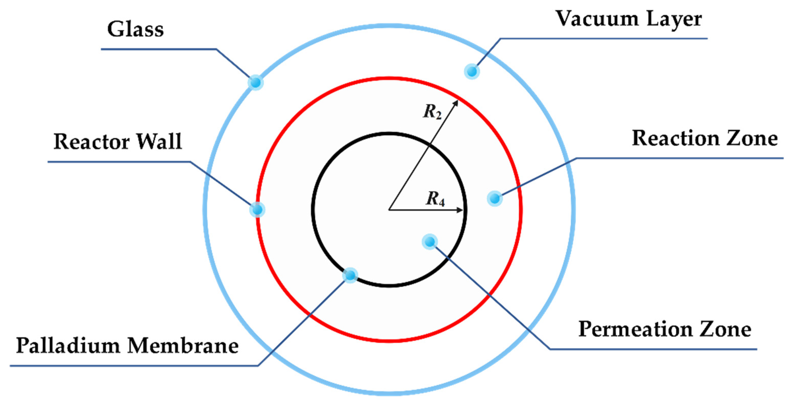
The cutaway view of the ammonia decomposition membrane reactor is shown in
Figure 2. The reactor is divided into three areas by a three-layer structure. The outermost layer is the glass layer, which allows light to pass through; the middle layer is the outer wall of the reactor, which is coated with a special coating to improve the absorption rate of solar radiation and reduce the emissivity; the innermost layer is a palladium membrane with support structures, allowing hydrogen to pass through from the reaction zone to the permeation zone. The outermost annular area is a vacuum area, which can effectively weaken the convective heat loss of the reactor outer wall; the middle annular area is a reaction area, with the Ru/Al
2O
3 catalyst added, and the ammonia decomposition reaction is also carried out here; the innermost circular area is the permeation zone, where the hydrogen permeating from the reaction zone is swept by nitrogen in the co-current mode.
The basic parameters of the membrane reactor model are shown in
Table 2.
The reactor model can be described by mass conservation, momentum conservation and energy conservation.
2.3.1. Mass Conservation Equation
The change in the hydrogen flow rate can represent the mass conservation equation in the reaction zone well:
where
FH is the hydrogen flow rate in the reaction area, in mol/s;
SRA is the area of the reaction zone;
JH is the permeability of hydrogen.
The hydrogen in the permeation zone comes entirely from permeation, so its flow rate change is:
The hydrogen permeability of the palladium membrane is [
18,
28]:
where
pH and
pH,P are the hydrogen partial pressure in the reaction zone and the permeation zone, respectively, in Pa;
TM is the temperature of the membrane, which is calculated by the temperature of the reaction zone and the permeation zone and the thermal resistance on both sides of the membrane;
n takes 0.62 [
18,
28].
2.3.2. Momentum Conservation Equation
Momentum conservation is described by the pressure drop during flowing. In trial calculation, when the flow rate rises from 0.3 mol/s to 0.6 mol/s, the
Re number in the reaction zone ranges from 15,000 to 31,000, so the pressure drop in the reaction zone can be described by the Hicks equation [
29,
30,
31]:
where
ReR is the
Re number of the gas flow in the reaction zone;
cR is the flow rate, in m/s;
ρR is the average density of the gas in the reaction zone, in kg/m
3.
The pressure drop in the permeation zone is calculated by Darcy’s formula [
32]:
2.3.3. Energy Conservation Equation
Local temperature change can be used to describe energy conservation. In the reaction zone:
where
HR is the heat absorbed by the ammonia decomposition reaction;
HE is the heat loss rate caused by the thermal radiation of the outer wall;
HT is the heat transferred from the reaction zone to the permeation zone;
HH is the energy loss caused by the permeation of hydrogen.
Since the energy in the permeation zone comes from reaction zone, the temperature change in the permeation zone is:
2.4. Performance Indicators
The conversion rate is an important performance indicator of the reactor which can measure the progress of the reaction. The ammonia conversion rate (ACR) is defined as:
where
FA,out and
FA,in are the outlet and inlet ammonia flow rates of the reaction zone, in mol/s.
If the reactor is used for solar hydrogen production, the hydrogen production rate (HPR) will be its core performance indicator:
where
FH,out and
FH,P,out are the outlet hydrogen molar flow rate in both the reaction and permeation zones, in mol/s.
The entropy generation rate (EGR) is an important performance indicator measuring the reversibility of a system or process:
where
SR is the entropy generation rate caused by chemical reaction;
SH,TR is the entropy generation rate in the process of heat transfer from the outer wall to the reaction gas;
SH,RP is the entropy generation rate of heat transfer from the reaction zone to the permeation zone;
SF is the entropy generation due to the flow pressure drop in the reaction zone;
SF,PA is the flow entropy generation in the permeate zone.
The local entropy generation rate of each process is [
33,
34,
35,
36,
37]:
where
SRA and
SPA are the areas of the reaction and permeation zones, in m
2;
cRA and
cPA are the gas flow velocities in the reaction and permeation zones, in m/s;
RA is the reaction rate of ammonia decomposition; Δ
G is the Gibbs free energy of the reaction;
qTR and
qRP are the heat fluxes transferred from the reactor wall to the reaction gas and from the reaction zone to the permeation zone, respectively.
Therefore, the entropy generation rate of each process can be obtained by integrating the above local entropy generation rate over the length of the reactor.
Used in the field of solar energy storage, the heat absorption rate (HAR) is the core performance index of the heat storage reactor. It is the total amount of solar energy absorbed by the reactor:
where
Ptube is the power density of absorbed solar energy;
HE is the heat loss due to radiation.
As a chemical energy storage system, the energy conversion rate (ECR) of the endothermic reactor is also an important core indicator, which means that the energy converted into chemical energy accounts for a proportion of the total solar energy received:
3. Numerical Example
3.1. Performance Simulation of the Reference Reactor
According to the “Thermal Design Regulations for Civil Buildings” (JGJ24-86), the average ground solar radiation intensity is about 700 W/m
2. So, when the light intensity is 700 W/m
2, under the parameters in
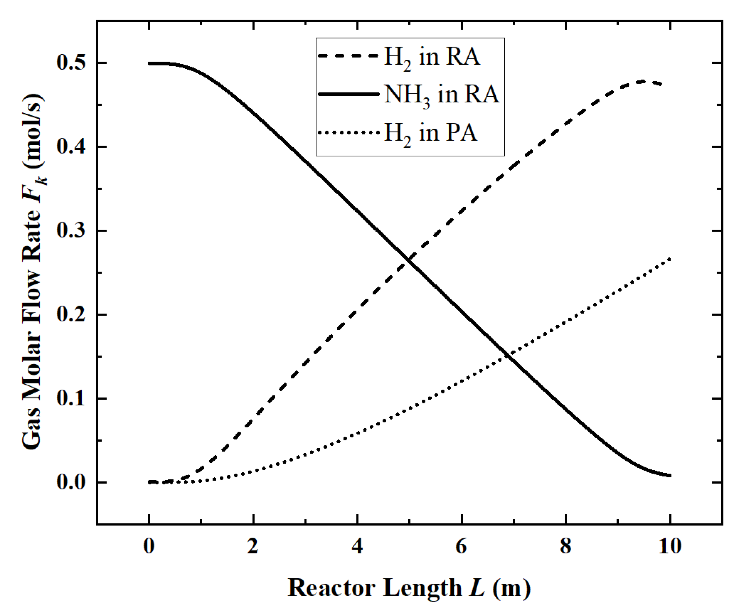
Table 2, the local flow rate of each component (
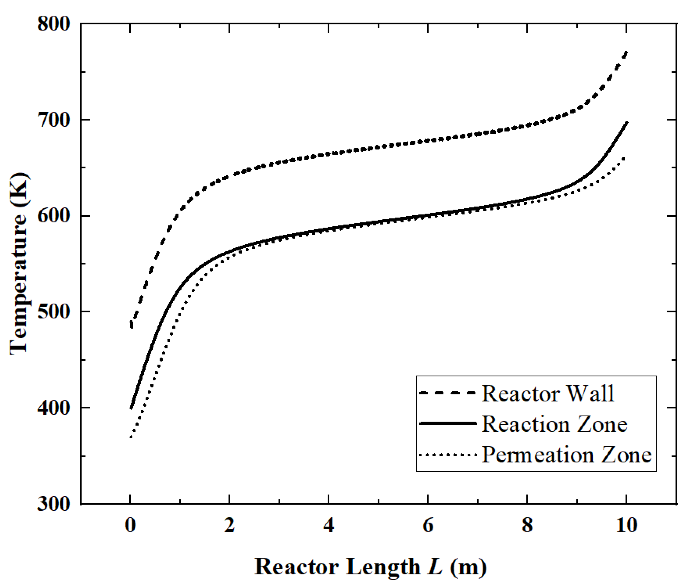
Figure 3) and the temperature distribution (
Figure 4) along the length of the reactor are obtained.
In
Figure 3, ammonia decomposition reaction begins to occur within 1 m of the inlet section of the reactor. Because of the need to accumulate the partial pressure, obvious hydrogen permeation occurs only after 2 m. At the end of the reactor, ammonia is nearly completely decomposed, and the reaction rate is significantly reduced. At the same time, due to the existence of the permeation phenomenon, the partial pressure of hydrogen in the reaction zone began to decrease.
Corresponding to
Figure 3, in
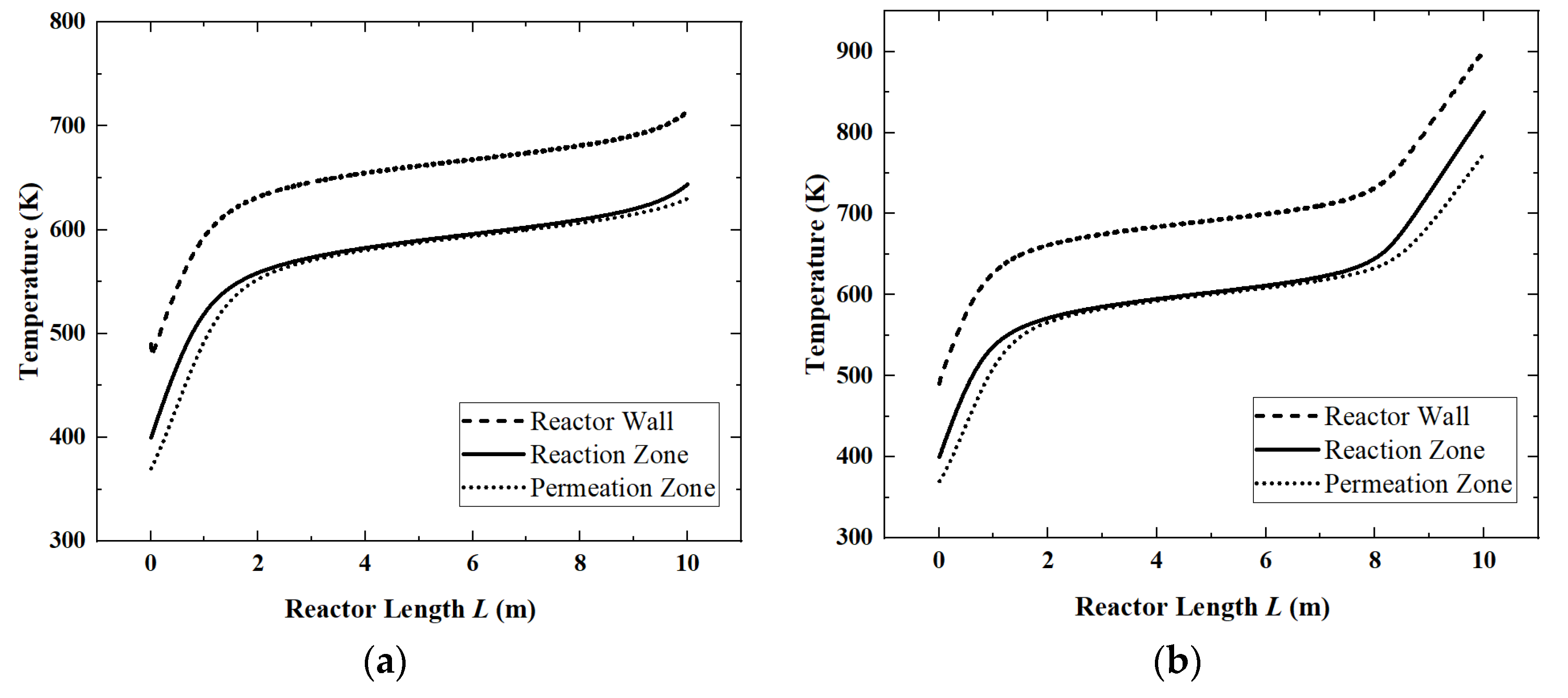
Figure 4, since the ammonia decomposition reaction is not active in the first 1 m, the absorbed solar energy is mainly used to increase the temperature of the whole system. In the middle part of the reactor, the overall temperature tends to be stable because the ammonia decomposition reaction absorbs the solar energy. The temperature difference between the reaction zone and the permeation zone is small. However, at the end of the reactor, as the ammonia is nearly completely decomposed, the reaction rate drops and the temperature rise occurs again.
For the reference reactor, the ACR is 98.4%, the HPR is 0.74 mol/s, the EGR is 48.61 W/K, the HAR is 32.2 kW and the ECR is 61.6%.
3.2. Effect of Light Intensity on Reactor Performance
Solar energy is the energy source for the ammonia decomposition reaction, and the level of energy supply is a key external factor that directly determines the performance of the reactor. Therefore, under the premise of keeping other parameters as reference values, the changes in the performance indicators of the reactor as the surface light intensity increases from 500 W/m
2 to 800 W/m
2 are analyzed.
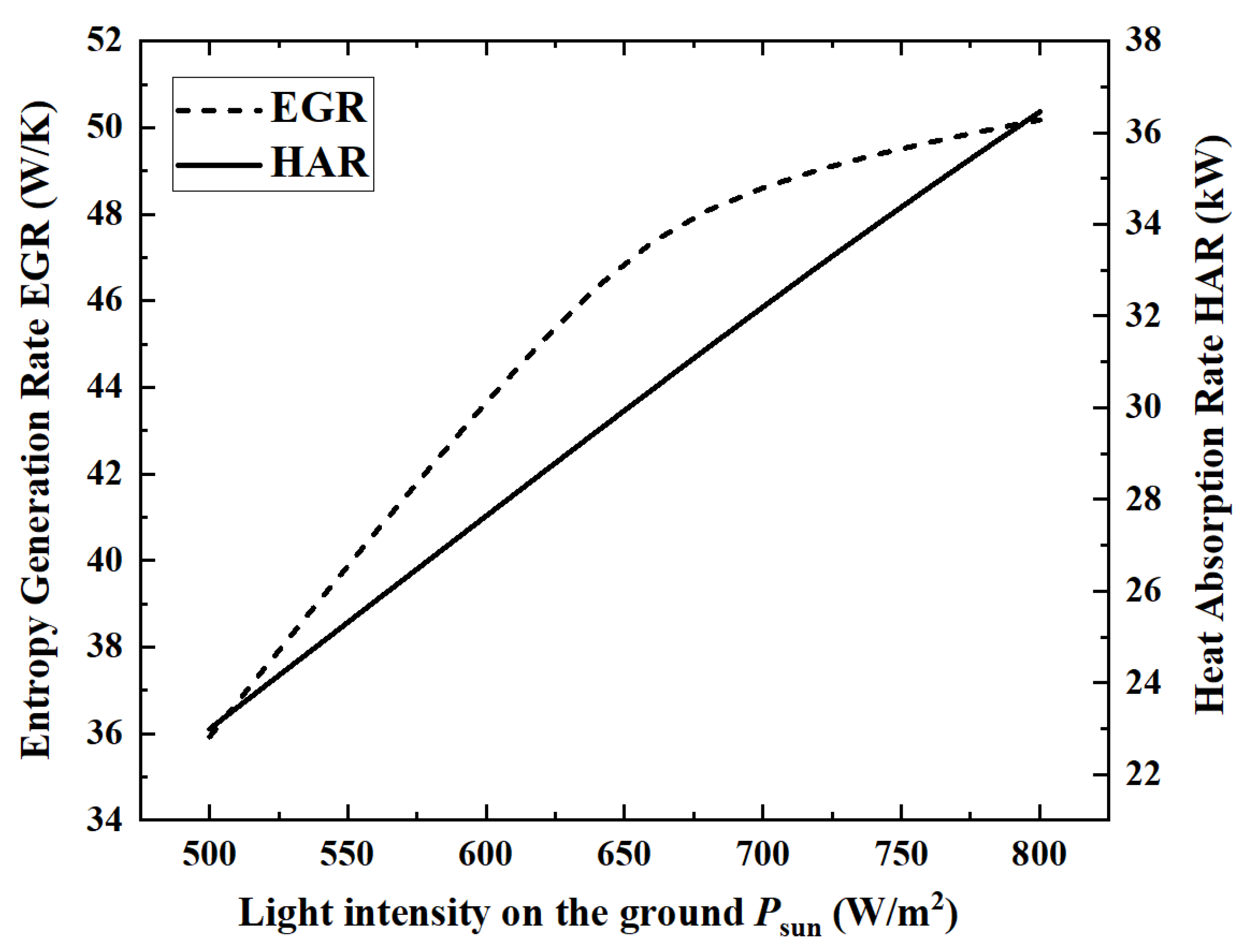
Figure 5 and
Figure 6 show the changes of the five performance indicators of ACR, HPR, EGR, HAR and ECR.
When the light intensity is 800 W/m2, the maximum HAR is 36.45 kW. From the numerical change in performance indicators, with the increase in light intensity, ACR, EGR, HAR and HPR increase by 36.2%, 39.6%, 58.5% and 36.2%, respectively, while ECR decreases by 14.2%.
From the perspective of the changing laws of the curves, in
Figure 5 and
Figure 6, except for the continuous growth of HAR, the curves of the remaining four indicators show an inflection point when the light intensity is about 650 W/m
2. This is because, under the premise that the ammonia gas flow rate remains unchanged, the ammonia gas is almost completely decomposed when the light intensity reaches above 650 W/m
2. Therefore, when the light intensity is above 650 W/m
2, ACR and HPR remain basically unchanged, and ECR begins to decrease.
In
Figure 7, when the light intensity is 650 W/m
2, ammonia happens to be completely decomposed. So, the reactor temperatures keep stable after 2 m. When the light intensity is 800 W/m
2, the reactor temperatures start to rise rapidly after 8 m, because, in this case, ammonia decomposes completely at 8 m, and after that, it can only rely on the increase in temperature to absorb solar heat.
When the light intensity is above 650 W/m2, the ammonia decomposition reaction has completed. So, all the solar energy needs to be absorbed by the temperature increase, which leads to an increase in heat transfer entropy generation. The entropy generation of the chemical reaction is close to zero at this time, so the EGR curve still rises, but the rising speed is much slower.
3.3. Effect of the Ammonia Flow Rate on Reactor Performance
As the working medium for energy storage or hydrogen production, the flow rate of ammonia is the most important operating parameter of the reactor and also has a decisive influence on the performance of the reactor. On the premise that the light intensity is 700 W/m
2 and other parameters are taken as reference values, the changes of each performance index as the ammonia flow rate increases from 0.3 mol/s to 0.6 mol/s are analyzed.
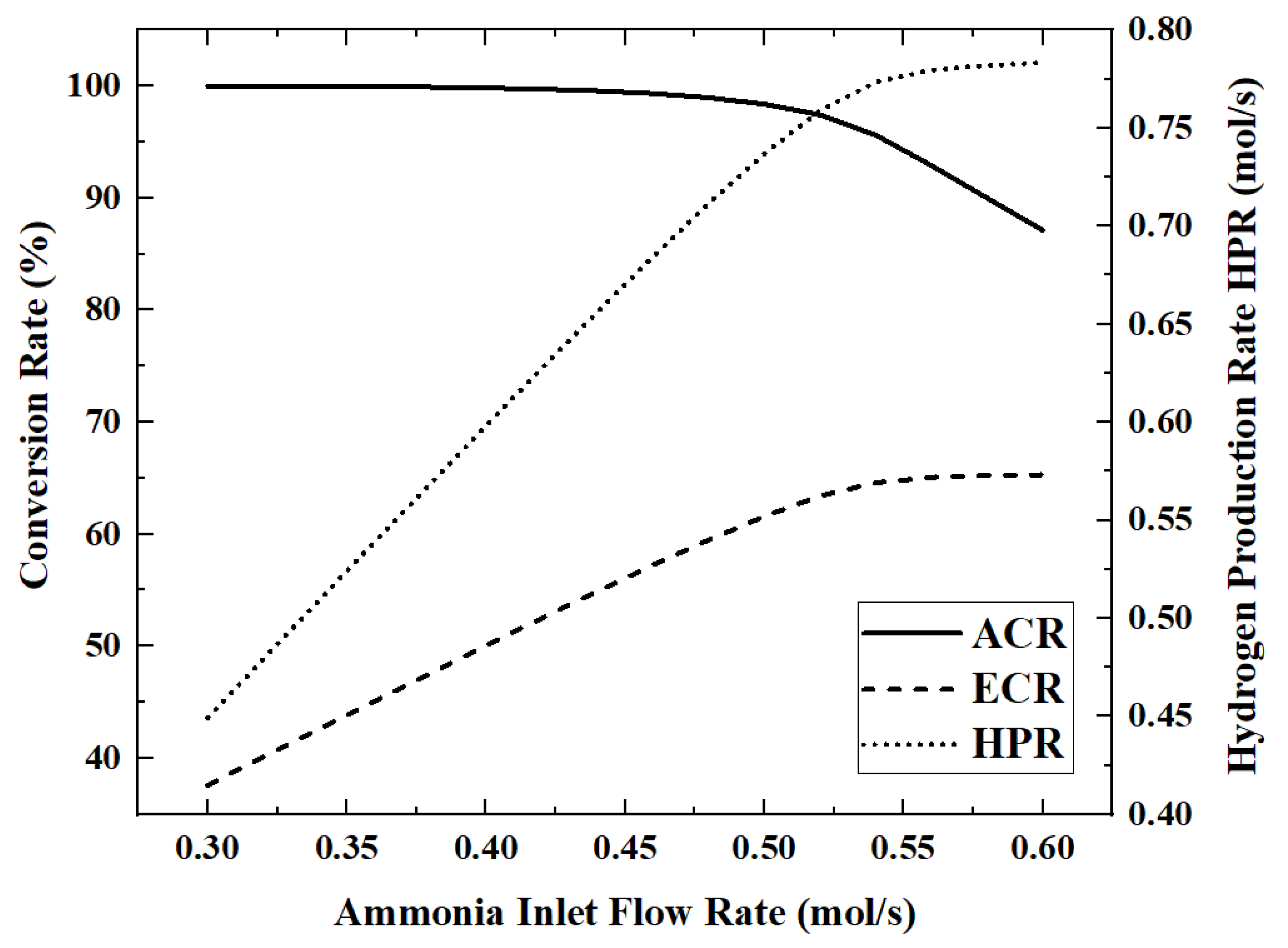
Figure 8 and
Figure 9 show the variation of five performance indicators with the increasing ammonia flow rate.
When the ammonia flow rate is 0.6 mol/s, the maximum HAR is 32.39 kW. As the ammonia flow rate increases from 0.3 mol/s to 0.6 mol/s, the ECR, EGR, HAR and HPR increase by 73.6%, 71.7%, 15.6% and 74.3%, respectively, while ACR decreases by 12.9% during this process.
In
Figure 8, ammonia is completely decomposed when the flow rate is below 0.45 mol/s, while the ACR began to decrease gradually with the increase in the ammonia flow rate. In
Figure 8 and
Figure 9, the curves of HPR, EGR and ECR all show inflection points when the ammonia flow rate is about 0.53 mol/s, rapidly changing from a linear increase to almost constant. This shows that the upper limit of HPR that can be provided by the light intensity of 700 W/m
2 is about 0.78 mol/s. ECR is also stable when HPR is stable. EGR still has a slight upward trend after HPR stabilizes, because larger flow rates lead to higher flow entropy generation. In
Figure 9, HAR gradually increases with the increase in the ammonia flow rate, but the growth rate becomes slower and slower.
3.4. Effect of the Membrane Radius on Reactor Performance
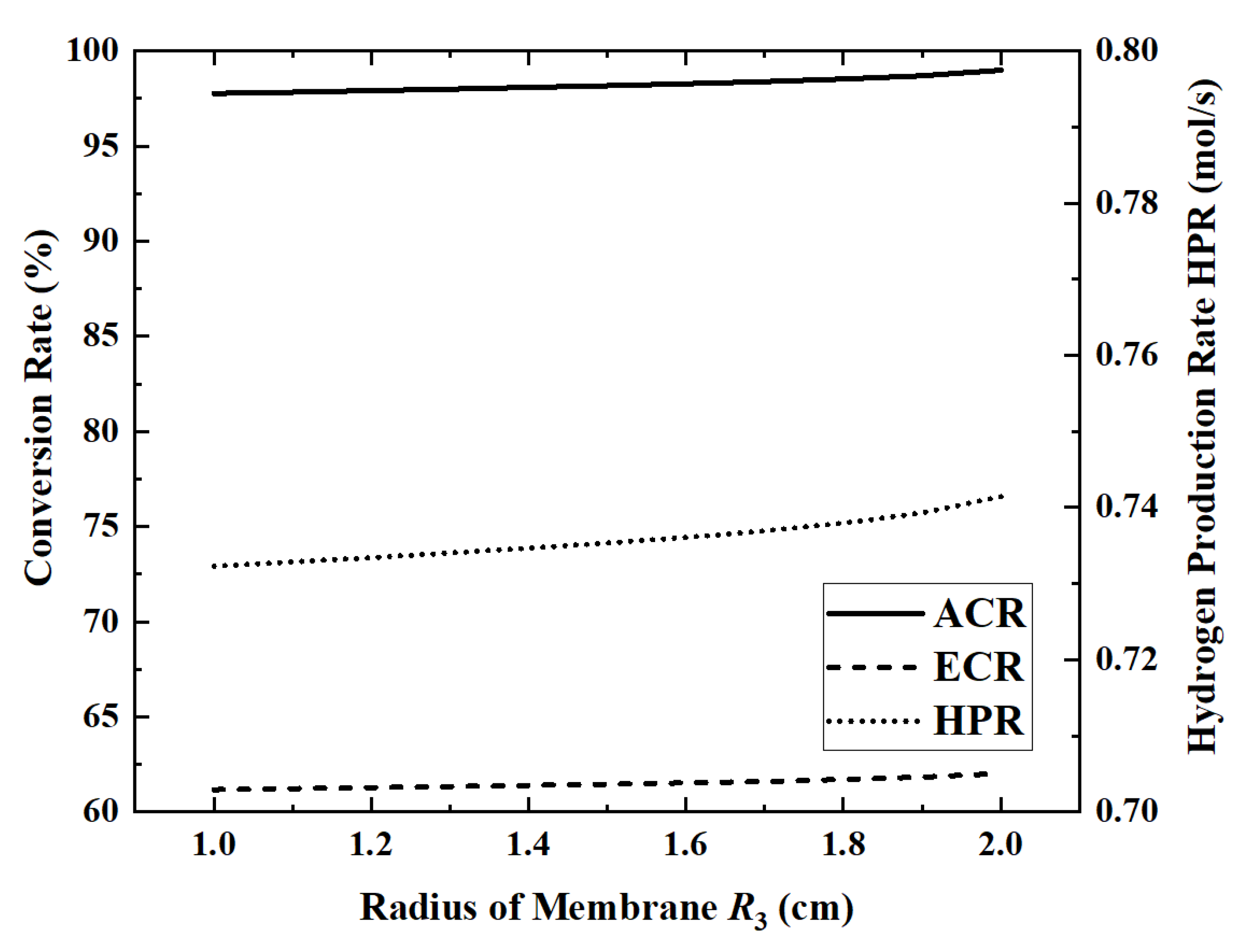
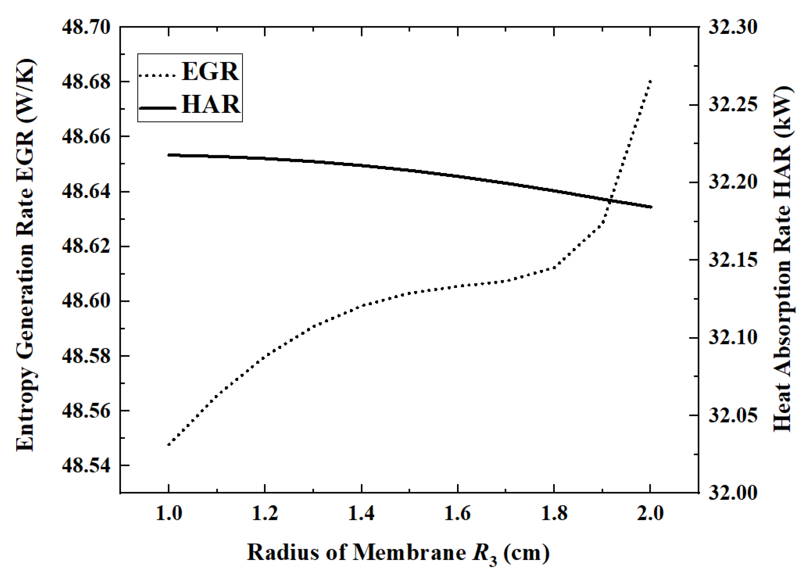
The radius of the outer wall of the reactor is determined according to the diameter of the heat absorption pipe of the LS-3 type heat collector, but there is no relevant design reference for the radius of the permeable membrane of the inner pipe. Therefore, under the condition that other parameters take reference values,
Figure 10 and
Figure 11 show the changes in performance indicators as the radius of the permeable membrane increases from 1 cm to 2 cm.
When the membrane radius is 1 cm, the maximum HAR is 32.22 kW. When the permeable membrane radius is increased from 1 cm to 2 cm, ACR, ECR, EGR and HPR increase by 1.3%, 1.4%, 0.27% and 1.3%, respectively, while HAR decreases by 0.1%. Except for EGR, all other indicators change slowly with the increase in the radius. The EGR increases slower and slower in the first part and then increases rapidly when the radius exceeds 1.7 cm. In the first half of the curve, EGR increases slowly with increasing ammonia conversion. However, once the radius exceeds 1.7 cm, the area of the reaction zone will be too low, resulting in a significant increase in flow entropy generation. When the radius increases from 1.5 cm to 1.7 cm, the flow entropy generation increases by 26.9%, while, when the radius increases from 1.7 cm to 1.9 cm, it increases by 42.4%.
3.5. Effect of the Nitrogen (Sweeping Gas) Flow Rate on Reactor Performance
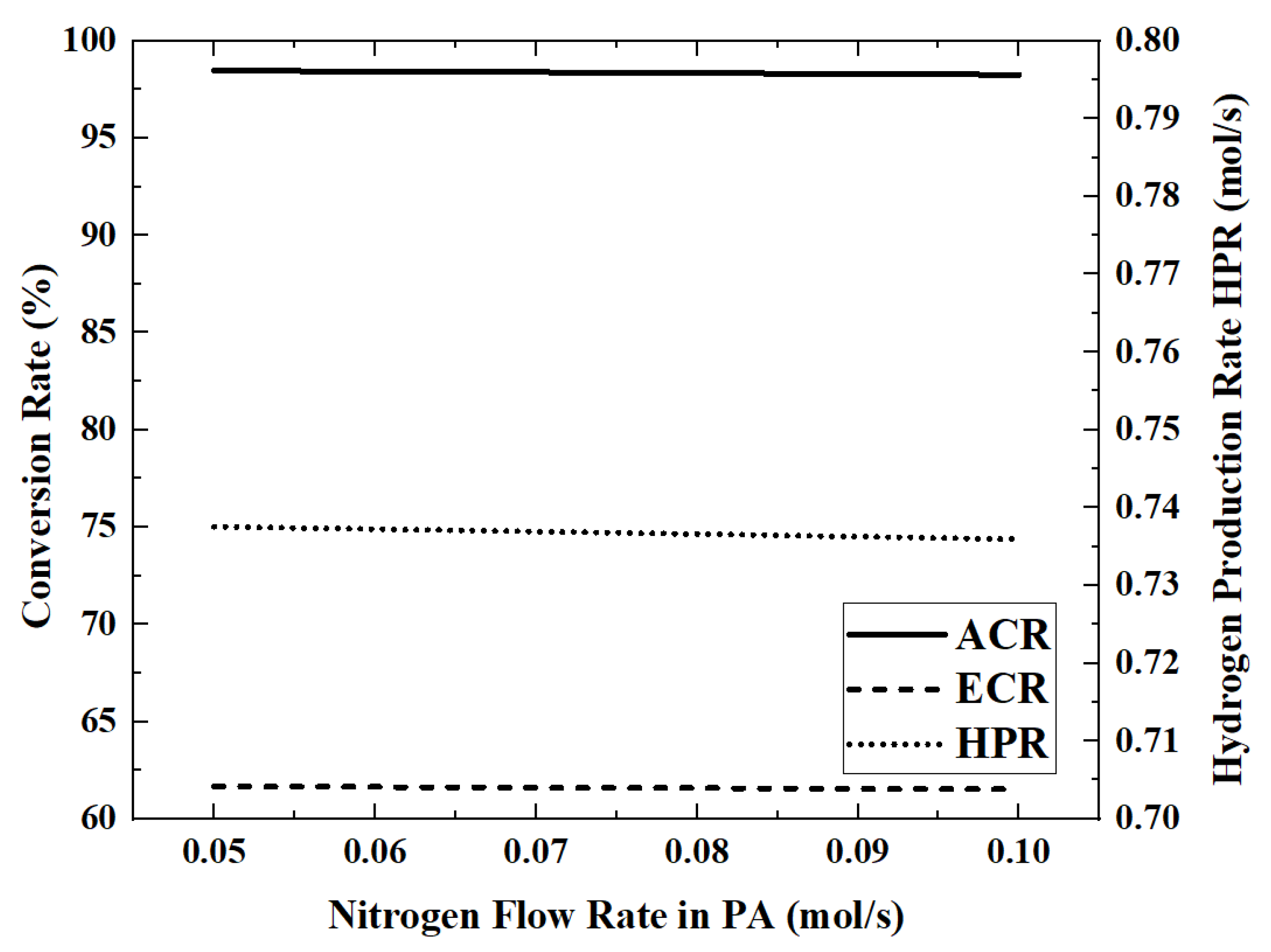
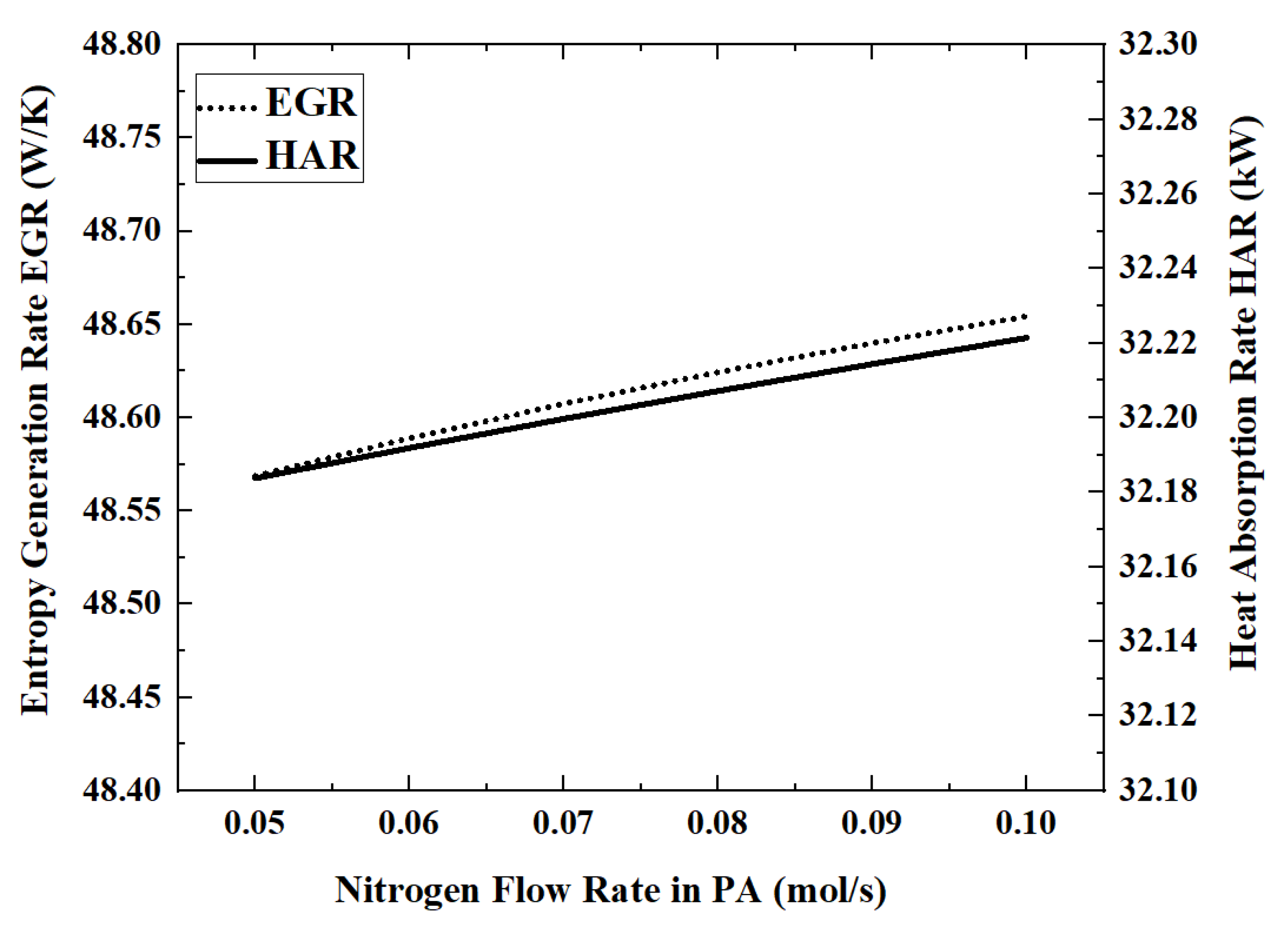
In this model, the permeated hydrogen is removed by nitrogen co-current sweeping in the permeation zone. Therefore, the nitrogen flow rate will affect the hydrogen permeation rate, which in turn affects the reactor performance. The performance index changes that occur when the nitrogen flow rate is increased from 0.05 mol/s to 0.1 mol/s are shown in
Figure 12 and
Figure 13.
When the flow rate of nitrogen is 0.1 mol/s, the maximum HAR is 32.22 kW. The influence of nitrogen flow rate on the performance of the reactor is very weak. By increasing the nitrogen flow rate from 0.05 mol/s to 0.1 mol/s, the ACR and HPR decrease by about 0.1%. The higher nitrogen flow rate will take away more energy, which will cause the reaction temperature to become lower. For example, when the nitrogen flow rate increases from 0.05 mol/s to 0.07 mol/s to 0.09 mol/s, the outlet temperature of the reaction zone decreases from 701.5 K to 697.5 K to 693.4 K.
4. Conclusions
In this paper, the model of a solar-heated ammonia decomposition membrane reactor using nitrogen sweeping is established, and five performance indicators (ACR, HPR, EGR, HAR and ECR) are set considering the scenarios of clean energy hydrogen production and solar energy storage. The effects of the light intensity, ammonia flow rate, nitrogen flow rate and permeable membrane radius on system performance were analyzed according to these indicators. The conclusion is as follows:
For the reference reactor, the ACR is 98.4%, the HPR is 0.74 mol/s, the EGR is 48.61 W/K, the HAR is 32.2 kW and the ECR is 61.6%.
The two parameters of light intensity and ammonia flow rate have a very significant impact on the system performance, which can reach more than 70%. These two parameters will be the key optimization parameters in industrial design. The membrane radius has only a little effect on the system performance, with a performance change of about 1.2%. The effect of the nitrogen flow rate on system performance is less than 0.2%.
When the light intensity is increased from 500 W/m2 to 800 W/m2 (60% increase), the ACR, EGR, HAR and HPR increase by 36.2%, 39.6%, 58.5% and 36.2%, respectively, while the ECR decreases by 14.2%.
When the ammonia flow rate is increased from 0.3 mol/s to 0.6 mol/s (100% increase), the ECR, EGR, HAR and HPR increase by 73.6%, 71.7%, 15.6% and 74.3%, respectively, while the ACR decreases by 12.9%.
To avoid the premature complete decomposition of ammonia, the setting of the ammonia gas flow rate needs to match the light intensity.
Author Contributions
Conceptualization, T.X. and S.X.; Funding acquisition, S.X.; Methodology, T.X. and S.X.; Software, J.H., Q.J. and T.X.; Validation, S.X.; Writing—original draft, T.X. and C.W.; Writing—review and editing, S.X. All authors have read and agreed to the published version of the manuscript.
Funding
This work is supported by the National Natural Science Foundation of China (Grant No. 51976235), the Key Research and Development Project of Hubei Province (Grant No.2022BID011) and the Independent Research and Development Project of Naval University of Engineering (No. 2022502150).
Institutional Review Board Statement
Not applicable.
Informed Consent Statement
Not applicable.
Data Availability Statement
Not applicable.
Conflicts of Interest
The authors declare no conflict of interest.
References
- Lovegrove, K. Exergetic optimization of a solar thermochemical energy storage system subject to real constraints. Int. J. Energy Res. 1993, 17, 831–845. [Google Scholar] [CrossRef]
- Lovegrove, K.; Luzzi, A. Endothermic reactors for an ammonia based thermochemical solar energy storage and transport system. Sol. Energy 1996, 56, 361–371. [Google Scholar] [CrossRef]
- Lovegrove, K.; Kreetz, H.; Luzzi, A. The first ammonia based solar thermochemical energy storage demonstration. J. Phys. IV 1999, 9, 581–586. [Google Scholar] [CrossRef]
- Lovegrove, K.; Luzzi, A.; Soldiani, I.; Kreetz, H. Developing ammonia based thermochemical energy storage for dish power plants. Sol. Energy 2004, 76, 331–337. [Google Scholar] [CrossRef]
- Lovegrove, K.M. Aspects of Thermochemical Storage and Transfer of Solar Energy Using Ammonia; Australian National University: Canberra, Australia, 1992. [Google Scholar]
- Luzzi, A. Solar Thermo-Catalytic Ammonia Dissociation; Australian National University: Canberra, Australia, 1996. [Google Scholar]
- Luzzi, A.; Lovegrove, K.; Filippi, E.; Fricker, H.; Schmitz-Goeb, M.; Chandapillai, M.; Kaneff, S. Techno-economic analysis of a 10 MW solar thermal power plant using ammonia-based thermochemical energy storage. Sol. Energy 1999, 66, 91–101. [Google Scholar] [CrossRef]
- Kreetz, H.; Lovegrove, K. Exergy analysis of an ammonia synthesis reactor in a solar thermochemical power system. Sol. Energy 2002, 73, 187–194. [Google Scholar] [CrossRef]
- Kreetz, H.; Lovegrove, K.; Luzzi, A. Maximizing thermal power output of an ammonia synthesis reactor for a solar thermochemical energy storage system. J. Sol. Energy Eng. 2001, 123, 75–82. [Google Scholar] [CrossRef]
- Kreetz, H.; Lovegrove, K. Theoretical analysis and experimental results of a 1 kW ammonia synthesis reactor for a solar thermochemical energy sotrage system. Sol. Energy 1999, 67, 287–296. [Google Scholar] [CrossRef]
- Wang, X.G.; Wei, Y.D.; Zhang, J.; Xu, Y.F.; Xu, H.Y.; Li, W.Z. High-performance Pd membrane and its application in H2 production from NH3 decomposition (in Chinese). J. Chem. Ind. Eng. 2006, 12, 2897–2901. [Google Scholar]
- Rizzuto, E.; Palange, P.; Del Prete, Z. Characterization of an ammonia decomposition process by means of a multifunctional catalytic membrane reactor. Int. J. Hydrogen Energy 2014, 39, 11403–11410. [Google Scholar] [CrossRef]
- Itoh, N.; Kikuchi, Y.; Furusawa, T.; Sato, T. Tube-wall catalytic membrane reactor for hydrogen production by low-temperature ammonia decomposition. Int. J. Hydrogen Energy 2021, 46, 20257–20265. [Google Scholar] [CrossRef]
- Itoh, N.; Oshima, A.; Suga, E.; Sato, T. Kinetic enhancement of ammonia decomposition as a chemical hydrogen carrier in palladium membrane reactor. Catal. Today 2014, 236, 70–76. [Google Scholar] [CrossRef]
- Cechetto, V.; Di Felice, L.; Medrano, J.A.; Makhloufi, C.; Zuniga, J.; Gallucci, F. H2 production via ammonia decomposition in a catalytic membrane reactor. Fuel Process. Technol. 2021, 216, 106772. [Google Scholar] [CrossRef]
- Abashar, M.E.E.; Al-Sughair, Y.S.; Al-Mutaz, I.S. Investigation of low temperature decomposition of ammonia using spatially patterned catalytic membrane reactors. Appl. Catal. A-Gen. 2002, 236, 35–53. [Google Scholar] [CrossRef]
- Abashar, M. The impact of ammonia feed distribution on the performance of a fixed bed membrane reactor for ammonia decomposition to ultra-pure hydrogen. Int. J. Hydrogen Energy 2019, 44, 82–90. [Google Scholar] [CrossRef]
- Wang, B.; Kong, H.; Wang, H.; Wang, Y.; Hu, X. Kinetic and thermodynamic analyses of mid/low-temperature ammonia decomposition in solar-driven hydrogen permeation membrane reactor. Int. J. Hydrogen Energy 2019, 44, 26874–26887. [Google Scholar] [CrossRef]
- Xie, T.C.; Xia, S.J.; Kong, R.; Li, P.L.; Wang, C. Performance analysis of ammonia decomposition endothermic membrane reactor heated by trough solar collector. Energy Rep. 2022, 8, 526–538. [Google Scholar] [CrossRef]
- Xie, T.C.; Xia, S.J.; Jin, Q.L. Thermodynamic optimization of ammonia decomposition solar heat absorption system based on membrane reactor. Membranes 2022, 12, 627. [Google Scholar] [CrossRef]
- Bejan, A. Notes on the history of the method of entropy generation minimization (finite time thermodynamics). J. Non-Equil. Thermodyn. 1996, 21, 239–242. [Google Scholar]
- Bejan, A. The concept of irreversibility in heat exchanger design: Counterflow heat exchangers for gas-to-gas applications. J. Heat Trans. 1977, 99, 374–380. [Google Scholar] [CrossRef]
- Chen, L.G.; Xia, S.J. Processes in generalized thermodynamic dynamic-optimization of irreversible process. Sci. China Technol. Sci. 2019, 49, 981–1022. [Google Scholar]
- Chen, L.G.; Xia, S.J.; Feng, H.J. Processes in generalized thermodynamic dynamic-optimization of irreversible cycles. Sci. China Technol. Sci. 2019, 49, 1223–1267. [Google Scholar]
- Chellappa, A.S.; Fischer, C.M.; Thomson, W.J. Ammonia decomposition kinetics over Ni-Pt/Al2O3 for PEM fuel cell applications. Appl. Catal. A-Gen. 2002, 227, 231–240. [Google Scholar] [CrossRef]
- Di Carlo, A.; Vecchione, L.; Del Prete, Z. Ammonia decomposition over commercial Ru/Al2O3 catalyst: An experimental evaluation at different operative pressures and temperatures. Int. J. Hydrogen Energy 2014, 39, 808–814. [Google Scholar] [CrossRef]
- Prasad, V.; Karim, A.M.; Arya, A.; Vlachos, D.G. Assessment of overall rate expressions and multiscale, microkinetic model uniqueness via experimental data injection: Ammonia decomposition on Ru/γ-Al2O3 for hydrogen production. Ind. Eng. Chem. Res. 2009, 48, 5255–5265. [Google Scholar] [CrossRef]
- Morreale, B.D.; Ciocco, M.V.; Enick, R.M.; Morsi, B.I.; Howard, B.H.; Cugini, A.V.; Rothenberger, K.S. The permeability of hydrogen in bulk palladium at elevated temperatures and pressures. J. Membr. Sci. 2003, 212, 87–97. [Google Scholar] [CrossRef]
- Hicks, R.E. Pressure Drop in packed beds of spheres. Ind. Eng. Chem. Fundam. 1970, 9, 500–502. [Google Scholar] [CrossRef]
- Li, P.L.; Chen, L.G.; Xia, S.J.; Kong, R.; Ge, Y.L. Total entropy generation rate minimization configuration of a membrane reactor of methanol synthesis via carbon dioxide hydrogenation. Sci. China Technol. Sci. 2022, 65, 657–678. [Google Scholar] [CrossRef]
- Kong, R.; Chen, L.G.; Xia, S.J.; Zhang, L.; Feng, H.J. Minimization of entropy generation rate during hydrogen iodide decomposition reaction process. Sci. China Technol. Sci. 2021, 51, 565–579. [Google Scholar] [CrossRef]
- Xie, T.C.; Xia, S.J.; Wang, C. Multi-objective optimization of Braun-type exothermic reactor for ammonia synthesis. Entropy 2021, 24, 52. [Google Scholar] [CrossRef]
- Li, P.L.; Chen, L.G.; Xia, S.J.; Zhang, L. Maximum hydrogen production rate optimization for tubular steam methane reforming reactor. Int. J. Chem. React. Eng. 2019, 17, 20180191. [Google Scholar] [CrossRef]
- Li, P.L.; Chen, L.G.; Xia, S.J.; Zhang, L.; Kong, R.; Ge, Y.L.; Feng, H.J. Entropy generation rate minimization for steam methane reforming reactor heated by molten salt. Energy Rep. 2020, 6, 685–697. [Google Scholar] [CrossRef]
- Li, P.L.; Chen, L.G.; Xia, S.J.; Zhang, L. Entropy generation rate minimization for methanol synthesis via a CO2 hydrogenation reactor. Entropy 2019, 21, 174. [Google Scholar] [CrossRef] [PubMed]
- Kong, R.; Chen, L.; Xia, S.; Li, P.; Ge, Y. Minimization of Entropy Generation Rate in Hydrogen Iodide Decomposition Reactor Heated by High-Temperature Helium. Entropy 2021, 23, 82. [Google Scholar] [CrossRef] [PubMed]
- Kong, R.; Chen, L.; Xia, S.; Li, P.; Ge, Y. Performance analysis of hydrogen iodide decomposition membrane reactor under different sweep modes. Energy Convers. Manag. 2021, 244, 114436. [Google Scholar] [CrossRef]
| Publisher’s Note: MDPI stays neutral with regard to jurisdictional claims in published maps and institutional affiliations. |
© 2022 by the authors. Licensee MDPI, Basel, Switzerland. This article is an open access article distributed under the terms and conditions of the Creative Commons Attribution (CC BY) license (https://creativecommons.org/licenses/by/4.0/).

