Abstract
In this work, the preparation of dense blended membranes, from blends of poly(vinylidene fluoride) (PVDF), poly(ether sulfone) (PES) and polyethyleneimine (PEI) or Fumion®, with possible applications in alkaline fuel cell (AEMFC) is reported. The blended PEI/Fumion® membranes were prepared under a controlled air atmosphere by a solvent evaporation method, and were characterized regarding water uptake, swelling ratio, thermogravimetric analysis (TGA), infrared spectroscopy (FT-IR), scanning electron microscopy (SEM), ion exchange capacity (IEC), OH− conductivity and novel hydroxide ion exchange rate (HIER), which is related to the mass transport capacity of the OH− ions through the membrane. The effect of the chemical composition on its morphological and anion exchange properties was evaluated. It was expected that the usage of a commercial ionomer Fumion®, in the blended membranes would result in better features in the electrical/ionic conductivity behaviour. However, two of the membranes containing PEI exhibited a higher HIER and OH− conductivity than Fumion® membranes, and were excellent option for potential applications in AEMFC, considering their performance and the cost of Fumion®-based membranes.
1. Introduction
Due to continuous human population growth, global energy demand increases year by year. Humanity’s energy requirements are closely related to the social, health and economic issues that society demands [1]. During the second half of the 18th century, coal began as the preferred fuel power source for steam engine operation resulting in the world entering the fuel era with the spread of the industrial revolution. Coal produces more heat during combustion compared to biomass-based fuels. The use of coal as fuel was chosen because it was a more affordable option than other choices [2]. Nevertheless, the use of this type of fuel for the usage power generation led to environmental consequences, the most critical of which is climate change, as reported by Peterson [3]. In addition, the depletion of petroleum, natural gas and coal resources has economic impacts. To avoid these issues, governments around the world have adopted new policies and regulations regarding CO2 emissions to establish use of renewable energy sources (RES) in national systems, leading to the development of technologies by which different RES can be exploited to satisfy society’s energy demand. The fluctuating nature of different RES represents one of the biggest challenges to overcome in the integration of the RES to the electrical energy network. Unfortunately, RES depends on several conditions, such as location, time, and season, e.g., wind power profiles vary over minutes, hours, and days, while peaking at night when demand is low. During the day, wind power can be a few gigawatts (GW) at some time and only a few megawatts (MW), or even zero, at others. The intermittency of RES results in spatial and temporal gaps between the availability of energy and its consumption by end users. Therefore, reliable energy storage systems must be developed to mitigate these issues [4,5,6,7,8,9]. In Mexico, it is projected for the year 2050 that only 50% of the electric energy will be generated from fossil sources [10]. RES are continually restored by nature, are derived directly from solar energy, or indirectly from wind, or other natural sources such as tidal and geothermal. Unlike fossil fuels, RES does not generate waste, converting this natural energy into forms of usable energy such as electrical and heat energy in a clean manner [11].
It is well known that there are different devices for storage of electrical energy, such as mechanical, chemical and thermal storage [12]. Chemical storage is based on the use of different electrochemical devices to generate electrical energy by two approaches: (i) electrical charge accumulation, such as capacitors and super capacitors, and (ii) by redox reactions such as batteries and fuel cells. The latter electrochemical devices have larger power density in comparison with capacitors and super capacitors, and are ideal devices for portable and stationary technologies [13,14]. A hydrogen fuel cell converts chemical energy directly into electricity, producing only water and heat as by-products, and can supply energy with efficiencies above 80% in contrast with thermal devices that operate under the Carnot cycle [15]. Five types of fuel cells can be distinguished mainly by the type of electrolyte, such as polymeric exchange membrane fuel cells (PEMFC/AEMFC), phosphoric acid fuel cells (PAFC), molten carbonate fuel cells (MCFC) and solid oxide fuel cells (SOFC) [16]. A PEMFC consists of an ionic exchange membrane in contact with two electrodes on both sides. Depending upon the transferred ionic species, the technology is classified as an anion (OH−) or proton (H+) exchange membrane fuel cell (AEMFC, and PEMFC, respectively). AEMFCs offer the possibility of Pt-free cathode electrodes, with simpler kinetics, a lower fuel crossover and the reduction of CO poisoning. This makes AEMFCs a more affordable technology than PEMFCs. However, PEMFCs have been widely studied, with improvements over AEMFCs such as better water management, higher ionic conductivity and increasing durability in proton exchange membranes. The process of carbonation is one of the main drawbacks of AEMFCs because some CO2 from the air is incorporated into the system reacting with OH− producing CO32− and HCO3−. This decreases anion conductivity in AEM, and these ions are bigger than OH− ion, which reduces AEM conductivity [17,18,19,20,21]. One aspect to consider for AEMFCs is the poor stability of ammonium groups used for hydroxide ion conductivity because this kind of cation is susceptible to react under conditions of the AEMFC by either SN2 or E2 reactions [22,23,24,25].
AEMFC and PEMFC technologies exhibit great versatility, allowing operation with a large number of fuels, such as alcohol, ammonia, and hydrocarbon compounds. Hydrogen is the best option due to carbon-free by-products (with no contribution to the greenhouse effect), which otherwise could cause deactivation of the electrodes attached to the membrane because of the adsorption phenomenon. Hydrogen is continuously fed towards the anode, while the oxygen coming from the air is directly supplied to the cathode. The chemical reactions that take place during operation of the AEMFC are shown below (Equation (1) (hydrogen oxidation reaction, HOR) and Equation (2) (oxygen reduction reaction, ORR), respectively) [26]:
AEMFC technologies can use a liquid fuel for the oxidation reaction such as ethanol, methanol, glycerol, ethylene glycol and some N-based fuels such as hydrazine, urea and ammonia [27,28,29,30,31,32]. However, AEMFCs using hydrogen as fuel are preferred because they have better OCV potentials and have a minimal environmental impact due to the absence of CO2 in the electrochemical reactions [33].
The capacity of OH− transport at the membrane determines the performance of the AEMFC, since the OH− ions must migrate from the cathode to the anode. Chan et al. reported amination in aqueous solutions of different chlorinated polymers via a hydrothermal process, where conventional polymers such as chlorinated polypropylene were functionalized with polyethyleneimine (PEI), obtaining conductivities in the order of 10−2 S cm−1. Since the membrane exhibited a large porosity, the high conductivity was attributed to functionalization with ammonium groups [34].
Lee et al. [35] prepared membranes with a blend of copolymer stryren-co-vinylimidazole and polyvinyl alcohol. These membranes were used for alkaline water electrolysers. The authors reported that a phase separation took place with increased imidazole ratio, yielding hydrophilic channels for ion conductivity.
Wu et al. [36] prepared membranes of quaternized polyether ether ketone (q-PEEK) with a piperidinium cation and polybenzimidazole. The authors reported that all membranes exhibited good miscibility due to a hydrogen bond between the piperidinium cation and N atoms in the main skeleton of polybenzimidazole.
Kerres et al. [37] prepared blended membranes from poly(2,6-dimethyl-1,4-phenyleneoxide). Partially fluorinated polybenzimidazole as the polymer matrix, polyethersulfone was used to create an acid-base crosslinking. Furthermore, the authors used fluorinated polybenzimidazole as an inert polymer to increase mechanical resistance.
Henkensmeier et al. [38] prepared membranes from blends of polybenzimidazole (mPBI) with Fumion® doped with KOH at different mass ratios, finding that all blended membranes exhibited higher values of ionic conductivity than mPBI membranes. One material showed up to 80% higher conductivity. The authors concluded that the weight percent of KOH as a dopant affects all the evaluated properties of membranes. This group studied similar membranes for other devices, such as vanadium redox flow batteries, where the authors observed that blended membranes showed similar results to a commercial membrane (Nafion®) [39].
Ramontja et al. [40] studied membranes from quaternized poly(2,6-dimethyl-1,4-phenyleneoxide) and polysulfone (PSf), two rigid polymers due to their aromatic structure. By SEM analysis, the authors found that by increasing the PSf content, the membrane surface showed less imperfections due to better compatibility, yielding a material with great mechanical properties.
In this paper the preparation of different anion exchange membranes containing either Fumion® or PEI as OH− conductive polymers is reported. The content of such ionomers ranged from 3–6% in the blended membranes. Additionally, the feasibility of its potential use as an anion exchange fuel cell solid state electrolyte was established, and as a strategy to reduce the cost of this component in AEMFC by using a lesser quantity of ionomer.
2. Experimental Section
2.1. Reagents
Pellets of polyvinylidene fluoride (PVDF) (MW = 530,000); polyethyleneimine (PEI, water free; MW = 10,000, N-methyl-2-pyrrolidone (NMP, 99.98%) anhydrous and hydrochloric acid (37%) were purchased from Sigma Aldrich. Polyethersulfone (PES, ≥99%; MW = 30,000) was acquired from Imperial Chemical Industry. Fumion® (≈10 wt% solution in NMP) was purchased from Fuel Cell Store. Sodium hydroxide (97%) and FeSO4·7H2O (>99%) were obtained from Jalmek, phenolphthalein ACS reagent grade and H2O2 (30%) were purchased from Fagalab.
2.2. Membrane Preparation
Polymeric membranes were prepared by a solvent evaporation method using different chemical compositions. PVDF, PES and PEI were dissolved in NMP at room temperature to obtain a solution with 16 wt% of solid content. For the solution containing Fumion®, the NMP added was adjusted because this commercial ionomer is already dissolved in the same solvent. The structure of this ionomer is not well known, but has quaternary ammonium groups for hydroxide ion conduction [41]. The casting solution was poured onto a clean glass plate placed in a membrane casting device (for polymeric solution containing PEI it was heated to 60 °C for 2 h in order to minimize the effect of viscosity during casting knife procedure). Afterwards, the glass plate/membrane was placed into a convection oven at 30 °C for 24 h to remove the solvent in a controlled environment. Finally, the membranes were removed from the glass plate by immersing it in DI water at room temperature. The concentration of PEI or Fumion® ranged from 3 to 6 wt%. To study the effect of the polymer on the performance of the membrane, the PES content varied from 0 and 3 wt%, since it should not be in a higher proportion than PEI or Fumion®. The PVDF content was fixed at 10 wt% for all membranes. The composition of the prepared membranes is described in Table 1.

Table 1.
Chemical composition and thicknesses of the membranes PVDF/PES and PEI or Fumion®.
2.2.1. Quaternization of PEI/PVDF Membranes
The different PEI functionalized membranes were quaternizated according to the method reported by Eyal and Canari [42], which consists of an acid-base titration, where sufficiently basic amines form H-bonds and cause ion pair formation. Zapata-Gonzalez et al. reported pKa values of polymers with tertiary amines about 7.5 [43]. A slight modification to the Eyal method was used consisting of the substitution of deionized waster by methanol to prepare the 1.0 M HCl. For membranes containing Fumion®, this step was not required since the ionomer is in ionic form.
2.2.2. Alkaline Treatment of Membranes
The quaternizated membranes were immersed in a 1.0 M NaOH solution at room temperature for 12 h to replace the hydroxyl (OH−) groups at the membrane surface. After this procedure the membranes were washed with DI water until the pH of the remaining solution was neutral. All the membranes were stored in DI water for further characterization.
2.3. Membrane Characterization
2.3.1. Fourier Transform Infrared (FT-IR) Spectroscopy
The chemical composition of the membranes surfaces was characterized by FT-IR spectroscopy (Perkin Elmer Spectrum 100) with an attenuated total reflectance device. The membranes were scanned in the range of 600–4000 cm−1 with a resolution of 2 cm−1 and 16 scans.
2.3.2. Scanning Electron Microscopy (SEM), Energy Dispersive Spectroscopy (EDS) and Atomic Force Microscopy (AFM)
The acquisition of SEM images was carried-out with a microscope (TESCAN, VEGA 3) operated at an accelerating voltage of 15 kV. Previous to analysis, all samples were sputter-coated with gold (99.999%) at 18 mA for 4 min using a SPI-MODULE sputter coater. The presence of polymer blends on the surface membranes were observed semi-quantitatively by energy dispersive X-ray spectroscopy (EDS) by mapping measurements on cross-sections using a Bruker XFlash 4010. EDS information was processed using Quantax 200 ESPRIT 1.9 software. AFM analyses were carried out using a microscope (Easyscan 2 Nanosurf) with a scanned area of 100 μm × 100 μm in contact mode.
2.3.3. Thermogravimetric Analysis (TGA)
Thermogravimetric analysis of PEI or Fumion®/PVDF/PEI membranes was performed with a TGA Q500 TA Instrument by using a Pt pan. Thermograms were recorded at a temperature range of 30 °C to 800 °C, and a heating rate of 20 °C min−1 under a nitrogen atmosphere (60 L min−1).
2.3.4. Water Uptake (WU) and Swelling Ratio (SR)
The WU and SR of PEI, Fumion® and PVDF/PES membranes, in OH− form, were calculated by changes of the mass and thickness of the swollen and dried membranes. Each membrane was kept in DI water for 24 h, then excess water was removed with tissue paper and the weight of the wet membrane was recorded and its thickness measured with a Mitutoyo 547–400S. Then, the wet membranes were dried in an oven at 60 °C until constant weight and thickness were measured. WU and SR of membranes were calculated from Equations (3) and (4), respectively:
where mwet, mdry, Lwet and Ldry are the weight and the thickness of the swollen and dried membranes, respectively, and Lwet and Ldry are the thicknesses of fully swollen and dried membranes, respectively.
2.3.5. Ion Exchange Capacity (IEC)
The IEC of membranes was measured using an acid-base titration method as reported in a previous study [44]. The membranes were cut in pieces of 2 cm × 2 cm, then immersed in 10 mL of 0.1 M HCl and kept for 24 h to ensure the consumption of OH− with H+. Then, the remaining acidic solution was transferred to a flask and titrated with 0.1 M NaOH using phenolphthalein (1%) as indicator. The IEC of membranes was recorded in meq of H+ g−1 and was determined by the difference in the number of milliequivalents of HCl solution before (meq of HCl)0 and after (meq of HCl)f, the membrane being neutralized, according to the Equation (5)
IEC = [(meq of HCl)0 − (meq of HCl)f]/mass of dry membrane (g)
2.3.6. Hydroxide Ion Conductivity
Anionic conductivity was measured by electrochemistry impedance spectroscopy (EIS) using a four probe H-cell configuration (Figure 1a). Impedance spectroscopy was obtained in a frequency range of 1 MHz-10 Hz with a potential amplitude of 10 mV, using a BioLogic VMP-300 potentiostat. Platinum plates (1 cm × 1 cm) and an Ag/AgCl electrode were used as work and reference electrodes, respectively. NaOH 1.0 M solution was used as the electrolyte. The membranes were cut into squares of 2 cm × 2 cm and placed between the two compartments of the H-type cell. OH− conductivity was calculated by Equation (6):
where σ is the hydroxide conductivity in mS cm−1, Rmem was the difference between the cell with only an electrolyte (blank signal) and a cell with a membrane (Rmem+electrolyte), L is width of membrane in cm, A is the contact area of membrane with the electrolyte solution in cm2, and ER is the specific electric resistance of the membrane in Ω cm2, taking into account the effective area exposed during the measurement [45]. All membranes were measured at room temperature.
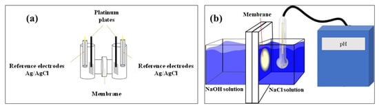
Figure 1.
(a) H cell configuration for anionic conductivity. (b)Two compartment cell for hydroxide ions exchange rate determination.
2.3.7. Hydroxide Ion Exchange Rate (HIER)
To evaluate the HIER of membranes, a laboratory-made acrylic cell with two compartments was used (Figure 1b). During the test, a sample of the membrane was placed between the two compartments then one compartment was filled up with 250 mL solution of NaOH 2.0 M and the other compartment with 250 mL NaCl 2.0 M in order to keep constant the ionic strength in both compartments and induce mass transport of the OH− through the membrane. A pH electrode was immersed in the NaCl compartment to record the pH every minute for 24 h. All experiments were kept at room temperature and under magnetic stirring to minimize the concentration polarization. All membranes were treated with 2.0 M NaOH for 24 h previous to each experiment. The prepared blended membranes were compared with the commercial membrane, Fumapem®. The aim of this measurement was to determine the permeation capacity of the ionic species through the membrane, which is desirable in AEMFCs because the OH− ions generated at the cathodic compartment are consumed in the anodic compartment. Although ion conductivity is a measurement associated with the mobility of the ion, in most experimental designs the transport of the ionic species trough the membrane is not considered.
2.3.8. Oxidative Stability of Membranes
During the operation of AEMFCs, the membranes can suffer from oxidative stress resulting from reactive oxygen species involved in the cathodic reaction. To determine the stability of the polymeric membranes against the oxidative species, a membrane sample of each composition was immersed into Fenton reagent (4% of H2O2 + 3 ppm of FeSO4 at 50 °C) for 120 h, the samples were dried overnight and weighed. The stability of the membrane is related to the weight registered after oxidative stress [46].
3. Results and Discussion
3.1. Synthesized Membranes
In this work, two series of membranes were developed with different concentrations of ionomer (PEI or Fumion®) responsible of OH− transport in the membrane. Hence, four membranes containing PVDF/PES/PEI (labelled M1–M4) and four membranes containing PVDF/PES/Fumion® (labelled F1–F4) were prepared. Table 1 shows the composition and thicknesses of all membranes. The chemical composition refers to that of the polymer solution used to prepare such a membrane.
3.2. FT-IR Analysis
Figure 2a shows the FT-IR spectra of the membranes prepared with PVDF/PES/PEI (M1–M4). The peak at 3300 cm−1 corresponds to water, which means that at a higher concentration of PEI the surface is more hydrophilic. At 3020 cm−1 the signal ascribed to C-H of alkenes appears due to the presence of PES in membranes. The peak at 2980 cm−1 is associated to the stretching of aliphatic C-H due to PEI or PVDF. At 1650 cm−1 a very clear peak appears for bond the C=C bond. Another characteristic signal related to PVDF is the peak at 1070 cm−1 [47], ascribed to the absorption of asymmetrical stretching of CF2. The signal at 1144 cm−1 [48] is caused by symmetric stretching for S=O. The signal at 1170 cm−1 for M1 is split into two small peaks for the case of M2–M4 due to the symmetric stretching of the S=O group. The signal at 1570 cm−1, due to the bending of N-H, reveals the presence of PEI in the membrane [49]. Figure 2b shows spectra of the membranes containing Fumion® as ionomer. The specification sheet for FAA-3-SOLUT-10 mentions that it contains aromatic polymers, whose signal appears at 3020 cm−1, as indicated by the company. All membranes of this series showed signals for PES and for C-H corresponding to the methylene of PVDF. The peak at 1600 cm−1 is due to the C=C bond of PES and polymer aromatics of Fumion®. The signal for flexion N-H appears at 1570 cm−1 and the asymmetrical stretching of CF2 for PVDF appears at 1070 cm−1.
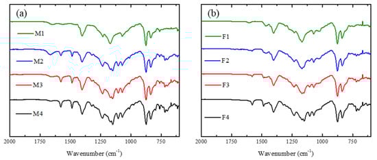
Figure 2.
FT-IR spectra of the synthesized membranes containing: (a) PEI and (b) Fumion®.
3.3. Scanning Electron Microscope (SEM), Energy Dispersive Spectroscopy (EDS) and Atomic Force Microscope (AFM)
SEM micrographs are shown in Figure 3 and Figure 4. The analysed surface corresponds to that exposed to the air during preparation. Figure 3 shows SEM images for PEI-based membranes. M1 (Figure 3a) has a more heterogeneous surface that indicates a higher porosity, which could promote the transference of OH− through membrane, and also suggests a higher surface area. M2 and M3 (Figure 3b,c) present a more homogeneous surface, which could result from a better chemical mixing of both polymeric solutions. In the case of M4, a heterogeneous surface similar to M1 can be observed. In the latter, this may due to poor miscibility between PVDF and PEI because PEI is a hydrophilic polymer and PVDF is a hydrophobic polymer due to the C-F bond. M4 has a pore-like structure on the surface, which can be related to the composition solution. This membrane is composed of a mass ratio of PEI/PES equal to 1, probably induced by competition between these two polymers during membrane formation.
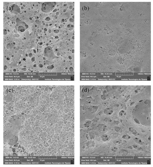
Figure 3.
SEM images for membranes containing PEI: (a) M1, (b) M2, (c) M3 y (d) M4.
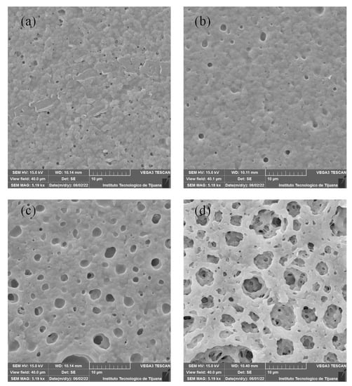
Figure 4.
SEM images of membranes containing Fumion®: (a) F1, (b) F2, (c) F3 y (d) F4.
SEM images for Fumion®-based membranes are shown in Figure 4. These membranes exhibit a more homogenous surface than the PEI-based membranes, and a pore-like pattern is observed in these membranes. With increased concentrations of PES, a greater pore size was detected. Figure 4a shows that the F1 membrane exhibits low porosity and has a homogeneous surface that could be related to good compatibility between PVDF and Fumion®. F2 and F3 show repetitive pore-like patterns on the surface, indicating that the casting knife method was suitable for preparing this kind of membrane, depending on the cast solution and type of substrate used. Membrane F4 has a greater pore size compared to other membranes, this is because of competition between Fumion® and PES, showing poor compatibility between these two polymers.
Cross-section micrographs of membranes M1-M4 and F1-F4 are presented in Figure 5. SEM images for M1 and M4 (Figure 5a) reveals that M1 has a structure with a greater porosity than M4. The main parameters favouring this structure are low stability of the components in the polymeric solution, tending to separate, as well as the flux of the solvent evaporating during the preparation process. PES and PEI exhibited less miscibility between them than the Fumion® membranes series. Figure 5b shows SEM images for F1 and F4 where both cross sections are very similar. F4 shows a slightly porous structure due to the incorporation of PES that has the property of creating free spaces due to interaction with PVDF. Although M1 exhibited high apparent porosity, the cross section shown in Figure 5a is around the first 5 µm from the edge, but the total thickness is 60 µm. The cross-section micrographs of all membranes in a wider scale of 20 µm is shown in Supporting Information. Figure S1 corresponds to PEI-based membranes and Figure S2 to Fumion®-based membranes. M1 shows the same relatively porous structure at the edge, becoming more tortuous in the middle, and reaching a dense region at higher depths. At this deep region, there are no perceptible transport channels that could allow the crossover of gases during the energy conversion process. This heterogeneous structure (porous at the edge, denser at the center of the membrane) favours the deposition of catalysts, since this increases dispersion and avoids the crossover of gases. Opposite to this behaviour, Fumion®-based membranes exhibited a homogeneous and denser structure, where there was a high probability of catalyst agglomeration and a low permeation of gases through the catalytic layer.
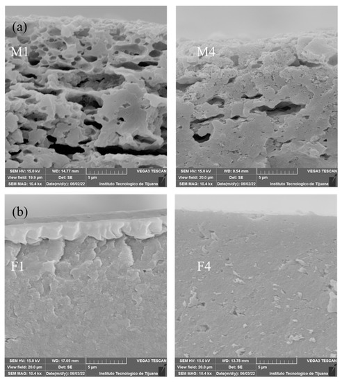
Figure 5.
SEM images for membranes: (a) M1 and M4 and (b) F1 and F4.
EDS analysis of membranes was recorded to verify the chemical composition of the surfaces. Figure 6 shows spectra for the membranes containing PEI, where the constituent elements of each polymer in the membrane was detected. It is important to highlight M4 where sulphur is absent, which is consistent with the chemical composition of casting solution. Another important issue is the presence of nitrogen in all series of membrane.
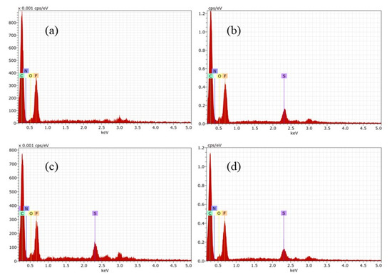
Figure 6.
EDS for membranes containing PEI: (a) M1, (b) M2, (c) M3 y (d) M4.
Similar investigation was done for Fumion®-based membranes. The preparation was successful, and the EDS matched with FT-IR analysis. EDS confirmed the presence of elements of each polymer, such as fluorine coming from PVDF, sulphur from PES, and counter ion Br in the case of the commercial ionomer Fumion®. In each spectrum there is a signal of this element. F1 in Figure 7a shows the absence of sulphur.
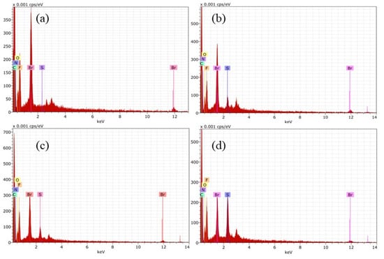
Figure 7.
EDS for Fumion®-based membranes: (a) F1, (b) F2, (c) F3 y (d) F4.
The ratios between N/F and N/C were calculated for all membranes. These elements were selected because N is in the functional group responsible for ion exchange and F and C are present in all polymeric matrices. The results are shown in Table 2 and were taken from the surface.
Table 2.
Elemental ratios of N/F and N/C of the synthesized membranes.
The N/F ratio in both sets of membranes has the same trend; having a lower value for the membranes with 6 wt% of ionomer, and increasing for membranes with 5 wt%, then decreasing as the ionomer content decreases. This behavior can be related to the morphology at the surface due to the preparation method, although it does not necessarily correspond to the distribution in the internal structure of the membranes.
For evaluation of membrane surfaces, AFM analysis was performed. In Figure 8, M1 and M4 show a rough topography, and SEM images show these two have a higher surface area, indicating that these two membranes are capable of attaching a higher quantity of hydroxide ions. M2 and M3 have a smoother surface (mean roughness of 148 and 169 nm, respectively) in comparison with M1 and M4 (mean roughness of 630 and 454 nm, respectively) indicating that PES has miscibility with PVDF. Nevertheless, an increasing composition of PES promotes competition with PEI, increasing roughness.
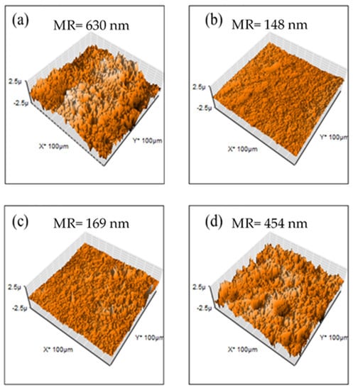
Figure 8.
AFM images for PEI-based membranes: (a) M1, (b) M2, (c) M3 y (d) M4.
Membranes containing Fumion® exhibited a smoother surface (mean roughness ranging between 105 and 345 nm) in comparison with PEI-based membranes (mean roughness ranging between 148 and 630 nm). This is due to better miscibility with those polymers, confirmed SEM images shown before. These membranes have lower surface areas (Figure 9).
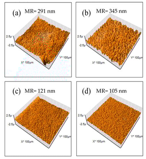
Figure 9.
AFM images for Fumion®-based membranes: (a) F1, (b) F2, (c) F3 y (d) F4.
3.4. Thermogravimetric Analysis (TGA)
The thermal behaviour of membranes was studied by TGA. All the membranes exhibited excellent thermal stability because in the range of 80–150 °C (typical operation range of AEMFC) there was no presence of any degradation step. This is an effect of PVDF, which is a very stable polymer as reported by Lai et al. [50] Figure 10a shows that membranes containing PEI have three important loss stages. The first one at 190 °C is because of the loss of amine groups [51] and the second and third steps are due to degradation of backbone polymers at approximately 500 °C. It is difficult to elucidate which corresponds to each polymer due to the fact that both PES and PVDF degrade at temperatures above 500 °C. In a derivative plot it was observed that a higher quantity of PEI or Fumion® this peak was more evident, which is clear evidence that M1 and F1 have higher values for the amine group.
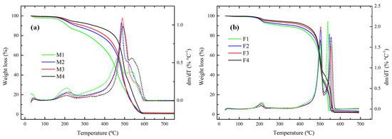
Figure 10.
Thermograms for membranes containing: (a) PEI and (b) Fumion® in N2 atmosphere and heating rate of 20 °C min−1.
3.5. Water Uptake, Swelling Ratio, Ion Exchange Capacity and Hydroxide Conductivity
Water uptake and swelling ratio are shown in Figure 11. For PEI-based membranes the ability for water uptake is remarkable. That is a useful characteristic because membranes must be moist for amines to make hydrogen bonds. Other membranes, such as M1, M3, and M4, exhibited a low swelling ratio. Fumion®-based membranes showed lower water uptake in comparison with PEI membranes and exhibited lower physical deformation.
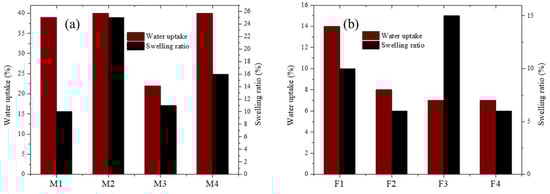
Figure 11.
Swelling ratio and water uptake for membranes containing: (a) PEI and (b) Fumion®.
IEC and hydroxide conductivity values are shown in Table 3. Membranes with a higher PEI/Fumion® content showed higher IEC values (milliequivalents per unit mass). Hydroxide conductivity had a different trend depending on the membrane series. Membranes with a higher content of Fumion® had higher conductivities. Membrane M1 (6 wt% of PEI) showed the highest value of conductivity, but an inversed trend was observed for membranes M2. M3 and M4, increasing the conductivity when the content or PEI decreased in polymeric solution. This trend can be related to the morphological properties of membranes. M4 had higher porosity, which could favour hydroxide conductivity.
Table 3.
IEC and hydroxide conductivity values for PEI/Fumion® membranes.
3.6. Hydroxide Ions Exchange Rate (HIER)
The results of HIER are shown in Figure 12. As shown in Figure 12a, when ratio PEI increases a higher pH value was reached, which is consistent with the quantitative value of hydroxide conductivity due to PEI content. Moreover, M2-M3 showed a similar value of pH, which is in accordance with surface charge density. Regarding analysis of HIER behaviour for short times, M2 reached equilibrium rapidly compared to M4, which can be related to the internal resistance of the membranes to mass and charge transference. For membranes with Fumion®, F1 reached a higher pH value compared toF2–F4, but this occurred at a slow rate. For these membranes, F2 had a faster HIER compared with F1, although the latter had higher concentration of ionomer polymer. Figure 12b shows that M4 and F4 have lower pH values.
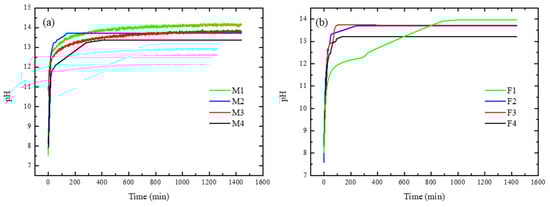
Figure 12.
Hydroxide ions exchange rate for membranes containing: (a) PEI and (b) Fumion®.
Figure 13 shows the behavior of HIER for the first 60 min. Different slopes can be observed, which implies different internal resistances of each membrane due to their internal chemical composition, as their morphology and can influence the real performance of the materials because it determines the transference rate of mass and charge across the membranes, among other phenomena.
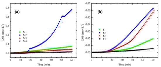
Figure 13.
HIER for first 60 min of process for: (a) PEI and (b) Fumion®.
Table 4 shows the HIER values. Two PEI-synthesized membranes showed a higher value compared to Fumion® membranes, which demonstrates the effect of several parameters of membranes that play very important roles.
Table 4.
Values of hydroxide ion exchange rate.
When ion diffusion phenomena are involved in the membrane, its internal morphology is influenced so that the concentration difference between both compartments is the driving force during the ion exchange phenomenon. In addition, the intrinsic resistance of the membrane to ion transfer is affected. The observed value was higher in the membranes of M1 and M3 which have good WU, IEC and σ, favoring higher rates of anion exchange. Porosity of membranes, morphology and the internal chemical availability of hydroxide ion-conducting groups are the main factors affecting these materials.
3.7. Oxidative Stability
Figure 14a,b shows the stability of PVDF/PES/PEI and PVDF/PES/Fumion® membranes under oxidative stress. It is important to point out that the membranes with the highest ionomer loading (M1 and F1 for PEI and Fumion®, respectively) showed low oxidative stability, since there was a 67% and 88% of residual weight. Even though there was no observation of membrane dissolution; the handling of these membranes was not possible, since the manipulation produced cracking of the membrane. This result was expected because (i) lack of PES in the blend produced a weaker structure in the membrane and/or (ii) the hydrophilic nature of the PEI or Fumion® restricted the attack of free radicals in these domains [58]. Another interesting fact is that the weakening effect of the structure was associated with weight loss, which was more evident for the PVDF/PES/PEI membrane series than for the PVDF/PES/Fumion® membrane series, because Fumion® possesses a polyaromatic backbone that is more stable than the aliphatic structure of the PEI [41].
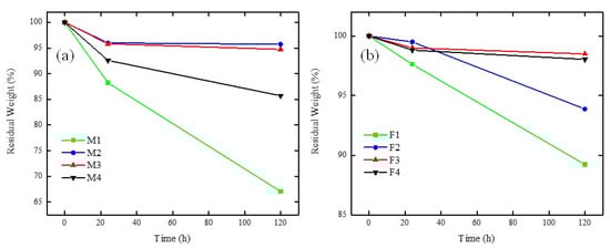
Figure 14.
Oxidative stability for membranes containing: (a) PEI and (b) Fumion® in Fenton reagent at 50 °C.
The membranes containing PVDF/PES/PEI had residual weights from 85–96%, where with increasing PES caused a weakening in the structure. This can be explained based on the disaggregation of the polymers in the blend with higher PES content, while a PES content of 1–2% presented practically the same stability (M2 and M3). This disaggregation phenomenon in PVDF/PES/PEI membranes is in accord with the SEM images (Figure 3), showing that poor miscibility between PVDF and PEI producing sponge structure membranes.
On the other hand, either lower disaggregation or no disaggregation was observed in PVDF/PES/Fumion® blends, since the residual weights ranged from 94–97%. The observed trend followed the increasing order of PES content and stability, where F3 and F4 showed similar behaviour.
4. Conclusions
The preparation of blended membranes by the solvent evaporation method with different chemical compositions (PVDF/PES/PEI and PVDF/PES/Fumion®) is reported in this work. These membranes were characterized by ex situ tests to determine their feasibility as possible alternatives for AEMFC application. The polymers used in the blend, and their nature, determined the performance of blended membranes. Incorporating PEI and Fumion® provided OH- conductivity, and decreasing the quantity of Fumion® reduces membrane cost in comparison to high-cost polymeric membranes. Viscosity changes were a very important factor to consider in the preparation to reduce defects during polymeric-film distribution depending on the polymeric blend. FTIR and EDS analyses confirmed the presence of the different functional groups and characteristic elements such as S, N and F associated with the polymers used to prepare the membranes. Despite having a similar composition, these membranes differed in surface morphologies, where the preparation method and type of ionomer (PEI or Fumion®) played an important role.
According to AFM and SEM images, PEI membranes displayed a rough surface attributed to the apparent incompatibility of PEI with PES. These membranes featured a high swelling ratio and water uptake, and the capability of generating a large amount of hydrogen bonds, which is important properties for ionic transport across the membrane, but counterproductive for the membrane’s mechanical and/or thermal stability, establishing thermal decomposition of amino groups at 180 °C.
HIER, determined by a lab-made cell, is a parameter that may lead to establishing interesting ion transport phenomena through the membrane. This is a remarkable feature in AEMFC application and is dismissed in most of related work. It is associated with different parameters involved in anion exchange through the membrane that are not discussed in this paper. Considering performance and cost, membranes M1 and M3 emerged as excellent options for potential applications in AEMFCs, compared to Fumion®-based and commercial Fumapem®-based membranes.
Supplementary Materials
The following supporting information can be downloaded at: https://www.mdpi.com/article/10.3390/membranes12100959/s1, Figure S1: SEM images of cross section of PEI-based membranes; Figure S2: SEM images of cross section of Fumion®-based membranes.
Author Contributions
Conceptualization, S.P.-S. and M.I.S.-G.; methodology, S.P.-S. and L.J.S.-G.; software, L.J.S.-G.; validation, A.Z.-L., J.C.C.-Y., S.W.L. and T.R.-C.; formal analysis, S.P.-S. and M.I.S.-G.; investigation, S.P.-S., M.I.S.-G., L.J.S.-G. and B.Y.G.-L.; resources, S.P.-S. and M.I.S.-G.; data curation, L.J.S.-G., M.I.S.-G. and S.P.-S.; writing-original draft preparation, L.J.S.-G., M.I.S.-G. and S.P.-S.; writing-review and editing, J.C.C.-Y. and S.W.L.; visualization, S.P.-S. and M.I.S.-G.; supervision, S.P.-S., M.I.S.-G. and T.R.-C.; project administration, S.P.-S. and M.I.S.-G.; funding acquisition, S.P.-S. and M.I.S.-G. All authors have read and agreed to the published version of the manuscript.
Funding
This research was funded by Tecnologico Nacional de Mexico, grant number 9740.20-P and 9829.20-P.
Data Availability Statement
Data is contained within the article.
Acknowledgments
The authors would like to take this opportunity to thank Tecnológico Nacional de México (TecNM) for supporting this research through projects 9740.20-P and 9829.20-P. L. J. Salazar-Gastélum and B. Y. García-Limón appreciate the support by the Consejo Nacional de Ciencia y Tecnología (CONACyT) for scholarships. The authors acknowledge Eng. Jose E. Tirado-Lopez for his comments on improving the manuscript.
Conflicts of Interest
The authors declare no conflict of interest.
References
- Owusu, P.A.; Asumadu-Sarkodie, S. A Review of Renewable Energy Sources, Sustainability Issues and Climate Change Mitigation. Cogent Eng. 2016, 3, 1167990. [Google Scholar] [CrossRef]
- Abbasi, T.; Premalatha, M.; Abbasi, S.A. The Return to Renewables: Will It Help in Global Warming Control? Renew. Sustain. Energy Rev. 2011, 15, 891–894. [Google Scholar] [CrossRef]
- Peterson, T.C.; Connolley, W.M.; Fleck, J. The Myth of the 1970s Global Cooling Scientific Consensus. Bull. Am. Meteorol. Soc. 2008, 89, 1325–1337. [Google Scholar] [CrossRef]
- Yang, Z.; Zhang, J.; Kintner-Meyer, M.C.W.; Lu, X.; Choi, D.; Lemmon, J.P.; Liu, J. Electrochemical Energy Storage for Green Grid. Chem. Rev. 2011, 111, 3577–3613. [Google Scholar] [CrossRef] [PubMed]
- Sun, C.; Negro, E.; Vezzù, K.; Pagot, G.; Cavinato, G.; Nale, A.; Herve Bang, Y.; Di Noto, V. Hybrid Inorganic-Organic Proton-Conducting Membranes Based on SPEEK Doped with WO3 Nanoparticles for Application in Vanadium Redox Flow Batteries. Electrochim. Acta 2019, 309, 311–325. [Google Scholar] [CrossRef]
- Worighi, I.; Maach, A.; Hafid, A.; Hegazy, O.; Van Mierlo, J. Integrating Renewable Energy in Smart Grid System: Architecture, Virtualization and Analysis. Sustain. Energy Grids Netw. 2019, 18, 100226. [Google Scholar] [CrossRef]
- Razmjoo, A.; Gakenia Kaigutha, L.; Vaziri Rad, M.A.; Marzband, M.; Davarpanah, A.; Denai, M. A Technical Analysis Investigating Energy Sustainability Utilizing Reliable Renewable Energy Sources to Reduce CO2 Emissions in a High Potential Area. Renew. Energy 2021, 164, 46–57. [Google Scholar] [CrossRef]
- Sinsel, S.R.; Riemke, R.L.; Hoffmann, V.H. Challenges and Solution Technologies for the Integration of Variable Renewable Energy Sources—A Review. Renew. Energy 2020, 145, 2271–2285. [Google Scholar] [CrossRef]
- Ketter, W.; Collins, J.; Saar-Tsechansky, M.; Marom, O. Information Systems for a Smart Electricity Grid. ACM Trans. Manag. Inf. Syst. 2018, 9, 1–22. [Google Scholar] [CrossRef]
- Vidal-Amaro, J.J.; Østergaard, P.A.; Sheinbaum-Pardo, C. Optimal Energy Mix for Transitioning from Fossil Fuels to Renewable Energy Sources—The Case of the Mexican Electricity System. Appl. Energy 2015, 150, 80–96. [Google Scholar] [CrossRef]
- Ellabban, O.; Abu-Rub, H.; Blaabjerg, F. Renewable Energy Resources: Current Status, Future Prospects and Their Enabling Technology. Renew. Sustain. Energy Rev. 2014, 39, 748–764. [Google Scholar] [CrossRef]
- Chen, H.; Cong, T.N.; Yang, W.; Tan, C.; Li, Y.; Ding, Y. Progress in Electrical Energy Storage System: A Critical Review. Prog. Nat. Sci. 2009, 19, 291–312. [Google Scholar] [CrossRef]
- Vazquez, S.; Lukic, S.; Galvan, E.; Franquelo, L.; Carrasco, J.; Leon, J. Recent Advances on Energy Storage Systems. In Proceedings of the IECON 2011—37th Annual Conference of the IEEE Industrial Electronics, Melbourne, VIC, Australia, 7–10 November 2011; IEEE: New York, NY, USA, 2012; pp. 4636–4640. [Google Scholar]
- Ibrahim, H.; Ilinca, A.; Perron, J. Energy Storage Systems-Characteristics and Comparisons. Renew. Sustain. Energy Rev. 2008, 12, 1221–1250. [Google Scholar] [CrossRef]
- Wang, Y.-J.; Qiao, J.; Baker, R.; Zhang, J. Alkaline Polymer Electrolyte Membranes for Fuel Cell Applications. Chem. Soc. Rev. 2013, 42, 5768–5786. [Google Scholar] [CrossRef]
- Merle, G.; Wessling, M.; Nijmeijer, K. Anion Exchange Membranes for Alkaline Fuel Cells: A Review. J. Memb. Sci. 2011, 377, 1–35. [Google Scholar] [CrossRef]
- Brouzgou, A.; Podias, A.; Tsiakaras, P. PEMFCs and AEMFCs Directly Fed with Ethanol: A Current Status Comparative Review. J. Appl. Electrochem. 2013, 43, 119–136. [Google Scholar] [CrossRef]
- Firouzjaie, H.A.; Mustain, W.E. Catalytic Advantages, Challenges, and Priorities in Alkaline Membrane Fuel Cells. ACS Catal. 2020, 10, 225–234. [Google Scholar] [CrossRef]
- Gutru, R.; Turtayeva, Z.; Xu, F.; Maranzana, G.; Vigolo, B.; Desforges, A. A Comprehensive Review on Water Management Strategies and Developments in Anion Exchange Membrane Fuel Cells. Int. J. Hydrogen Energy 2020, 45, 19642–19663. [Google Scholar] [CrossRef]
- Ziv, N.; Mustain, W.E.; Dekel, D.R. The Effect of Ambient Carbon Dioxide on Anion-Exchange Membrane Fuel Cells. ChemSusChem 2018, 11, 1136–1150. [Google Scholar] [CrossRef]
- Das, G.; Choi, J.-H.; Nguyen, P.K.T.; Kim, D.-J.; Yoon, Y.S. Anion Exchange Membranes for Fuel Cell Application: A Review. Polymers 2022, 14, 1197. [Google Scholar] [CrossRef]
- Maurya, S.; Shin, S.-H.; Kim, Y.; Moon, S.-H. A Review on Recent Developments of Anion Exchange Membranes for Fuel Cells and Redox Flow Batteries. RSC Adv. 2015, 5, 37206–37230. [Google Scholar] [CrossRef]
- Iravaninia, M.; Azizi, S.; Rowshanzamir, S. A Comprehensive Study on the Stability and Ion Transport in Cross-Linked Anion Exchange Membranes Based on Polysulfone for Solid Alkaline Fuel Cells. Int. J. Hydrogen Energy 2017, 42, 17229–17241. [Google Scholar] [CrossRef]
- Ran, J.; Wu, L.; He, Y.; Yang, Z.; Wang, Y.; Jiang, C.; Ge, L.; Bakangura, E.; Xu, T. Ion Exchange Membranes: New Developments and Applications. J. Memb. Sci. 2017, 522, 267–291. [Google Scholar] [CrossRef]
- Arges, C.G.; Zhang, L. Anion Exchange Membranes Evolution toward High Hydroxide Ion Conductivity and Alkaline Resiliency. ACS Appl. Energy Mater. 2018, 1, 2991–3012. [Google Scholar] [CrossRef]
- Kirubakaran, A.; Jain, S.; Nema, R.K. A Review on Fuel Cell Technologies and Power Electronic Interface. Renew. Sustain. Energy Rev. 2009, 13, 2430–2440. [Google Scholar] [CrossRef]
- Dekel, D.R. Review of Cell Performance in Anion Exchange Membrane Fuel Cells. J. Power Sources 2018, 375, 158–169. [Google Scholar] [CrossRef]
- Zhiani, M.; Rostami, H.; Majidi, S.; Karami, K. Bis (Dibenzylidene Acetone) Palladium (0) Catalyst for Glycerol Oxidation in Half Cell and in Alkaline Direct Glycerol Fuel Cell. Int. J. Hydrogen Energy 2013, 38, 5435–5441. [Google Scholar] [CrossRef]
- Tanaka, M.; Fukasawa, K.; Nishino, E.; Yamaguchi, S.; Yamada, K.; Tanaka, H.; Bae, B.; Miyatake, K.; Watanabe, M. Anion Conductive Block Poly(Arylene Ether)s: Synthesis, Properties, and Application in Alkaline Fuel Cells. J. Am. Chem. Soc. 2011, 133, 10646–10654. [Google Scholar] [CrossRef]
- Tran, K.; Nguyen, T.Q.; Bartrom, A.M.; Sadiki, A.; Haan, J.L. A Fuel-Flexible Alkaline Direct Liquid Fuel Cell. Fuel Cells 2014, 14, 834–841. [Google Scholar] [CrossRef]
- Zhao, Y.; Setzler, B.P.; Wang, J.; Nash, J.; Wang, T.; Xu, B.; Yan, Y. An Efficient Direct Ammonia Fuel Cell for Affordable Carbon-Neutral Transportation. Joule 2019, 3, 2472–2484. [Google Scholar] [CrossRef]
- Ma, Y.; Ma, C.; Wang, Y.; Wang, K. Advanced Nickel-Based Catalysts for Urea Oxidation Reaction: Challenges and Developments. Catalysts 2022, 12, 337. [Google Scholar] [CrossRef]
- Anaya-Castro, F.d.J.; Beltrán-Gastélum, M.; Morales Soto, O.; Pérez-Sicairos, S.; Lin, S.W.; Trujillo-Navarrete, B.; Paraguay-Delgado, F.; Salazar-Gastélum, L.J.; Romero-Castañón, T.; Reynoso-Soto, E.; et al. Ultra-Low Pt Loading in PtCo Catalysts for the Hydrogen Oxidation Reaction: What Role Do Co Nanoparticles Play? Nanomaterials 2021, 11, 3156. [Google Scholar] [CrossRef]
- Liu, J.; Yao, J.; Chan, K. Fabrication of Porous Polymer Particles with High Anion Exchange Capacity by Amination Reaction in Aqueous Medium. Green Chem. 2006, 11, 386–389. [Google Scholar] [CrossRef]
- Park, H.J.; Lee, S.Y.; Lee, T.K.; Kim, H.-J.; Lee, Y.M. N3-Butyl Imidazolium-Based Anion Exchange Membranes Blended with Poly(Vinyl Alcohol) for Alkaline Water Electrolysis. J. Membr. Sci. 2020, 611, 118355. [Google Scholar] [CrossRef]
- Niu, M.; Zhang, C.; He, G.; Zhang, F.; Wu, X. Pendent Piperidinium-Functionalized Blend Anion Exchange Membrane for Fuel Cell Application. Int. J. Hydrogen Energy 2019, 44, 15482–15493. [Google Scholar] [CrossRef]
- Morandi, C.G.; Peach, R.; Krieg, H.M.; Kerres, J. Novel Morpholinium-Functionalized Anion-Exchange PBI–Polymer Blends. J. Mater. Chem. A 2015, 3, 1110–1120. [Google Scholar] [CrossRef]
- Konovalova, A.; Kim, H.; Kim, S.; Lim, A.; Park, H.S.; Kraglund, M.R.; Aili, D.; Jang, J.H.; Kim, H.-J.; Henkensmeier, D. Blend Membranes of Polybenzimidazole and an Anion Exchange Ionomer (FAA3) for Alkaline Water Electrolysis: Improved Alkaline Stability and Conductivity. J. Membr. Sci. 2018, 564, 653–662. [Google Scholar] [CrossRef]
- Jung, M.; Lee, W.; Noh, C.; Konovalova, A.; Yi, G.S.; Kim, S.; Kwon, Y.; Henkensmeier, D. Blending Polybenzimidazole with an Anion Exchange Polymer Increases the Efficiency of Vanadium Redox Flow Batteries. J. Membr. Sci. 2019, 580, 110–116. [Google Scholar] [CrossRef]
- Msomi, P.; Nonjola, P.; Ndungu, P.; Ramontja, J. Quaternized Poly (2,6 Dimethyl–1,4 Phenylene Oxide)/Polysulfone Blended Anion Exchange Membrane for Alkaline Fuel Cells Application. Mater. Today Proc. 2018, 5, 10496–10504. [Google Scholar] [CrossRef]
- Lee, N.; Duong, D.T.; Kim, D. Cyclic Ammonium Grafted Poly (Arylene Ether Ketone) Hydroxide Ion Exchange Membranes for Alkaline Water Electrolysis with High Chemical Stability and Cell Efficiency. Electrochim. Acta 2018, 271, 150–157. [Google Scholar] [CrossRef]
- Eyal, A.M.; Canari, R. PH Dependence of Carboxylic and Mineral Acid Extraction by Amine-Based Extractants: Effects of PKa, Amine Basicity, and Diluent Properties. Ind. Eng. Chem. Res. 1995, 34, 1789–1798. [Google Scholar] [CrossRef]
- Quiñonez-Angulo, P.; Hutchinson, R.A.; Licea-Claveríe, Á.; Saldívar-Guerra, E.; Zapata-González, I. The Influences of Monomer Structure and Solvent on the Radical Copolymerization of Tertiary Amine and PEGylated Methacrylates. Polym. Chem. 2021, 12, 5289–5302. [Google Scholar] [CrossRef]
- García-Limón, B.Y.; Salazar-Gastélum, M.I.; Lin, S.W.; Calva-Yañez, J.C.; Pérez-Sicairos, S. Preparation and Characterization of PVFD/PES/Nafion® 117 Membranes with Potential Application in Vanadium Redox Flow Batteries. Rev. Mex. Ing. Química 2019, 18, 477–486. [Google Scholar] [CrossRef]
- Villafaña-López, L.; Reyes-valadez, D.M.; González-vargas, O.A. Custom-Made Ion Exchange Membranes at Laboratory Scale for Reverse Electrodialysis. Membranes 2019, 9, 145. [Google Scholar] [CrossRef]
- Kim, J.-D.; Ohira, A.; Nakao, H. Chemically Crosslinked Sulfonated Polyphenylsulfone (CSPPSU) Membranes for PEM Fuel Cells. Membranes 2020, 10, 31. [Google Scholar] [CrossRef]
- Lu, X.; Peng, Y.; Qiu, H.; Liu, X.; Ge, L. Anti-fouling membranes by manipulating surface wettability and their anti-fouling mechanism. Desalination 2017, 413, 127–135. [Google Scholar] [CrossRef]
- Moarefian, A.; Golestani, H.A.; Bahmanpour, H. Removal of amoxicillin from wastewater by self-made Polyethersulfone membrane using nanofiltration. J. Environ. Health Sci. Eng. 2014, 12, 127. [Google Scholar] [CrossRef] [PubMed]
- Ma, Y.; Liu, W.-J.; Zhang, N.; Li, Y.-S.; Jiang, H.; Sheng, G.-P. Polyethylenimine modified biochar adsorbent for hexavalent chromium removal from the aqueous solution. Bioresour. Technol. 2014, 169, 403–408. [Google Scholar] [CrossRef]
- Lai, C.Y.; Groth, A.; Gray, S.; Duke, M. Investigation of the Dispersion of Nanoclays into PVDF for Enhancement of Physical Membrane Properties. Desalin. Water Treat. 2011, 34, 251–256. [Google Scholar] [CrossRef]
- Xu, X.; Song, C.; Andresen, J.M.; Miller, B.G.; Scaroni, A.W. Novel Polyethylenimine-Modified Mesoporous Molecular Sieve of MCM-41 Type as High-Capacity Adsorbent for CO2 Capture. Energy Fuels 2002, 16, 1463–1469. [Google Scholar] [CrossRef]
- Reyes-Aguilera, J.A.; Villafaña-López, L.; Rentería-Martínez, E.C.; Anderson, S.M.; Jaime-Ferrer, J.S. Electrospinning of Polyepychlorhydrin and Polyacrylonitrile Anionic Exchange Membranes for Reverse Electrodialysis. Membranes 2021, 11, 717. [Google Scholar] [CrossRef]
- Kaczur, J.J.; Yang, H.; Liu, Z.; Sajjad, S.D.; Masel, R.I. Carbon Dioxide and Water Electrolysis Using New Alkaline Stable Anion Membranes. Front. Chem. 2018, 6, 263. [Google Scholar] [CrossRef] [PubMed]
- Jheng, L.-C.; Hsu, S.L.-C.; Lin, B.-Y.; Hsu, Y.-L. Quaternized Polybenzimidazoles with Imidazolium Cation Moieties for Anion Exchange Membrane Fuel Cells. J. Membr. Sci. 2014, 460, 160–170. [Google Scholar] [CrossRef]
- Khan, M.I.; Zheng, C.; Mondal, A.N.; Hossain, M.M.; Wu, B.; Emmanuel, K.; Wu, L.; Xu, T. Preparation of Anion Exchange Membranes from BPPO and Dimethylethanolamine for Electrodialysis. Desalination 2017, 402, 10–18. [Google Scholar] [CrossRef]
- Gohil, J.M.; Dutta, K. Structures and Properties of Polymers in Ion Exchange Membranes for Hydrogen Generation by Water Electrolysis. Polym. Adv. Technol. 2021, 32, 4598–4615. [Google Scholar] [CrossRef]
- Oh, B.H.; Kim, A.R.; Yoo, D.J. Profile of Extended Chemical Stability and Mechanical Integrity and High Hydroxide Ion Conductivity of Poly(Ether Imide) Based Membranes for Anion Exchange Membrane Fuel Cells. Int. J. Hydrogen Energy 2019, 44, 4281–4292. [Google Scholar] [CrossRef]
- Zhang, X.; Shi, Q.; Chen, P.; Zhou, J.; Li, S.; Xu, H.; Chen, X.; An, Z. Block Poly(Arylene Ether Sulfone) Copolymers Tethering Aromatic Side-Chain Quaternary Ammonium as Anion Exchange Membranes. Polym. Chem. 2018, 9, 699–711. [Google Scholar] [CrossRef]
Publisher’s Note: MDPI stays neutral with regard to jurisdictional claims in published maps and institutional affiliations. |
© 2022 by the authors. Licensee MDPI, Basel, Switzerland. This article is an open access article distributed under the terms and conditions of the Creative Commons Attribution (CC BY) license (https://creativecommons.org/licenses/by/4.0/).