
Low- and High-Pressure Membrane Separation in the Production of Process Water for Coke Quenching


Abstract

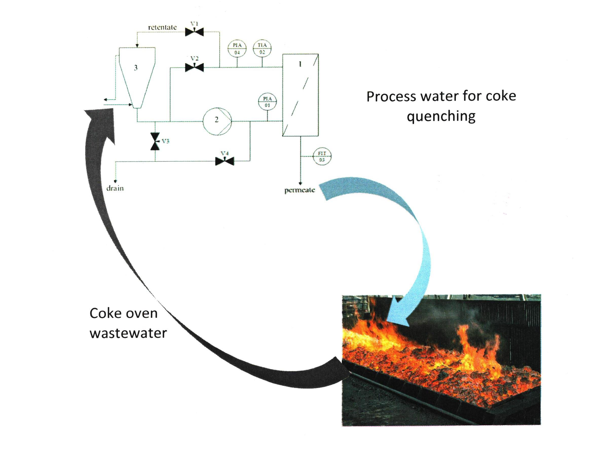
1. Introduction
2. Materials and Methods
2.1. Coke-Oven Wastewater
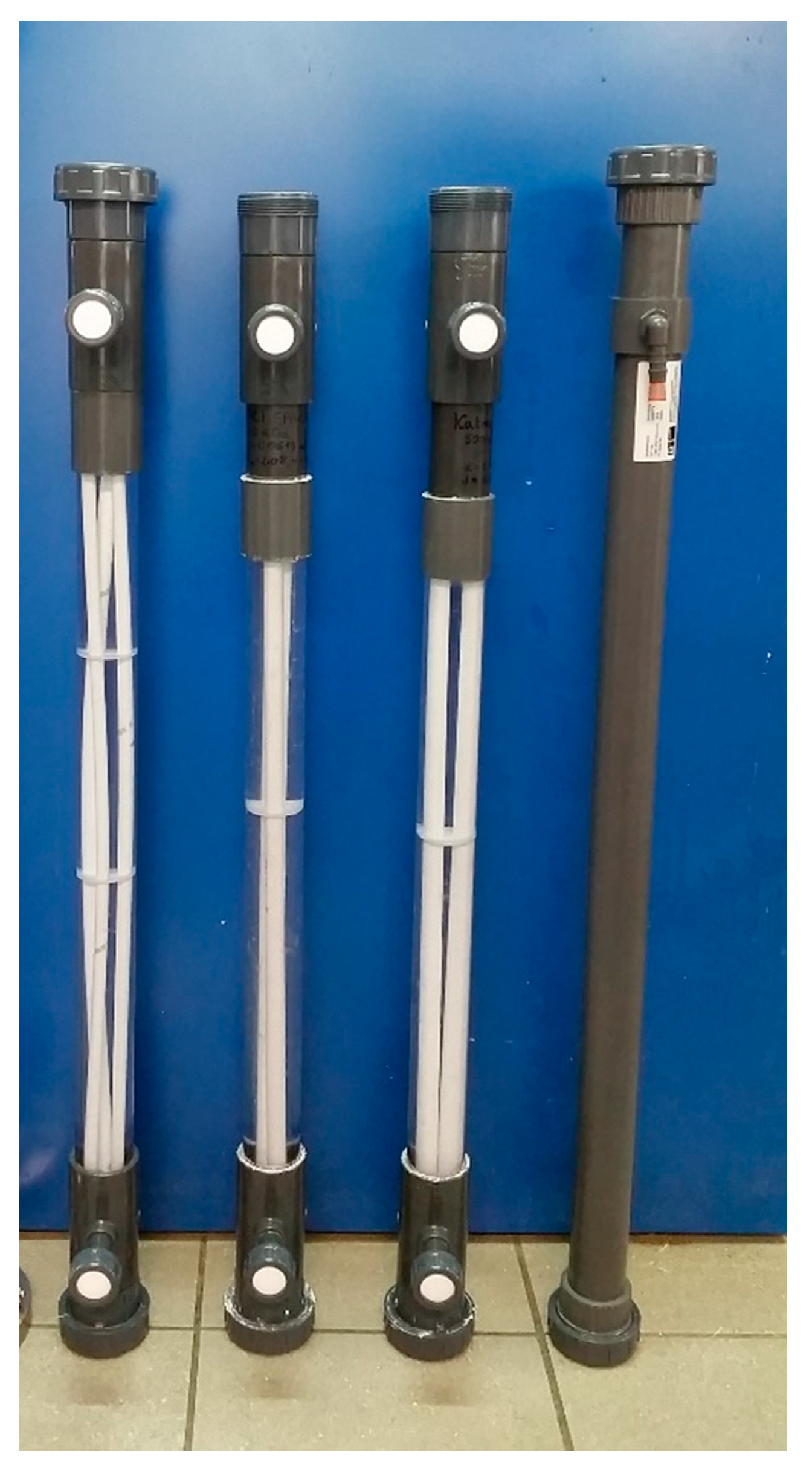
2.2. Membrane Modules and Installations
2.3. Analytical Methods
3. Results
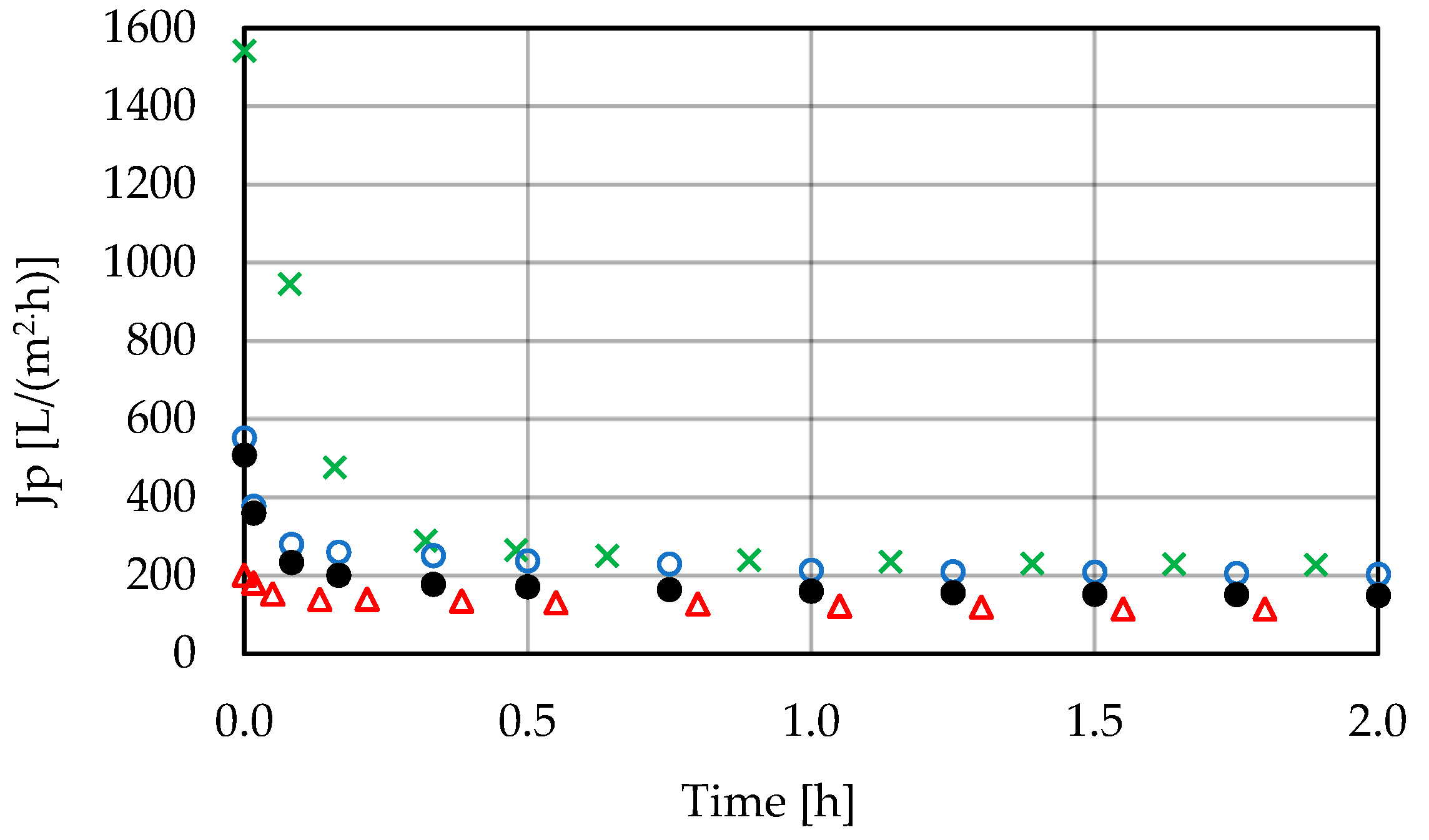
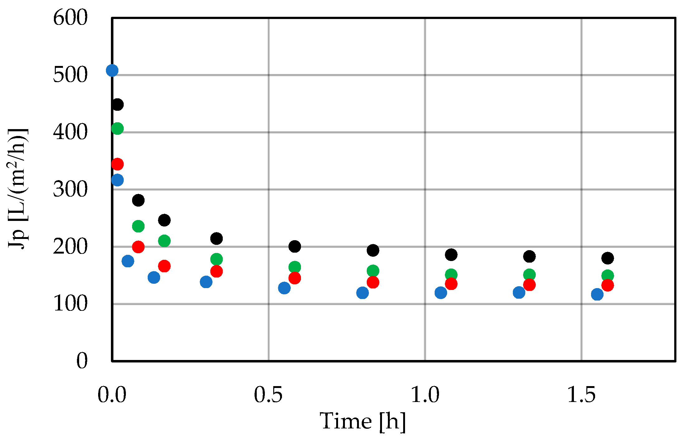
3.1. Low-Pressure Membrane Filtration
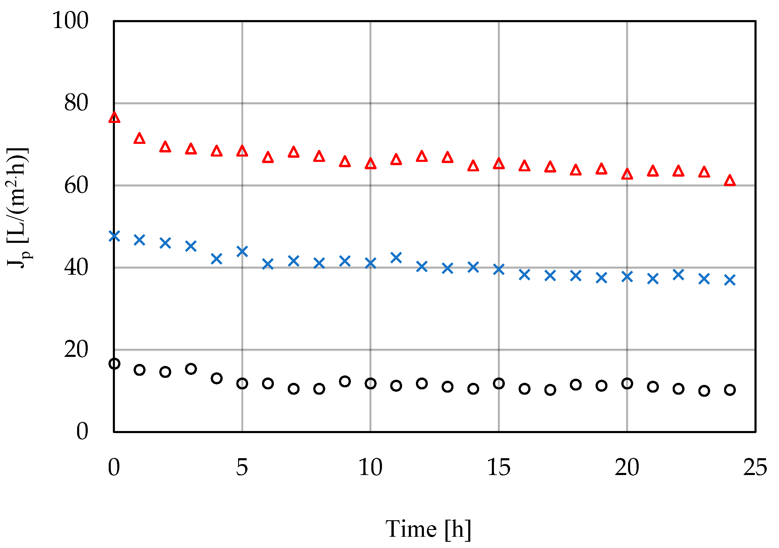
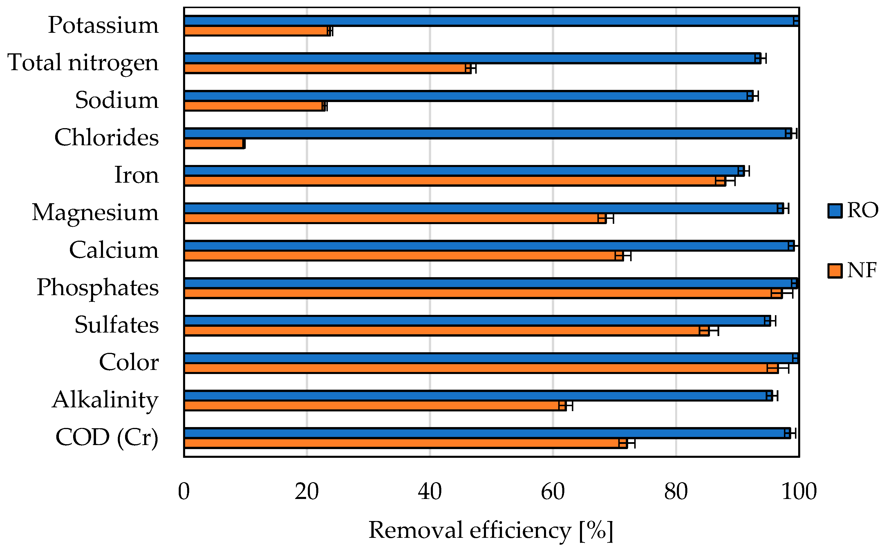
3.2. High-Pressure Membrane Filtration
4. Discussion
5. Conclusions
Supplementary Materials
Author Contributions
Funding
Institutional Review Board Statement
Informed Consent Statement
Data Availability Statement
Conflicts of Interest
References
- Maiti, D.; Ansari, I.; Rather, M.A.; Deepa, A. Comprehensive review on wastewater discharged from the coal-related industries—Characteristics and treatment strategies. Water Sci. Technol. 2019, 79, 2023–2035. [Google Scholar] [CrossRef] [PubMed]
- Mishra, L.; Paul, K.K.; Jena, S. Characterization of coke oven wastewater. In IOP Conference Series—Earth and Environmental Science; Eguchi, K., Quanrud, D., Takagi, H., Eds.; IOP Publishing: Bristol, UK, 2018; Volume 167. [Google Scholar] [CrossRef]
- Rai, A.; Gowrishetty, K.K.; Singh, S.; Chakrabarty, J.; Bhattacharya, P.; Dutta, S. Simultaneous bioremediation of cyanide, phenol, and ammoniacal-N from synthetic coke oven wastewater using Bacillus sp. NITD 19. J. Environ. Eng. 2021, 147, 04020143. [Google Scholar] [CrossRef]
- Elawwad, A.; Naguib, A.; Abdel-Halim, H. Modeling of phenol and cyanide removal in a full-scale coke oven wastewater treatment plant. Desalination Water Treat. 2016, 57, 25181–25193. [Google Scholar] [CrossRef]
- Singh, H.; Mishra, B.K. Degradation of cyanide, aniline and phenol in pre-treated coke oven wastewater by peroxide assisted electro-oxidation process. Water Sci. Technol. 2018, 78, 2214–2227. [Google Scholar] [CrossRef]
- Tyagi, M.; Kumari, N.; Jagadevan, S. A holistic Fenton oxidation-biodegradation system for treatment of phenol from coke oven wastewater: Optimization, toxicity analysis and phylogenetic analysis. J. Water Proc. Eng. 2020, 37, 101475. [Google Scholar] [CrossRef]
- Pillai, I.M.S.; Gupta, A.K. Anodic oxidation of coke oven wastewater: Multiparameter optimization for simultaneous removal of cyanide, COD and phenol. J. Environ. Manag. 2016, 176, 45–53. [Google Scholar] [CrossRef]
- Yngard, R.A.; Sharma, V.K.; Filip, J.; Zboril, R. Ferrate(VI) oxidation of weak-acid dissociable cyanides. Environ. Sci. Technol. 2008, 42, 3005–3010. [Google Scholar] [CrossRef] [PubMed]
- Kwiecinska-Mydlak, A.; Sajdak, M.; Rychlewska, K.; Figa, J. The role of a chemical loop in removal of hazardous contaminants from coke oven wastewater during its treatment. Open Chem. 2019, 17, 1288–1300. [Google Scholar] [CrossRef]
- Maneesh, N.; Bhuvanesh, S.; Shaikh, Z.A.; Sreekrishnan, T.R.; Mazumdar, S.M.; Mitra, C.M. Three-stage biological system for treatment of coke oven effluent. J. Hazard. Toxic Radioact. Waste 2018, 22, 04018012. [Google Scholar] [CrossRef]
- Walter, B.; Haase, C.; Rabiger, N. Combined nitrification/denitrification in a membrane reactor. Water Res. 2005, 39, 2781–2788. [Google Scholar] [CrossRef] [PubMed]
- Best Available Techniques (BAT) Guidelines for the Coking Industry; Ministry of the Environment: Warsaw, Poland, 2005. (In Polish)
- Kwiecinska, A.; Figa, J.; Stelmach, S. The impact of cooling water parameters on the wet-quenched coke quality. Coke Chem. 2014, 57, 425–428. [Google Scholar] [CrossRef]
- Lech, M.; Niesobska, A.; Trusek-Holownia, A. Dairy wastewater utilization:separation of whey proteins in membrane and chromatographic processes. Desalination Water Treat. 2016, 57, 23326–23334. [Google Scholar] [CrossRef]
- Pratofiorito, G.; Horn, H.; Saravia, F. Impact of the recovery on concentrating acetic acid with low-pressure reverse-osmosis membranes. Membranes 2021, 11, 742. [Google Scholar] [CrossRef]
- Trusek-Holownia, A.; Noworyta, A. Two-step of harmful industrial wastewater: An analysis of microbial reactor with integrated membrane retention for benzene and toluene removal. Pol. J. Chem. Technol. 2015, 17, 15–22. [Google Scholar] [CrossRef][Green Version]
- Lee, J.; Na, J.; Baek, Y. Effects of impurities from sugar excipient on filtrate flux during ultrafiltration and diafiltration process. Membranes 2021, 11, 775. [Google Scholar] [CrossRef]
- Kumar, R.; Pal, P. Removal of phenol from coke oven wastewater by Cross-Flow Nanofiltration Membranes. Water Environ. Res. 2013, 85, 447–455. [Google Scholar] [CrossRef] [PubMed]
- Kumar, R.; Pal, P. A novel forward osmosis-nanofiltration integrated system for coke oven wastewater reclamation. Chem. Eng. Res. Design. 2015, 100, 542–553. [Google Scholar] [CrossRef]
- Kwiecinska, A.; Kochel, M.; Rychlewska, K.; Figa, J. The use of ultrafiltration in enhancement of chemical coke oven wastewater treatment. Desalination Water Treat. 2018, 128, 214–221. [Google Scholar] [CrossRef]
- Rychlewska, K.; Kwiecinska, A.; Kochel, K.; Figa, J. The use of polymeric and ceramic ultrafiltration in biologically treated coke oven wastewater polishing. Desalination Water Treat. 2018, 128, 207–213. [Google Scholar] [CrossRef]
- Jin, X.; Li, E.; Lu, S.; Qiu, Z.; Sui, A. Coking wastewater treatment for industrial reuse purpose: Combining biological processes with ultrafiltration, nanofiltration and reverse osmosis. J. Environ. Sci. 2013, 25, 1565–1574. [Google Scholar] [CrossRef]
- Pimple, S.; Karikkat, S.; Devanna, M.; Yanamadni, V.; Sah, R.; Prasad, S.M.R. Comparison of MBR/RO and UF/RO hybrid systems for the treatment of coke-oven effluents. Desalination Water Treat. 2016, 57, 3002–3010. [Google Scholar] [CrossRef]
- Trusek, A.; Wajsprych, M.; Tyrka, M.; Noworyta, A. Regeneration methods of the ultrafiltration membranes applied in coke oven wastewater treatment. Desalination Water Treat. 2021, 214, 120–127. [Google Scholar] [CrossRef]
- Van der Bruggen, B.; Koninckx, A.; Vandecasteele, C. Separation of monovalent and divalent ions from aqueous solution by electrodialysis and nanofiltration. Water Res. 2004, 38, 1347–1353. [Google Scholar] [CrossRef]
- Pérez-González, A.; Ibáñez, R.; Gómez, P.; Urtiaga, A.M.; Ortiz, I.; Irabien, J.A. Nanofiltration separation of polyvalent and monovalent anions in desalination brines. J. Membr. Sci. 2015, 473, 16–27. [Google Scholar] [CrossRef]
- Vaseghi, G.; Ghassemi, A.; Loya, J. Characterization of reverse osmosis and nanofiltration membranes: Effects of operating conditions and specific ion rejection. Desalination Water Treat. 2016, 57, 23461–23472. [Google Scholar] [CrossRef]
- Mao, L.; Tsui, T.-H.; Zhang, J.; Dai, Y.; Tong, Y.W. System integration of hydrothermal liquefaction and anaerobic digestion for wet biomass valorization: Biodegradability and microbial syntrophy. J. Environ. Manag. 2021, 293, 112981. [Google Scholar] [CrossRef]
- Tsui, T.-H.; Wong, J.W.C. A critical review: Emerging bioeconomy and waste-to-energy technologies for sustainable municipal solid waste managent. Waste Dispos. Sustain. Energy 2019, 1, 151–167. [Google Scholar] [CrossRef]
- Ram, C.; Kumar, A.; Rani, P. Municipal solid waste management: A review of waste to energy (WtE) Approaches. Bioresources 2021, 16, 4275–4320. [Google Scholar] [CrossRef]
- Jackowski, M.; Niedzwiecki, L.; Jagiello, K.; Uchanska, O.; Trusek, A. Brewer’s spent grains-valuable beer industry by-product. Biomolecules 2020, 10, 1669. [Google Scholar] [CrossRef]
- Cheng, C.; Zhu, R.; Thompson, R.G.; Zhang, L.H. Reliability analysis for multiple-stage solid waste management systems. Waste Manag. 2021, 120, 650–658. [Google Scholar] [CrossRef]


| Parameter | Raw Wastewater (mg/L) | After Treatment (mg/L) |
|---|---|---|
| COD | 6446 | <250 |
| Phenols | 1656 | <0.1 |
| Ammonium | 4349 | <10 |
| Complex cyanides | 20 | <5 |
| Thiocyanates | 401 | <10 |
| Salinity | 7946 | <5623 |
| Sulfides | 67 | <0.1 |
| Parameter | Unit | Range | Mean Value |
|---|---|---|---|
| pH | pH | 8.2–8.5 | 8.4 |
| Conductivity | mS/cm | 11.3–12.1 | 11.7 |
| Total nitrogen | mg N/L | 50.5 | 50.5 |
| Organic nitrogen | mg Norg/L | 6.4 | 6.4 |
| Ammonia | mg NNH4/L | 0.7–32.7 | 16.7 |
| Nitrate | mg NNO3/L | 10.6–25.4 | 18.0 |
| Nitrite | mg NNO2/L | 0.8 | 0.8 |
| Phosphates | mg P/L | 4.1 | 4.1 |
| Total phosphorus | mg P/L | 4.2 | 4.2 |
| Oxygen dissolved | mg O2/L | 8.9 | 8.9 |
| BOD | mg O2/L | 8.3 | 8.3 |
| COD (Mn) | mg O2/L | 165.8 | 165.8 |
| COD (Cr) | mg O2/L | 398–795 | 617 |
| Total hardness | mg CaCO3/L | 339.3–857 | 598.1 |
| Alkalinity | mg CaCO3/L | 550–700 | 625 |
| Turbidity | NTU | 4.7–34.5 | 17.3 |
| Sulfates | mg SO4/L | 1663–1780.5 | 1721.8 |
| Chlorides | mg Cl/L | 3463–5150 | 4306.5 |
| Sodium | mg Na/L | 200.4–233.7 | 217.0 |
| Potassium | mg K/L | 8.9–11.6 | 10.3 |
| Calcium | mg Ca/L | 28–78.7 | 53.4 |
| Magnesium | mg Mg/L | 5.6–17.2 | 11.4 |
| Manganese | mg Mn/L | 0.1 | 0.1 |
| Iron | mg Fe/L | 1.9–5.1 | 3.5 |
| Color | mg/L | 300–1560 | 930 |
| Total dry matter | mg/L | 7730 | 7730 |
| Mineral dry matter | mg/L | 480 | 480 |
| Organic dry matter | mg/L | 7250 | 7250 |
| TDS | mg/L | 7540 | 7540 |
| Mineral TDS | mg/L | 365 | 365 |
| Organic TDS | mg/L | 7175 | 7175 |
| Total suspension | mg/L | 190 | 190 |
| Mineral suspension | mg/L | 115 | 115 |
| Organic suspension | mg/L | 75 | 75 |
| No | Type | Producer | Material | Selectivity | Diameter (mm) | Length (mm) | No of Tubes | Area (m2) | Cross-Section Area (m2) |
|---|---|---|---|---|---|---|---|---|---|
| 1 | UF | Burkert CUT Ingelfingenm, Germany | PES | 50 kDa | 8.0 | 795 | 3 | 0.059 | 5.03 × 10⁻⁵ |
| 2 | UF | PCI Hampshire, UK | PVDF | 20 kDa | 12.5 | 795 | 2 | 0.062 | 1.23 × 10⁻⁴ |
| 3 | UF | Katmaj, Herford, Germany | PVDF | 500 kDa | 12.5 | 795 | 2 | 0.062 | 1.23 × 10⁻⁴ |
| 4 | UF | Berghof, Leeuwarden, The Netherlands | PVDF | 0.03 μm | 8.0 | 950 | 13 | 0.310 | 5.03 × 10⁻⁵ |
| 5 | NF | PCI Hampshire, UK | PA | 75% CaCl2 | 12.5 | 300 | 2 | 0.024 | 1.23 × 10⁻⁴ |
| 6 | RO | PCI Hampshire, UK | PA | 99% NaCl | 12.5 | 300 | 2 | 0.024 | 1.23 × 10⁻⁴ |
| No | Type | Producer | Material | pH Range | Maximum Temperature (°C) | Maximum Pressure (MPa) |
|---|---|---|---|---|---|---|
| 1 | UF | Burkert CUT | PES | 2–11 | 50 | 0.7 |
| 2 | UF | PCI | PVDF | 1.5–10.5 | 60 | 0.7 |
| 3 | UF | Katmaj | PVDF | 1.5–10.5 | 90 | 1.0 |
| 4 | UF | Berghof | PVDF | 2–10 | 40 | 0.6 |
| 5 | NF | PCI | PA | 1.5–9.5 | 60 | 6.0 |
| 6 | RO | PCI | PA | 1.5–12 | 80 | 6.4 |
| Parameter | Kind of Method | Procedure | Equipment |
|---|---|---|---|
| COD | Titration method | PN-ISO 6060:2006 | Titrator Compact G20S, Mettler Toledo |
| Turbidity | Nephelometric method | PN-EN ISO 7027:2016 | Turbidity Meter TB1000 Thermo Scientific |
| Color | Spectrophotometric method | PN-EN ISO 7887:2002 | Spectrophotometer UV-1800 Shimadzu |
| Alkalinity | Titration method | PN-EN ISO 9963-1:2001 | Titrator Compact G20S, Mettler Toledo |
| Total nitrogen | Kjedahl method | PN-EN 25663:2001 | Titrator Compact G20S, Mettler Toledo |
| Calcium Iron Magnesium Potassium Sodium | Atomic Absorption Spectrometry | ASA ICE3000 Thermo Scientific | |
| Chlorides | Titration method | PN-ISO 9297:1994 | Titrator Compact G20S, Mettler Toledo |
| Phosphates | Spectrophotometric method | PN-ISO 6878/1:2006 | Spectrophotometer UV-1800 Shimadzu |
| Sulfates | Gravimetric method | PN-ISO 9280:2002 | Analytical balance AS 160.R2 Radwag |
| Parameter | Unit | Berghof 0.03 µm | Katmaj 500 kDa | CUT 50 kDa | PCI 20 kDa | |
|---|---|---|---|---|---|---|
| COD | mg O2/L | Feed | 479 ± 13 | 795 ± 16 | 540 ± 12 | 498 ± 12 |
| Permeate | 289 ± 11 | 578 ± 13 | 367 ± 10 | 384 ± 13 | ||
| % removal | 39.7 ± 2.4 | 27.3 ± 2.3 | 32.0 ± 1.9 | 22.9 ± 2.6 | ||
| Turbidity | NTU | Feed | 32.2 ± 1.41 | 12.6 ± 0.81 | 34.5 ± 2.36 | 18.6 ± 0.74 |
| Permeate | 0.28 ± 0.08 | 0.38 ± 0.07 | 1.15 ± 0.11 | 0.23 ± 0.09 | ||
| % removal | 99.1 ± 0.4 | 97.0 ± 0.48 | 96.7 ± 0.39 | 98.8 ± 0.68 | ||
| Color | mg Pt/L | Feed | 2050 ± 154 | 1560 ± 87 | 300 ± 22 | 1840 ± 102 |
| Permeate | 736 ± 77 | 750 ± 64 | 150 ± 19 | 830 ± 82 | ||
| % removal | 64.1 ± 3.8 | 51.9 ± 3.4 | 50.0 ± 2.7 | 54.9 ± 3.3 | ||
| Iron | mg Fe/L | Feed | 6.22 ± 0.43 | 1.93 ± 0.20 | 5.05 ± 0.36 | 2.7 ± 0.27 |
| Permeate | 0.24 ± 0.04 | 0.150 ± 0.02 | 0.17 ± 0.02 | 0.14 ± 0.01 | ||
| % removal | 96.1 ± 0.54 | 92.2 ± 0.33 | 96.6 ± 0.58 | 94.8 ± 0.81 | ||
| Calcium | mg Ca/L | Feed | 107.1 ± 3.64 | 100.5 ± 4.48 | 78.8 ± 2.33 | 94.7 ± 3.49 |
| Permeate | 100 ± 2.99 | 95.7 ± 3.02 | 68.1 ± 2.14 | 91.6 ± 3.19 | ||
| % removal | 6.6 ± 2.74 | 4.8 ± 2.29 | 13.6 ± 4.28 | 3.3 ± 1.86 |
Publisher’s Note: MDPI stays neutral with regard to jurisdictional claims in published maps and institutional affiliations. |
© 2021 by the authors. Licensee MDPI, Basel, Switzerland. This article is an open access article distributed under the terms and conditions of the Creative Commons Attribution (CC BY) license (https://creativecommons.org/licenses/by/4.0/).
Share and Cite
Trusek, A.; Wajsprych, M.; Noworyta, A. Low- and High-Pressure Membrane Separation in the Production of Process Water for Coke Quenching. Membranes 2021, 11, 937. https://doi.org/10.3390/membranes11120937
Trusek A, Wajsprych M, Noworyta A. Low- and High-Pressure Membrane Separation in the Production of Process Water for Coke Quenching. Membranes. 2021; 11(12):937. https://doi.org/10.3390/membranes11120937
Chicago/Turabian StyleTrusek, Anna, Maciej Wajsprych, and Andrzej Noworyta. 2021. "Low- and High-Pressure Membrane Separation in the Production of Process Water for Coke Quenching" Membranes 11, no. 12: 937. https://doi.org/10.3390/membranes11120937
APA StyleTrusek, A., Wajsprych, M., & Noworyta, A. (2021). Low- and High-Pressure Membrane Separation in the Production of Process Water for Coke Quenching. Membranes, 11(12), 937. https://doi.org/10.3390/membranes11120937