
Effective Parameters on Fabrication and Modification of Braid Hollow Fiber Membranes: A Review


 ,
, 
Abstract
:1. Introduction
2. Effective Fabrication Parameters
2.1. Type of Polymer in a Dope Solution
2.2. The Effect of Polymer Concentration
2.3. Effect of Additives
2.4. Effect of Braid Composition
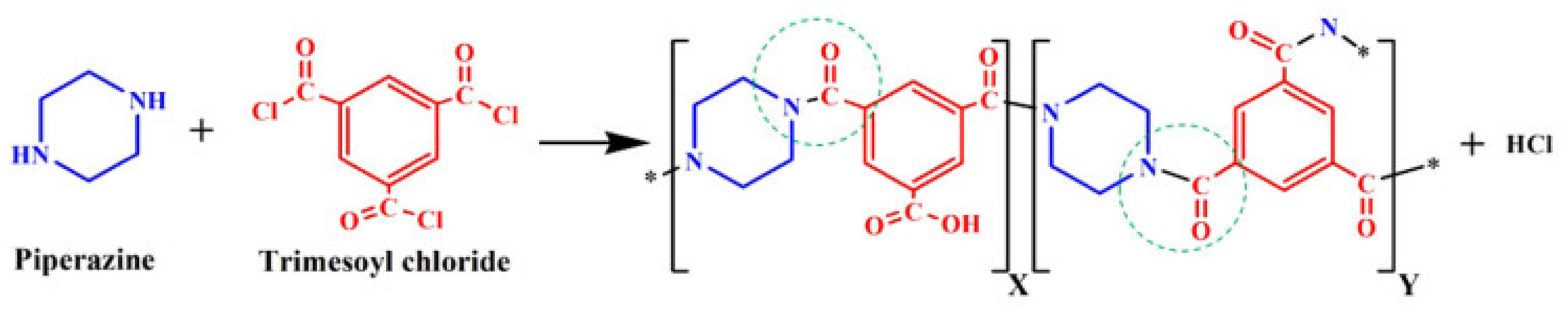
2.5. Thin Film Composite: Braid Hollow Fiber Membranes (TFC-BHFM)
2.5.1. The Effect of Monomer Concentration on TFC-BHFM
2.5.2. Effect of Soaking and Reaction Time in TFC-BHFM Preparation
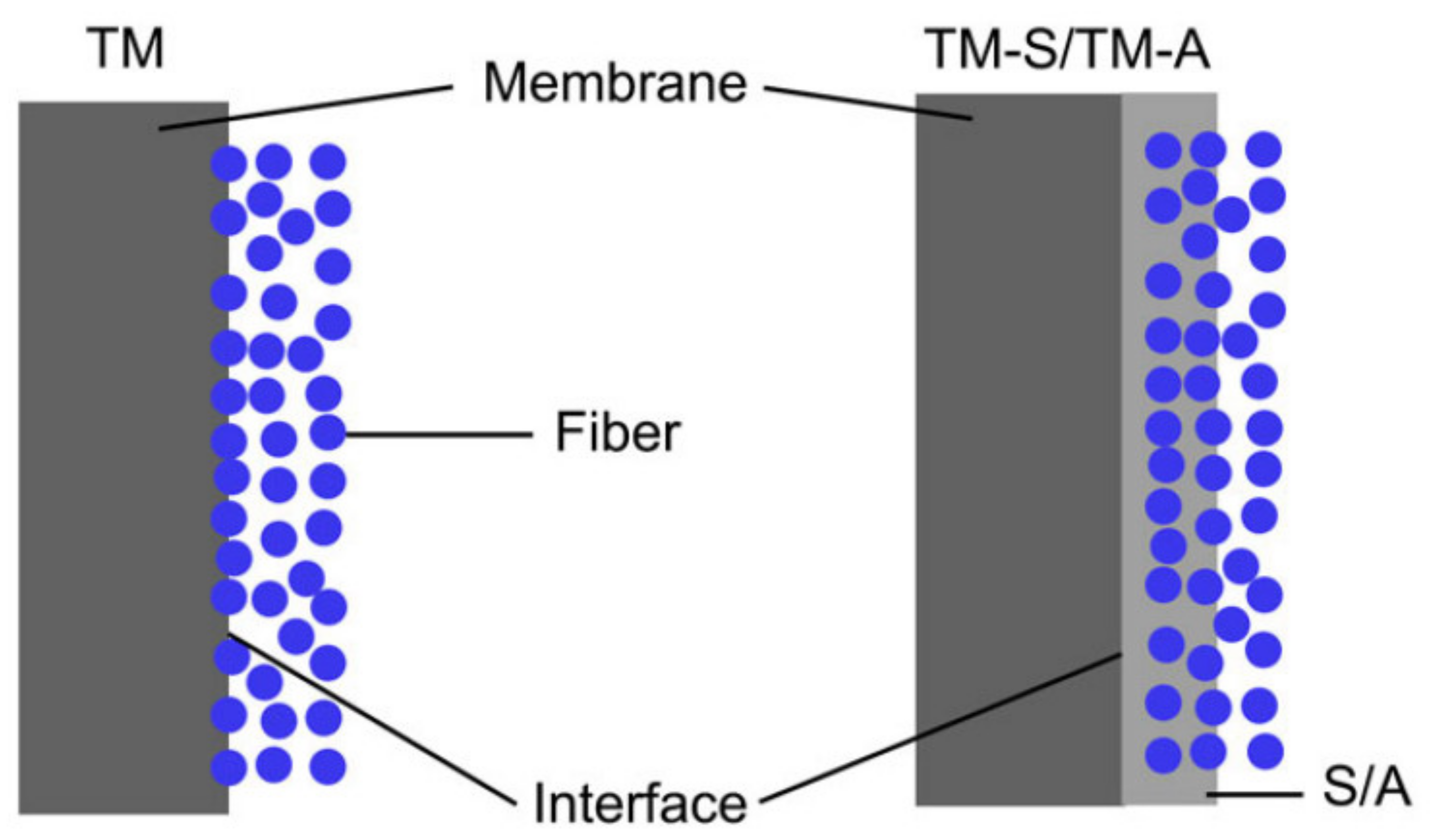
3. Improvement of Interfacial Bonding
3.1. Hybrid Braid Hollow Fiber Membranes
3.2. Alkaline Pretreatment
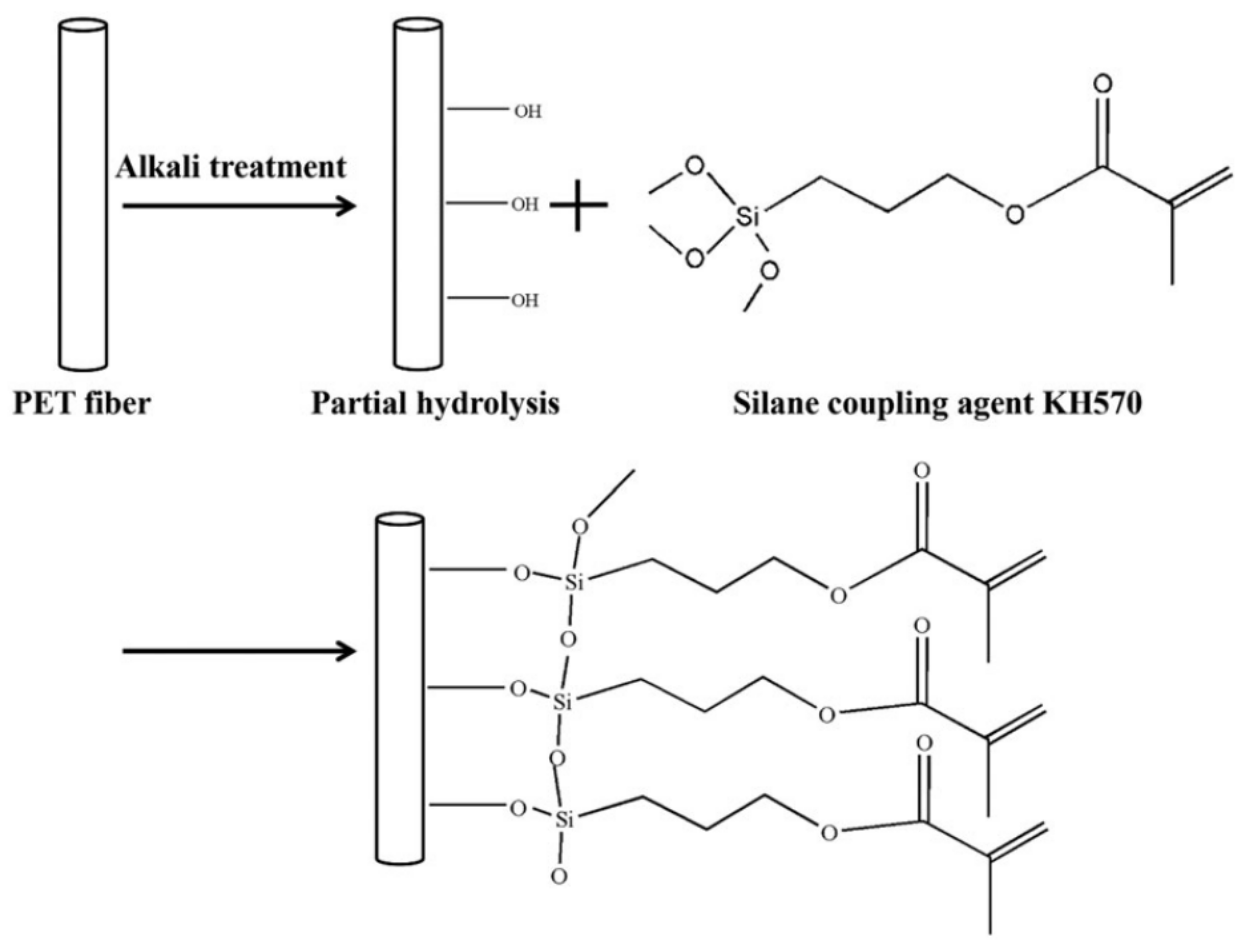
3.3. Modification of the Braid Surface
3.4. The Presence of Additive

| Polymer Coating Solution/wt. (%) Additive in Coating Solution/wt.(%) | Braid (Threads/Filament) Composition | Type of Spinning Methods/ Spinning Conditions | Investigated Parameters | OperationalCondition | Impurities/Application | Results | Comparison with HFM | Ref |
|---|---|---|---|---|---|---|---|---|
| Hybrid braid | ||||||||
| Polymer: CA; 10, 12, 14 (wt.%) Additive: PEG:20 wt.% | CA/PAN | Dry–wet spinning/
|
| Pressure: 0.1 MPa | BSA solution Milk solution | Max Tensile strength (MPa): 33.8 for CA14 and 62.9 MPa for pure PAN in the braid Max BSA Rejection: CA10: 90% CA12: 98% CA14: 99% Max PWF: 300 L/m2h for 1/2 (CA/PAN) Max bursting strength (MPa): 0.75 for pure CA in the braid Min bursting strength (MPa): 0.22 for pure PAN in the braid | NA | [21] |
| Polymer: PVC: 12 wt.% Additive: PVP 10 wt.% | PET/PAN | Dry–wet spinning/
|
| Pressure: 0.1 MPa | BSA solution | Max Tensile strength (MPa): 106 for pure PETMax BSA Rejection: 70% for 1/1: PET/PAN |
| [6] |
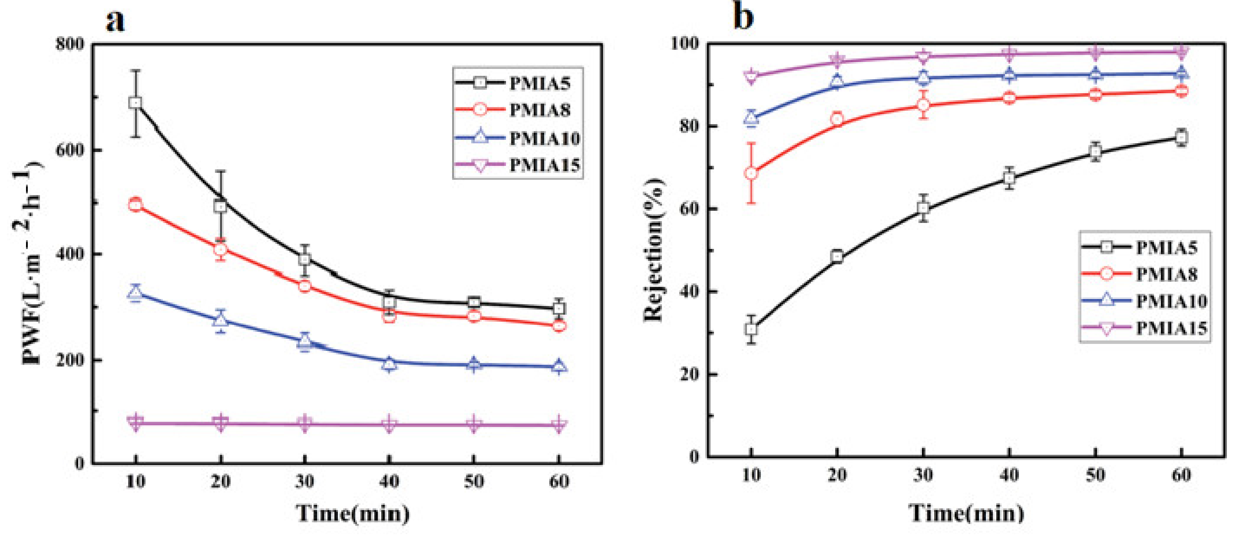
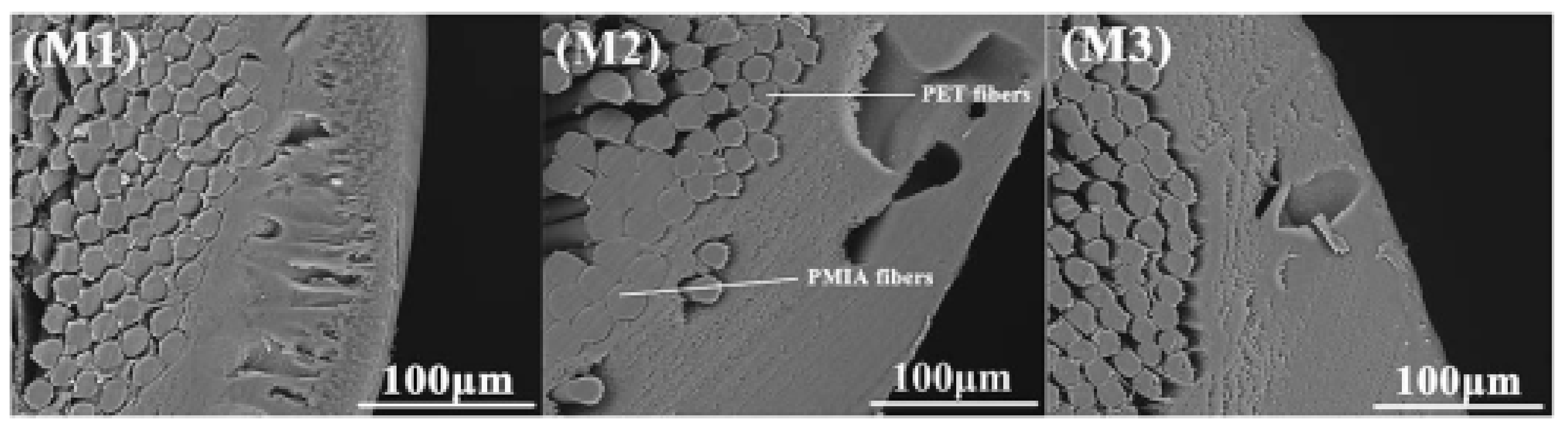
| Polymer: PMIA 5,8,10,15 (wt.%) Additive: PVP 2 wt.%, PEG: 8, CaCl2:3.5, LiCl: 2.5 wt.% | PMIA/PET | Dry–wet spinning/
|
| Pressure: 0.1 MPa | skim milk solution | Max PWF: 296.85 L/m2h for PMIA5 Max BSA Rejection: 97.9% for PMIA15 Max Tensile strength (MPa): 179.15 for PMIA15Max bursting strength (MPa): 0.98 PMIA15 | NA | [28] |
| Polymer: PVDF: 18 wt.% Additive: PEG: 3 wt.% | PVDF- PET | NIPS: Dry–wet spinning/
|
| Pressure: 0.1 MPa | NA | Max PWF: 1388 L/m2h for membrane treat by KOH Max Tensile strength (MPa):113 for membrane treat by KOH | NA | [4] |
| Polymer: PVC 6,8,10,12,14 (wt.%)Additive: PEG 5 | Dry–wet spinning/
|
| NA | Max PWF: 10.1 L/m2h for PVC10 Max BSA Rejection: 76.12% for PVC10 and PEG 6000 |
| [29] | ||
| Pure braid | ||||||||
| Polymer: CA 6,8,10,12,14 (wt.%) Additive: PEG6000:6PEG400:10 | CA | Dry–wet spinning/
|
| Pressure: 0.1 MPa | NA | Max Tensile strength (MPa): 14.2 for CA14 Max bursting strength (MPa): 0.51 for CA14 Max PWF: 220 L/m2h for CA6 Max BSA Rejection: 90% for CA14 | NA | [37] |
| Polymer: PAN 8,10,12,14,16 (wt.%) Additive: PVP (7 wt.%) and Tw-80 (2 wt.%) | PAN | Dry–wet spinning/
|
| Pressure: 0.1 MPa | BSA solution | Tensile strength (MPa): 86.3 Max PWF: 345 L/m2h for PAN10 Max BSA Rejection: 91% for PAN18 | NA | [7] |
| Polymer: PAN 8,10,12,14,16 (wt.%) Additive: PVP (7 wt.%) and Tw-80 (2 wt.%) | PET | Dry–wet spinning/
|
| Pressure: 0.1 MPa | BSA solution | Tensile strength (MPa): 188 Max PWF: 470 L/m2h for PAN10 Max BSA Rejection: 91% for PAN18 | NA | [7] |
| Polymer: PVC Additive: poly(VC-co-PEGMA) | PET | Dry–wet spinning/
| UF BHFM for wastewater treatment |
| [36] | |||
| Polymer: PSf: 16 wt.% Additive: ZnO 0,0.5, 1,1.5 (wt.%) | Dry–wet spinning/
| Pressure: 0.1 MPa | 1000 ppm BSA solution | Max PWF: 920 L/m2h for ZnO:1.5 Max BSA Rejection: 96.5% for ZnO:1.5 |
| [24] | ||
| Polymer: PVDF 15,20,25,30 (wt.%) Additive: PVP20 wt.% PVDF | PET | Dry–wet spinning/ |
| Pressure: 0.1 MPa | Pure water | Max tensile strength (MPa): 11.15 for PVDF20 and 3 PET threads Max PWF: 160 L/m2h for PVDF18 Max bursting strength (MPa): 0.45 PVDF30 |
| [46] |
| Polymer: PVDF 13 (wt.%) Additive: Ge 0,0.1,0.3,0.5,0.7 (wt.%) SiO2:4, DOP:10 | PET | Dry–wet spinning/
|
| 0.1 MPa | kerosene and water mixture (1:1, v/v)/oil/water separation | Max Rejection: 99.7% for Ge:0.5 PWF: 65 L/m2h for GE:0.5 | NA | [38] |
| Polymer: PU 16 wt.% Additive: Ge 0.0.1,0.3,0.5 (wt.%) SA:4, NaCl:0.2 | PET | Electrospinning method/
|
| 0.1 MPa | kerosene and water mixture (1:1, v/v)/oil/water separation | Max Rejection: 99% for Ge:0.3 PWF: 1443 L/m2h for GE:0.3 | NA | [43] |
| Polymer: PVDF 8,10,12,14,16 (wt.%) Additive: PVP:8 (wt.%) Tw-80:2 (wt.%) | PAN | Dry–wet spinning/
| The effect of polymer concentration in coating solutions | Pressure: 0.1 MPa | 1 g/L BSA | Max tensile strength (MPa): 75 Max PWF: 550 L/m2h for PVDF8 Max BSA Rejection: 95% for PVDF16 | NA | [40] |
| Polymer: PVDF 6,8,10,14,18 (wt.%) Additive: PVP:7 (wt.%) Tw-80:3 (wt.%) | PVDF | Dry–wet spinning/
|
| Pressure: 0.1 MPa | 2 g/L Egg albumen | Max tensile strength (MPa):11 for PVDF10 Max PWF: 900 L/m2h for PVDF6 Max BSA Rejection: 81% for PVDF18 |
| [45] |
| Polymer: CA Additive: Ge | - | - |
| - | - | Max tensile strength (MPa):30 Max PWF: 158.1 L/m2h for Ge:1% | NA | [56] |
| Polymer: PA PIP: 2.0% w/v TMC: 0.13% v/v | Polymer: PSf:16 (wt.%) Additive: PVP 10 (wt.%) | Interfacial polymerization of PIP and TMC on UF support membrane |
| Pressure: 0.6 MPa | MgSO4 NaCl TOC/ TFC NF | Max PWF: 5.1 L/m2h MgSO4 Rejection: 65% NaCl Rejection: 26% TOC removal:65% | NA | [51] |
| Polymer: PA PIP: 1.0% w/w TMC:0.1, 0.15, 0.2% w/v | PVDF and polyester | Interfacial polymerization of PIP and TMC on UF support membrane |
| Pressure: 0.1 MPa | MgSO4 NaCl/ TFC NF | Max PWF: 22 L/m2h Max MgSO4 Rejection: 92% NaCl Rejection: ˂30% | NA | [10] |
| Polymer: PVDF | Fiberglass material | - |
| - | - | Max tensile strength (MPa):10 for membrane with 0.355 Thickness | NA | [57] |
4. Operation Parameters
5. Applications
6. Conclusions
Author Contributions
Funding
Institutional Review Board Statement
Informed Consent Statement
Data Availability Statement
Conflicts of Interest
Abbreviations
| HFM: | Hollow fiber membrane |
| BHFM: | Braid Hollow fiber membrane |
| PMIA: | Poly(m-phenylene isophthalamide) |
| PVDF: | Polyvinylidene fluoride |
| Poly(VC-co PEGMA): | Poly(vinyl chloride-co-poly(ethylene glycol) methyl ether methacrylate) |
| NIPS: | Non-solvent-induced phase inversion |
| PA: | Polyamide |
| PET: | Polyethylene terephthalate |
| Ge: | Graphene |
| DOP: | Dioctyl phthalate |
| PU: | Polyurethane |
| SA: | Stearic acid |
| BSA: | Bovine serum albumin |
| PIP: | Piperazine |
| TMC: | Trimesoyl chloride |
| PWF: | Pure water flux |
References
- Al-Maas, M.; Hussain, A.; Matar, J.M.; Ponnamma, D.; Hassan, M.K.; Al-Maadeed, M.A.A.; Alamgir, K.; Adham, S. Validation and application of a membrane filtration evaluation protocol for oil-water separation. J. Water Process. Eng. 2021, 43, 102185. [Google Scholar] [CrossRef]
- Han, R.; Ma, X.; Xie, Y.; Teng, D.; Zhang, S. Preparation of a new 2D MXene/PES composite membrane with excellent hydrophilicity and high flux. RSC Adv. 2017, 7, 56204–56210. [Google Scholar] [CrossRef] [Green Version]
- Li, Q.; Omar, A.; Cha-Umpong, W.; Liu, Q.; Li, X.; Wen, J.; Wang, Y.; Razmjou, A.; Guan, J.; Taylor, R.A. The potential of hollow fiber vacuum multi-effect membrane distillation for brine treatment. Appl. Energy 2020, 276, 115437. [Google Scholar] [CrossRef]
- El-badawy, T.; Othman, M.H.D.; Adam, M.R.; Ismail, A.; Rahman, M.A.; Jaafar, J.; Usman, J.; Mamah, S.C.; Raji, Y.O. The influence of pretreatment step on hollow braided PET fabric as a potential membrane substrate. Mater. Today Proc. 2021, 46, 1990–1997. [Google Scholar] [CrossRef]
- Kim, I.; Choi, D.-C.; Lee, J.; Chae, H.-R.; Jang, J.H.; Lee, C.-H.; Park, P.-K.; Won, Y.-J. Preparation and application of patterned hollow-fiber membranes to membrane bioreactor for wastewater treatment. J. Membr. Sci. 2015, 490, 190–196. [Google Scholar] [CrossRef]
- Liu, H.; Wang, S.; Mao, J.; Xiao, C.; Huang, Q. Preparation and performance of braid-reinforced poly (vinyl chloride) hollow fiber membranes. J. Appl. Polym. Sci. 2017, 134, 45068. [Google Scholar] [CrossRef]
- Quan, Q.; Xiao, C.; Liu, H.; Huang, Q.; Zhao, W.; Hu, X.; Huan, G. Preparation and characterization of braided tube reinforced polyacrylonitrile hollow fiber membranes. J. Appl. Polym. Sci. 2015, 132. [Google Scholar] [CrossRef]
- Wan, C.F.; Yang, T.; Lipscomb, G.G.; Stookey, D.J.; Chung, T.-S. Chapter 11-Design and fabrication of hollow fiber membrane modules. Hollow Fiber Membr. 2021, 225–252. [Google Scholar] [CrossRef]
- Xia, L.; McCutcheon, J. Braided-Reinforced Thin Film Composite (TFC) Nanofiltration Hollow Fiber Membranes. In Proceedings of the 2017 AIChE Annual Meeting, Minneapolis, MN, USA, 1 November 2017. [Google Scholar]
- Xia, L.; Ren, J.; McCutcheon, J.R. Braid-reinforced thin film composite hollow fiber nanofiltration membranes. J. Membr. Sci. 2019, 585, 109–114. [Google Scholar] [CrossRef]
- Zhou, Z.; Fang, L.F.; Wang, S.Y.; Matsuyama, H. Improving bonding strength between a hydrophilic coating layer and poly (ethylene terephthalate) braid for preparing mechanically stable braid-reinforced hollow fiber membranes. J. Appl. Polym. Sci. 2018, 135, 46104. [Google Scholar] [CrossRef]
- Jeon, S.; Karkhanechi, H.; Fang, L.-F.; Cheng, L.; Ono, T.; Nakamura, R.; Matsuyama, H. Novel preparation and fundamental characterization of polyamide 6 self-supporting hollow fiber membranes via thermally induced phase separation (TIPS). J. Membr. Sci. 2018, 546, 1–14. [Google Scholar] [CrossRef]
- Matsuyama, H.; Karkhanechi, H.; Rajabzadeh, S. Polymeric Membrane Fabrication via Thermally Induced Phase Separation (TIPS) Method; Elsevier: Amsterdam, The Netherlands, 2021; Chapter 3. [Google Scholar]
- Wang, K.; Abdala, A.; Hilal, N.; Khraisheh, M. Mechanical characterization of membranes. In Membrane Characterization; Elsevier: Amsterdam, The Netherlands, 2017; pp. 259–306. [Google Scholar]
- Hosseini, S.S.; Nazif, A.; Shahmirzadi, M.A.A.; Ortiz, I. Fabrication, tuning and optimization of poly (acrilonitryle) nanofiltration membranes for effective nickel and chromium removal from electroplating wastewater. Sep. Purif. Technol. 2017, 187, 46–59. [Google Scholar] [CrossRef] [Green Version]
- Hou, D.; Fan, H.; Jiang, Q.; Wang, J.; Zhang, X. Preparation and characterization of PVDF flat-sheet membranes for direct contact membrane distillation. Sep. Purif. Technol. 2014, 135, 211–222. [Google Scholar] [CrossRef]
- Hou, D.; Dai, G.; Fan, H.; Wang, J.; Zhao, C.; Huang, H. Effects of calcium carbonate nano-particles on the properties of PVDF/nonwoven fabric flat-sheet composite membranes for direct contact membrane distillation. Desalin. 2014, 347, 25–33. [Google Scholar] [CrossRef]
- Wei, J.; Qiu, C.; Tang, C.Y.; Wang, R.; Fane, A.G. Synthesis and characterization of flat-sheet thin film composite forward osmosis membranes. J. Membr. Sci. 2011, 372, 292–302. [Google Scholar] [CrossRef]
- Huo, R.; Gu, Z.; Zuo, K.; Zhao, G. Preparation and properties of PVDF-fabric composite membrane for membrane distillation. Desalination 2009, 249, 910–913. [Google Scholar] [CrossRef]
- Dabiryan, H.; Johari, M.; Bakhtiyari, S.; Eskandari, E. Analysis of the tensile behavior of tubular braids using energy method, Part II: Experimental study. J. Text. Inst. 2017, 108, 1899–1904. [Google Scholar] [CrossRef]
- Fan, Z.; Xiao, C.; Liu, H.; Huang, Q.; Zhao, J. Structure design and performance study on braid-reinforced cellulose acetate hollow fiber membranes. J. Membr. Sci. 2015, 486, 248–256. [Google Scholar] [CrossRef]
- Karkhanechi, H.; Rajabzadeh, S.; Di Nicolò, E.; Usuda, H.; Shaikh, A.R.; Matsuyama, H. Preparation and characterization of ECTFE hollow fiber membranes via thermally induced phase separation (TIPS). Polymer 2016, 97, 515–524. [Google Scholar] [CrossRef]
- Mahendran, M.; Goodboy, K.P.; Fabbricino, L. Hollow Fiber Membrane and Braided Tubular Support Therefor. U.S. Patent 6,354,444 B1, 11 March 2002. [Google Scholar]
- Peechmani, P.; Othman, M.H.D.; Kamaludin, R.; Puteh, M.H.; Jaafar, J.; Rahman, M.A.; Ismail, A.F.; Kadir, S.H.S.A.; Illias, R.M.; Gallagher, J. High Flux Polysulfone Braided Hollow Fiber Membrane for Wastewater Treatment Role of Zinc Oxide as Hydrophilic Enhancer. J. Environ. Chem. Eng. 2021, 9, 105873. [Google Scholar] [CrossRef]
- Cooper, W.W.; Shea, E.M. Process for Casting Integrally Supported Tubular Membranes. U.S. Patent 3,676,193, 11 July 1972. [Google Scholar]
- Mailvaganam, M.; Fabbricino, L.; Rodrigues, C.F.; Donnelly, A.R. Hollow Fiber Semipermeable Membrane of Tubular Braid. U.S. Patent 5,472,607, 5 December 1995. [Google Scholar]
- Teoh, M.M.; Bonyadi, S.; Chung, T.-S. Investigation of different hollow fiber module designs for flux enhancement in the membrane distillation process. J. Membr. Sci. 2008, 311, 371–379. [Google Scholar] [CrossRef]
- Chen, M.; Xiao, C.; Wang, C.; Liu, H. Study on the structural design and performance of novel braid-reinforced and thermostable poly (m-phenylene isophthalamide) hollow fiber membranes. RSC Adv. 2017, 7, 20327–20335. [Google Scholar] [CrossRef] [Green Version]
- Liu, H.; Xiao, C.; Huang, Q.; Hu, X. Structure design and performance study on homogeneous-reinforced polyvinyl chloride hollow fiber membranes. Desalination 2013, 331, 35–45. [Google Scholar] [CrossRef]
- Song, L.; Huang, Q.; Huang, Y.; Bi, R.; Xiao, C. An electro-thermal braid-reinforced PVDF hollow fiber membrane for vacuum membrane distillation. J. Membr. Sci. 2019, 591, 117359. [Google Scholar] [CrossRef]
- Aslan, T.; Arslan, S.; Eyvaz, M.; Güçlü, S.; Yüksel, E.; Koyuncu, I. A novel nanofiber microfiltration membrane: Fabrication and characterization of tubular electrospun nanofiber (TuEN) membrane. J. Membr. Sci. 2016, 520, 616–629. [Google Scholar] [CrossRef]
- Frenot, A.; Chronakis, I.S. Polymer nanofibers assembled by electrospinning. Curr. Opin. Colloid Interface Sci. 2003, 8, 64–75. [Google Scholar] [CrossRef]
- Moattari, R.M.; Mohammadi, T.; Rajabzadeh, S.; Dabiryan, H.; Matsuyama, H. Reinforced hollow fiber membranes: A comprehensive review. J. Taiwan Inst. Chem. Eng. 2021, 122, 284–310. [Google Scholar] [CrossRef]
- Turken, T.; Sengur-Tasdemir, R.; Ates-Genceli, E.; Tarabara, V.V.; Koyuncu, I. Progress on reinforced braided hollow fiber membranes in separation technologies: A review. J. Water Process. Eng. 2019, 32, 100938. [Google Scholar] [CrossRef]
- Abba, M.U.; Man, H.C.; Azis, R.S.; Idris, A.I.; Hamzah, M.H.; Yunos, K.F.; Katibi, K.K. Novel PVDF-PVP Hollow Fiber Membrane Augmented with TiO2 Nanoparticles: Preparation, Characterization and Application for Copper Removal from Leachate. Nanomaterials 2021, 11, 399. [Google Scholar] [CrossRef]
- Zhou, Z.; Rajabzadeh, S.; Fang, L.; Miyoshi, T.; Kakihana, Y.; Matsuyama, H. Preparation of robust braid-reinforced poly (vinyl chloride) ultrafiltration hollow fiber membrane with antifouling surface and application to filtration of activated sludge solution. Mater. Sci. Eng. C 2017, 77, 662–671. [Google Scholar] [CrossRef] [PubMed]
- Fan, Z.; Xiao, C.; Liu, H.; Huang, Q. Preparation and performance of homogeneous braid reinforced cellulose acetate hollow fiber membranes. Cellulose 2015, 22, 695–707. [Google Scholar] [CrossRef]
- Hao, J.; Xiao, C.; Zhang, T.; Zhao, J.; Fan, Z.; Chen, L. Preparation and performance of PET-braid-reinforced poly (vinylidene fluoride)/graphene hollow-fiber membranes. Ind. Eng. Chem. Res. 2016, 55, 2174–2182. [Google Scholar] [CrossRef]
- Matsuyama, H.; Rajabzadeh, S.; Karkhanechi, H.; Jeon, S. 1.7 PVDF Hollow Fibers Membranes. In Comprehensive Membrane Science and Engineering; Elsevier: Amsterdam, The Netherlands, 2017; pp. 137–189. [Google Scholar]
- Quan, Q.; Xiao, C.F.; Liu, H.L.; Zhao, W.; Hu, X.Y.; Huan, G.L. Preparation and properties of two-dimensional braid heterogeneous-reinforced polyvinylidene fluoride hollow fiber membrane. In Advanced Materials Research; Trans Tech Publications Ltd.: Freinbach, Switzerland, 2014. [Google Scholar]
- Rajabzadeh, S.; Ogawa, D.; Ohmukai, Y.; Zhou, Z.; Ishigami, T.; Matsuyama, H. Preparation of a PVDF hollow fiber blend membrane via thermally induced phase separation (TIPS) method using new synthesized zwitterionic copolymer. Desalin. Water Treat 2015, 54, 2911–2919. [Google Scholar] [CrossRef]
- Karkhanechi, H.; Vaselbehagh, M.; Jeon, S.; Shaikh, A.R.; Wang, D.-M.; Matsuyama, H. Preparation and characterization of polyvinylidenedifluoride-co-chlorotrifluoroethylene hollow fiber membranes with high alkaline resistance. Polymer 2018, 145, 310–323. [Google Scholar] [CrossRef]
- Wu, Y.-J.; Xiao, C.-F.; Zhao, J. Preparation of an electrospun tubular PU/GE nanofiber membrane for high flux oil/water separation. RSC Adv. 2019, 9, 33722–33732. [Google Scholar] [CrossRef] [Green Version]
- Liu, H.; Xiao, C.; Huang, Q.; Hu, X.; Shu, W. Preparation and interface structure study on dual-layer polyvinyl chloride matrix reinforced hollow fiber membranes. J. Membr. Sci. 2014, 472, 210–221. [Google Scholar] [CrossRef]
- Zhang, X.; Xiao, C.; Hu, X.; Bai, Q. Preparation and properties of homogeneous-reinforced polyvinylidene fluoride hollow fiber membrane. Appl. Surf. Sci. 2013, 264, 801–810. [Google Scholar] [CrossRef]
- Liu, J.; Li, P.; Li, Y.; Xie, L.; Wang, S.; Wang, Z. Preparation of PET threads reinforced PVDF hollow fiber membrane. Desalination 2009, 249, 453–457. [Google Scholar] [CrossRef]
- Lan, S.; Lei, W.; Xudong, W.; Chen, L.; Song, H.; Mingjiao, Y. Hydrophilic modification and properties of TiO2/PVDF woven tubal hollow fiber composite membrane. Chin. J. Environ. Eng. 2016, 10, 4796–4802. [Google Scholar]
- Lee, M.S.; Lee, K.J.; Shin, Y.-C. Braid-Reinforced Composite Hollow Fiber Membrane. U.S. Patent 7,909,177, 22 March 2011. [Google Scholar]
- Lee, M.S.; Lee, K.J.; Shin, Y.-C. Braid-Reinforced Composite Hollow Fiber Membrane. U.S. Patent 8,147,938, 3 April 2012. [Google Scholar]
- Lau, W.; Ismail, A.; Misdan, N.; Kassim, M. A recent progress in thin film composite membrane: A review. Desalination 2012, 287, 190–199. [Google Scholar] [CrossRef] [Green Version]
- Turken, T.; Sengur-Tasdemir, R.; Sayinli, B.; Urper-Bayram, G.M.; Ates-Genceli, E.; Tarabara, V.V.; Koyuncu, I. Reinforced thin-film composite nanofiltration membranes: Fabrication, characterization, and performance testing. J. Appl. Polym. Sci. 2019, 136, 48001. [Google Scholar] [CrossRef]
- Zhang, H.; Zheng, J.; Zhao, Z.; Han, C.C. Role of wettability in interfacial polymerization based on PVDF electrospun nanofibrous scaffolds. J. Membr. Sci. 2013, 442, 124–130. [Google Scholar] [CrossRef]
- Ooi, B.; Sum, J.; Lai, S. Investigation on membrane morphological and chemical properties changes at different reaction times and its effect on dye removal. Desalin. Water Treat. 2012, 45, 250–255. [Google Scholar] [CrossRef]
- Huang, Y.; Xiao, C.; Huang, Q.; Liu, H.; Zhao, J. Progress on polymeric hollow fiber membrane preparation technique from the perspective of green and sustainable development. Chem. Eng. J. 2021, 403, 126295. [Google Scholar] [CrossRef]
- Liu, L.; Shen, H.; Li, T.; Han, Y. Interface treatment and performance study on fiber tube reinforced polyvinylidene fluoride hollow fiber membranes. J. Text. Inst. 2020, 111, 1054–1063. [Google Scholar] [CrossRef]
- Fan, Z.; Xiao, C.; Huang, Q.; Tang, B. Modification of braid-reinforced cellulose acetate hollow fiber membrane by doping graphene oxide. Desalin. Water Treat. 2017, 68, 345–352. [Google Scholar] [CrossRef]
- Park, M.J.; Kim, H. Indirect measurement of tensile strength of hollow fiber braid membranes. Desalination 2008, 234, 107–115. [Google Scholar] [CrossRef]
- Corpuz, M.V.A.; Borea, L.; Senatore, V.; Castrogiovanni, F.; Buonerba, A.; Oliva, G.; Ballesteros, F., Jr.; Zarra, T.; Belgiorno, V.; Choo, K.-H. Wastewater treatment and fouling control in an electro algae-activated sludge membrane bioreactor. Sci. Total Environ. 2021, 786, 147475. [Google Scholar] [CrossRef]
- Li, Q.-M.; Ma, H.-Y.; Hu, Y.-N.; Guo, Y.-F.; Zhu, L.-J.; Zeng, Z.-X.; Wang, G. Polyamide thin-film composite membrane on polyethylene porous membrane: Fabrication, characterization and application in water treatment. Mater. Lett. 2021, 287, 129270. [Google Scholar] [CrossRef]
- Davenport, D.M.; Ritt, C.L.; Verbeke, R.; Dickmann, M.; Egger, W.; Vankelecom, I.F.; Elimelech, M. Thin film composite membrane compaction in high-pressure reverse osmosis. J. Membr. Sci. 2020, 610, 118268. [Google Scholar] [CrossRef]
- Ecker, P.; Pekovits, M.; Yorov, T.; Haddadi, B.; Lukitsch, B.; Elenkov, M.; Janeczek, C.; Jordan, C.; Gfoehler, M.; Harasek, M. Microstructured Hollow Fiber Membranes: Potential Fiber Shapes for Extracorporeal Membrane Oxygenators. Membranes 2021, 11, 374. [Google Scholar] [CrossRef] [PubMed]


| Polymer | Chemical Structure. | Advantages | Disadvantages/Improvement Approach | Application | Ref. |
|---|---|---|---|---|---|
| PAN |  |
|
| Water, municipal, and industrial wastewater treatment | [7,31] |
| PVC | 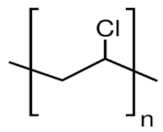 |
|
| Ultrafiltration BHFM for wastewater treatment | [36] |
| PSf |  |
|
| Wastewater treatment | [24] |
| CA | 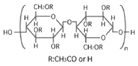 |
|
| Wastewater treatment | [21,37] |
| PVDF | 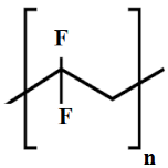 |
| oil/water separation [38] wastewater treatment [30] | [38,39,40,41,42] | |
| PMIA | 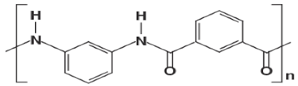 |
| NA | wastewater treatment | [28] |
| PU |  |
| NA | oil/water separation | [43] |
Publisher’s Note: MDPI stays neutral with regard to jurisdictional claims in published maps and institutional affiliations. |
© 2021 by the authors. Licensee MDPI, Basel, Switzerland. This article is an open access article distributed under the terms and conditions of the Creative Commons Attribution (CC BY) license (https://creativecommons.org/licenses/by/4.0/).
Share and Cite
Nazif, A.; Karkhanechi, H.; Saljoughi, E.; Mousavi, S.M.; Matsuyama, H. Effective Parameters on Fabrication and Modification of Braid Hollow Fiber Membranes: A Review. Membranes 2021, 11, 884. https://doi.org/10.3390/membranes11110884
Nazif A, Karkhanechi H, Saljoughi E, Mousavi SM, Matsuyama H. Effective Parameters on Fabrication and Modification of Braid Hollow Fiber Membranes: A Review. Membranes. 2021; 11(11):884. https://doi.org/10.3390/membranes11110884
Chicago/Turabian StyleNazif, Azadeh, Hamed Karkhanechi, Ehsan Saljoughi, Seyed Mahmoud Mousavi, and Hideto Matsuyama. 2021. "Effective Parameters on Fabrication and Modification of Braid Hollow Fiber Membranes: A Review" Membranes 11, no. 11: 884. https://doi.org/10.3390/membranes11110884
APA StyleNazif, A., Karkhanechi, H., Saljoughi, E., Mousavi, S. M., & Matsuyama, H. (2021). Effective Parameters on Fabrication and Modification of Braid Hollow Fiber Membranes: A Review. Membranes, 11(11), 884. https://doi.org/10.3390/membranes11110884