Tuning the Surface Structure of Polyamide Membranes Using Porous Carbon Nitride Nanoparticles for High-Performance Seawater Desalination

 ,
, 
Abstract

1. Introduction
2. Materials and Methods
2.1. Chemicals
2.2. Synthesis of C3N4 Nanoparticles
2.3. Preparation of C3N4 Aqueous Suspension
2.4. Preparation of PSf Porous Supports
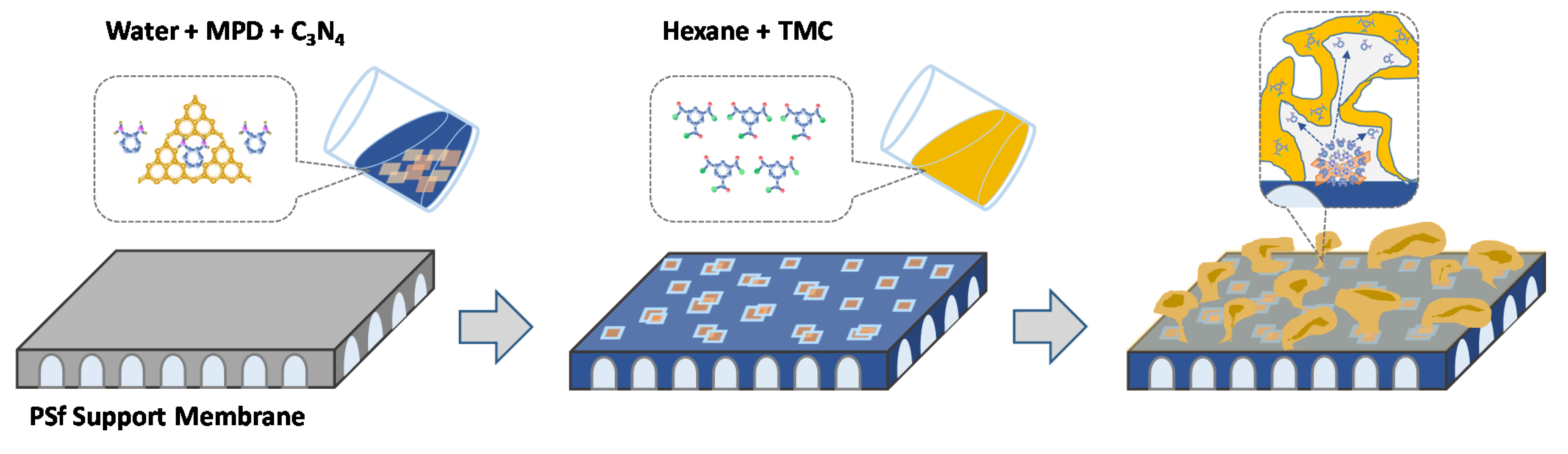
2.5. IP to Prepare PA-TFC Membrane
2.6. IP to Prepare C3N4 TFN Membrane
2.7. Characterization
2.8. Evaluation of RO Desalination Performance
3. Results and Discussion
4. Conclusions
Supplementary Materials
Author Contributions
Funding
Conflicts of Interest
References
- Mekonnen, M.M.; Hoekstra, A.Y. Four billion people facing severe water scarcity. Sci. Adv. 2016, 2, e1500323. [Google Scholar] [CrossRef] [PubMed]
- Hoover, L.A.; Phillip, W.A.; Tiraferri, A.; Yip, N.Y.; Elimelech, M. Forward with osmosis: Emerging applications for greater sustainability. Environ. Sci. Technol. 2011, 45, 9824–9830. [Google Scholar] [CrossRef]
- Kim, B.; Gwak, G.; Hong, S. Review on methodology for determining forward osmosis (FO) membrane characteristics: Water permeability (A), solute permeability (B), and structural parameter (S). Desalination 2017, 422, 5–16. [Google Scholar] [CrossRef]
- Klaysom, C.; Cath, T.Y.; Depuydt, T.; Vankelecom, I.F. Forward and pressure retarded osmosis: Potential solutions for global challenges in energy and water supply. Chem. Soc. Rev. 2013, 42, 6959–6989. [Google Scholar] [CrossRef] [PubMed]
- Shaffer, D.L.; Werber, J.R.; Jaramillo, H.; Lin, S.; Elimelech, M. Forward osmosis: Where are we now? Desalination 2015, 356, 271–284. [Google Scholar] [CrossRef]
- Choi, W.; Gu, J.-E.; Park, S.-H.; Kim, S.; Bang, J.; Baek, K.-Y.; Park, B.; Lee, J.S.; Chan, E.P.; Lee, J.-H. Tailor-Made Polyamide Membranes for Water Desalination. ACS Nano 2015, 9, 345–355. [Google Scholar] [CrossRef]
- Chowdhury, M.R.; Steffes, J.; Huey, B.D.; McCutcheon, J.R. 3D printed polyamide membranes for desalination. Science 2018, 361, 682–686. [Google Scholar] [CrossRef]
- Geise, G.M.; Park, H.B.; Sagle, A.C.; Freeman, B.D.; Mcgrath, J.E. Water permeability and water/salt selectivity tradeoff in polymers for desalination. J. Membr. Sci. 2011, 369, 130–138. [Google Scholar] [CrossRef]
- Jeong, B.-H.; Hoek, E.M.; Yan, Y.; Subramani, A.; Huang, X.; Hurwitz, G.; Ghosh, A.K.; Jawor, A. Interfacial polymerization of thin film nanocomposites: A new concept for reverse osmosis membranes. J. Membr. Sci. 2007, 294, 1–7. [Google Scholar] [CrossRef]
- Duan, J.; Pan, Y.; Pacheco, F.; Litwiller, E.; Lai, Z.; Pinnau, I. High-performance polyamide thin-film-nanocomposite reverse osmosis membranes containing hydrophobic zeolitic imidazolate framework-8. J. Membr. Sci. 2015, 476, 303–310. [Google Scholar] [CrossRef]
- Wang, L.; Fang, M.; Liu, J.; He, J.; Deng, L.; Li, J.; Lei, J. The influence of dispersed phases on polyamide/ZIF-8 nanofiltration membranes for dye removal from water. RSC Adv. 2015, 5, 50942–50954. [Google Scholar] [CrossRef]
- Wang, F.; Zheng, T.; Xiong, R.; Wang, P.; Ma, J. Strong improvement of reverse osmosis polyamide membrane performance by addition of ZIF-8 nanoparticles: Effect of particle size and dispersion in selective layer. Chemosphere 2019, 233, 524–531. [Google Scholar] [CrossRef] [PubMed]
- Van Goethem, C.; Verbeke, R.; Pfanmöller, M.; Koschine, T.; Dickmann, M.; Timpel-Lindner, T.; Egger, W.; Bals, S.; Vankelecom, I.F. The role of MOFs in thin-film nanocomposite (TFN) membranes. J. Membr. Sci. 2018, 563, 938–948. [Google Scholar] [CrossRef]
- Li, C.; Li, S.; Tian, L.; Zhang, J.; Su, B.; Hu, M.Z. Covalent organic frameworks (COFs)-incorporated thin film nanocomposite (TFN) membranes for high-flux organic solvent nanofiltration (OSN). J. Membr. Sci. 2019, 572, 520–531. [Google Scholar] [CrossRef]
- Wu, S.; Li, M.; Phan, H.; Wang, D.; Herng, T.S.; Ding, J.; Lu, Z.; Wu, J. Toward two-dimensional pi-conjugated covalent organic radical frameworks. Angew. Chem. Int. Ed. 2018, 57, 8007–8011. [Google Scholar] [CrossRef]
- Lau, W.J.; Gray, S.; Matsuura, T.; Emadzadeh, D.; Chen, J.P.; Ismail, A.F. A review on polyamide thin film nanocomposite (TFN) membranes: History, applications, challenges and approaches. Water Res. 2015, 80, 306–324. [Google Scholar] [CrossRef]
- Duan, J.; Litwiller, E.; Pinnau, I. Preparation and water desalination properties of POSS-polyamide nanocomposite reverse osmosis membranes. J. Membr. Sci. 2015, 473, 157–164. [Google Scholar] [CrossRef]
- Dong, H.; Zhao, L.; Zhang, L.; Chen, H.; Gao, C.; Ho, W.W. High-flux reverse osmosis membranes incorporated with NaY zeolite nanoparticles for brackish water desalination. J. Membr. Sci. 2015, 476, 373–383. [Google Scholar] [CrossRef]
- Guo, F.; Servi, A.; Liu, A.; Gleason, K.K.; Rutledge, G.C. Desalination by membrane distillation using electrospun polyamide fiber membranes with surface fluorination by chemical vapor deposition. ACS Appl. Mater. Interfaces 2015, 7, 8225–8232. [Google Scholar] [CrossRef] [PubMed]
- Ma, D.; Peh, S.B.; Han, G.; Chen, S.B. Thin-film nanocomposite (TFN) membranes incorporated with super-hydrophilic metal–organic framework (MOF) UiO-66: Toward enhancement of water flux and salt rejection. ACS Appl. Mater. Interfaces 2017, 9, 7523–7534. [Google Scholar] [CrossRef]
- Gupta, K.M.; Zhang, K.; Jiang, J. Water desalination through zeolitic imidazolate framework membranes: Significant role of functional groups. Langmuir 2015, 31, 13230–13237. [Google Scholar] [CrossRef]
- Zhou, Z.; Hu, Y.; Boo, C.; Liu, Z.; Li, J.; Deng, L.; An, X. High-Performance Thin-Film Composite Membrane with an Ultrathin Spray-Coated Carbon Nanotube Interlayer. Environ. Sci. Technol. Lett. 2018, 5, 243–248. [Google Scholar] [CrossRef]
- Santanu, K.; Jiang, Z.; Livingston, A.G. Sub–10 nm polyamide nanofilms with ultrafast solvent transport for molecular separation. Science 2015, 348, 1347–1351. [Google Scholar]
- Ma, X.-H.; Yao, Z.-K.; Yang, Z.; Guo, H.; Xu, Z.-L.; Tang, C.Y.; Elimelech, M. Nanofoaming of Polyamide Desalination Membranes To Tune Permeability and Selectivity. Environ. Sci. Technol. Lett. 2018, 5, 123–130. [Google Scholar] [CrossRef]
- Pacheco, F.; Pinnau, I.; Reinhard, M.; Leckie, J. Characterization of isolated polyamide thin films of RO and NF membranes using novel TEM techniques. J. Membr. Sci. 2010, 358, 51–59. [Google Scholar] [CrossRef]
- Wang, Z.; Wang, Z.; Lin, S.; Jin, H.; Gao, S.; Zhu, Y.; Jin, J. Nanoparticle-templated nanofiltration membranes for ultrahigh performance desalination. Nat. Commun. 2018, 9, 1–9. [Google Scholar] [CrossRef]
- Tan, Z.; Chen, S.; Peng, X.; Zhang, L.; Gao, C. Polyamide membranes with nanoscale Turing structures for water purification. Science 2018, 360, 518–521. [Google Scholar] [CrossRef]
- Wang, J.-J.; Yang, H.-C.; Wu, M.-B.; Zhang, X.; Xu, Z.-K. Nanofiltration membranes with cellulose nanocrystals as an interlayer for unprecedented performance. J. Mater. Chem. A 2017, 5, 16289–16295. [Google Scholar] [CrossRef]
- Yang, Z.; Zhou, Z.W.; Guo, H.; Yao, Z.; Ma, X.H.; Song, X.; Feng, S.P.; Tang, C.Y. Tannic acid/Fe3+ nanoscaffold for Interfacial polymerization: Toward enhanced nanofiltration performance. Environ. Sci. Technol. 2018, 52, 9341–9349. [Google Scholar] [CrossRef]
- Zhu, Y.; Xie, W.; Gao, S.; Zhang, F.; Zhang, W.; Liu, Z.; Jin, J. Single-Walled Carbon Nanotube Film Supported Nanofiltration Membrane with a Nearly 10 nm Thick Polyamide Selective Layer for High-Flux and High-Rejection Desalination. Small 2016, 12, 5034–5041. [Google Scholar] [CrossRef]
- Cao, K.; Jiang, Z.; Zhang, X.; Zhang, Y.; Zhao, J.; Xing, R.; Yang, S.; Gao, C.; Pan, F. Highly water-selective hybrid membrane by incorporating g-C3N4 nanosheets into polymer matrix. J. Membr. Sci. 2015, 490, 72–83. [Google Scholar] [CrossRef]
- Ye, W.; Liu, H.; Lin, F.; Lin, J.; Zhao, S.; Yang, S.; Hou, J.; Zhou, S.; Van der Bruggen, B. High-flux nanofiltration membranes tailored by bio-inspired co-deposition of hydrophilic g-C3N4 nanosheets for enhanced selectivity towards organics and salts. Environ. Sci. Nano 2019, 6, 2958–2967. [Google Scholar] [CrossRef]
- Zhang, X.; Xie, X.; Wang, H.; Zhang, J.; Pan, B.; Xie, Y. Enhanced photoresponsive ultrathin graphitic-phase C3N4 nanosheets for bioimaging. J. Am. Chem. Soc. 2013, 135, 18–21. [Google Scholar] [CrossRef]
- She, X.; Xu, H.; Xu, Y.; Yan, J.; Xia, J.; Xu, L.; Song, Y.; Jiang, Y.; Zhang, Q.; Li, H. Exfoliated graphene-like carbon nitride in organic solvents: Enhanced photocatalytic activity and highly selective and sensitive sensor for the detection of trace amounts of Cu2+. J. Mater. Chem. A 2014, 2, 2563–2570. [Google Scholar] [CrossRef]
- Wang, Y.; Wang, X.; Antonietti, M. Polymeric graphitic carbon nitride as a heterogeneous organocatalyst: From photochemistry to multipurpose catalysis to sustainable chemistry. Angew. Chem. Int. Ed. 2012, 51, 68–89. [Google Scholar] [CrossRef] [PubMed]
- Kale, V.S.; Sim, U.; Yang, J.; Jin, K.; Chae, S.I.; Chang, W.J.; Sinha, A.K.; Ha, H.; Hwang, C.C.; An, J.; et al. Sulfur-Modified Graphitic Carbon Nitride Nanostructures as an Efficient Electrocatalyst for Water Oxidation. Small 2017, 13, 1603893. [Google Scholar] [CrossRef] [PubMed]
- Liu, Z.; An, X.; Dong, C.; Zheng, S.; Mi, B.; Hu, Y. Modification of thin film composite polyamide membranes with 3D hyperbranched polyglycerol for simultaneous improvement in their filtration performance and antifouling properties. J. Mater. Chem. A 2017, 5, 23190–23197. [Google Scholar] [CrossRef]
- Zhou, Z.; Lu, D.; Li, X.; Rehman, L.M.; Roy, A.; Lai, Z. Fabrication of highly permeable polyamide membranes with large “leaf-like” surface nanostructures on inorganic supports for organic solvent nanofiltration. J. Membr. Sci. 2020, 601, 117932. [Google Scholar] [CrossRef]
- Bellardita, M.; García-López, E.I.; Marcì, G.; Krivtsov, I.; García, J.R.; Palmisano, L. Selective photocatalytic oxidation of aromatic alcohols in water by using P-doped g-C3N4. Appl. Catal. B 2018, 220, 222–233. [Google Scholar] [CrossRef]
- Xue, J.; Ma, S.; Zhou, Y.; Zhang, Z.; He, M. Facile photochemical synthesis of Au/Pt/g-C3N4 with plasmon-enhanced photocatalytic activity for antibiotic degradation. ACS Appl. Mater. Interfaces 2015, 7, 9630–9637. [Google Scholar] [CrossRef]
- Gao, H.; Yan, S.; Wang, J.; Zou, Z. Ion coordination significantly enhances the photocatalytic activity of graphitic-phase carbon nitride. Dalton Trans. 2014, 43, 8178–8183. [Google Scholar] [CrossRef]
- Zou, X.; Silva, R.; Goswami, A.; Asefa, T. Cu-doped carbon nitride: Bio-inspired synthesis of H2-evolving electrocatalysts using graphitic carbon nitride (g-C3N4) as a host material. Appl. Surf. Sci. 2015, 357, 221–228. [Google Scholar] [CrossRef]
- Ghosh, A.K.; Hoek, E.M. Impacts of support membrane structure and chemistry on polyamide–polysulfone interfacial composite membranes. J. Membr. Sci. 2009, 336, 140–148. [Google Scholar] [CrossRef]
- Huang, L.; McCutcheon, J.R. Impact of support layer pore size on performance of thin film composite membranes for forward osmosis. J. Membr. Sci. 2015, 483, 25–33. [Google Scholar] [CrossRef]
- Huang, H.; Qu, X.; Dong, H.; Zhang, L.; Chen, H. Role of NaA zeolites in the interfacial polymerization process towards a polyamide nanocomposite reverse osmosis membrane. RSC Adv. 2013, 3, 8203–8207. [Google Scholar] [CrossRef]
- Lind, M.L.; Eumine Suk, D.; Nguyen, T.-V.; Hoek, E.M. Tailoring the structure of thin film nanocomposite membranes to achieve seawater RO membrane performance. Environ. Sci. Technol. 2010, 44, 8230–8235. [Google Scholar] [CrossRef]
- Xue, S.-M.; Xu, Z.-L.; Tang, Y.-J.; Ji, C.-H. Polypiperazine-amide nanofiltration membrane modified by different functionalized multiwalled carbon nanotubes (MWCNTs). ACS Appl. Mater. Interfaces 2016, 8, 19135–19144. [Google Scholar] [CrossRef] [PubMed]
- Yan, H.; Miao, X.; Xu, J.; Pan, G.; Zhang, Y.; Shi, Y.; Guo, M.; Liu, Y. The porous structure of the fully-aromatic polyamide film in reverse osmosis membranes. J. Membr. Sci. 2015, 475, 504–510. [Google Scholar] [CrossRef]
- Lee, J.; Wang, R.; Bae, T.-H. High-performance reverse osmosis membranes fabricated on highly porous microstructured supports. Desalination 2018, 436, 48–55. [Google Scholar] [CrossRef]
- Ali, M.E.; Wang, L.; Wang, X.; Feng, X. Thin film composite membranes embedded with graphene oxide for water desalination. Desalination 2016, 386, 67–76. [Google Scholar] [CrossRef]
- Chong, C.; Lau, W.; Yusof, N.; Lai, G.; Othman, N.; Matsuura, T.; Ismail, A. Studies on the properties of RO membranes for salt and boron removal: Influence of thermal treatment methods and rinsing treatments. Desalination 2018, 428, 218–226. [Google Scholar] [CrossRef]
- Kotp, Y.H.; Shebl, Y.A.; El-Deab, M.S.; El-Anadouli, B.E.; Shawky, H.A. Performance enhancement of PA-TFC RO membrane by using magnesium silicate nanoparticles. J. Inorg. Organomet. Polym. Mater. 2017, 27, 201–214. [Google Scholar] [CrossRef]
- Lee, J.; Jang, J.H.; Chae, H.-R.; Lee, S.H.; Lee, C.-H.; Park, P.-K.; Won, Y.-J.; Kim, I.-C. A facile route to enhance the water flux of a thin-film composite reverse osmosis membrane: Incorporating thickness-controlled graphene oxide into a highly porous support layer. J. Mater. Chem. A 2015, 3, 22053–22060. [Google Scholar] [CrossRef]
- Li, Q.; Yu, H.; Wu, F.; Song, J.; Pan, X.; Zhang, M. Fabrication of semi-aromatic polyamide/spherical mesoporous silica nanocomposite reverse osmosis membrane with superior permeability. Appl. Surf. Sci. 2016, 363, 338–345. [Google Scholar] [CrossRef]


| Membrane | C3N4 Concentration [mg/mL] | SAR | Ra
[nm] | Height
[nm] | CLD
[%] | WCA
[°] |
|---|---|---|---|---|---|---|
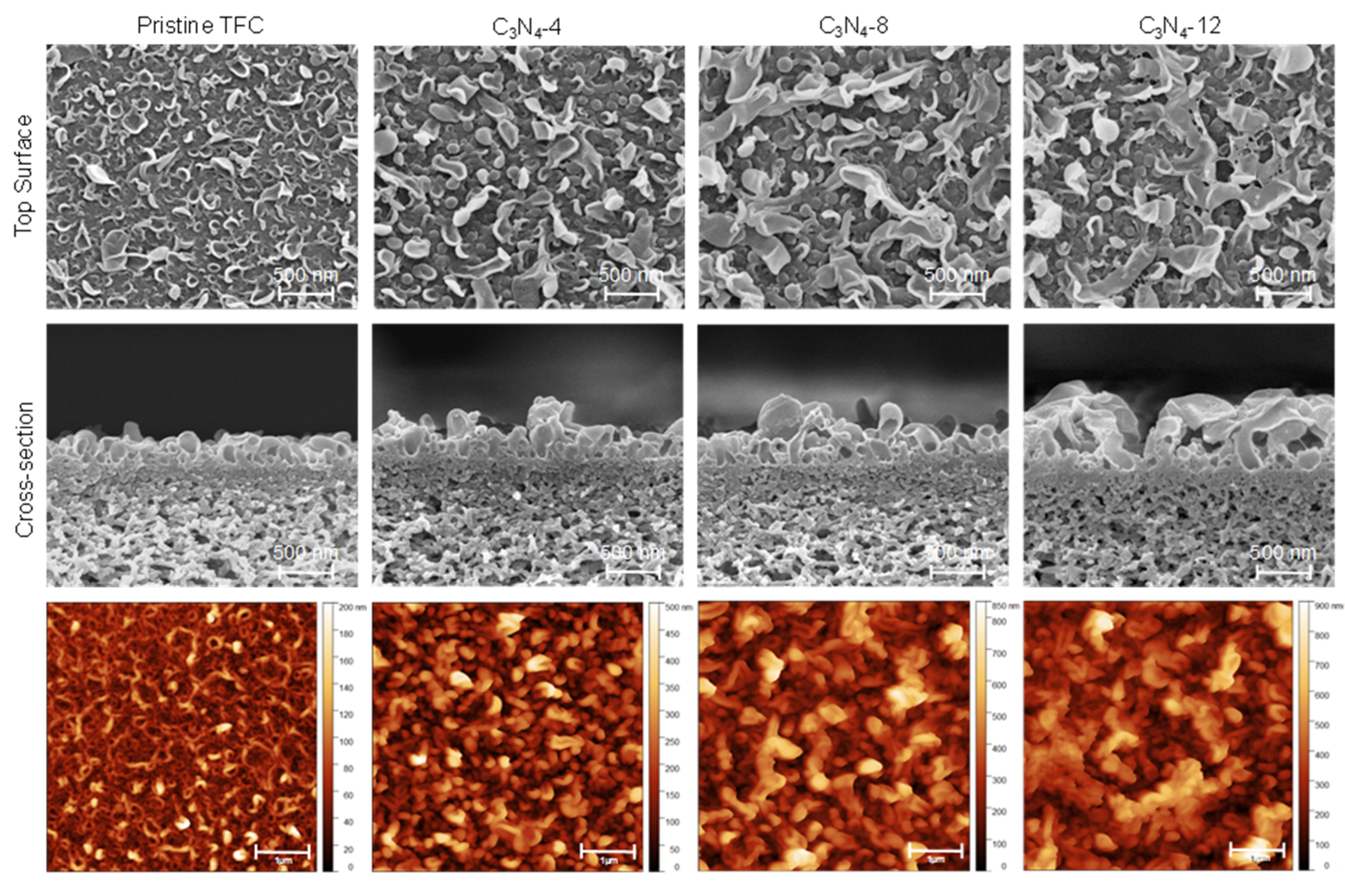
| Pristine | 0 | 1.4 ± 0.1 | 20.2 ± 5.6 | 260 ± 14 | 43.75 | 69 ± 11 |
| C3N4-4 | 0.04 | 1.7 ± 0.1 | 45.3 ± 6.2 | 380 ± 10 | 53.45 | 58 ± 7 |
| C3N4-8 | 0.08 | 2.1 ± 0.2 | 69.0 ± 6.1 | 505 ± 17 | 56.81 | 53 ± 8 |
| C3N4-12 | 0.12 | 2.3 ± 0.1 | 89.7 ± 8.4 | 650 ± 25 | 60.09 | 45 ± 9 |
© 2020 by the authors. Licensee MDPI, Basel, Switzerland. This article is an open access article distributed under the terms and conditions of the Creative Commons Attribution (CC BY) license (http://creativecommons.org/licenses/by/4.0/).
Share and Cite
Zhou, Z.; Li, X.; Shinde, D.B.; Sheng, G.; Lu, D.; Li, P.; Lai, Z. Tuning the Surface Structure of Polyamide Membranes Using Porous Carbon Nitride Nanoparticles for High-Performance Seawater Desalination. Membranes 2020, 10, 163. https://doi.org/10.3390/membranes10080163
Zhou Z, Li X, Shinde DB, Sheng G, Lu D, Li P, Lai Z. Tuning the Surface Structure of Polyamide Membranes Using Porous Carbon Nitride Nanoparticles for High-Performance Seawater Desalination. Membranes. 2020; 10(8):163. https://doi.org/10.3390/membranes10080163
Chicago/Turabian StyleZhou, Zongyao, Xiang Li, Digambar B. Shinde, Guan Sheng, Dongwei Lu, Peipei Li, and Zhiping Lai. 2020. "Tuning the Surface Structure of Polyamide Membranes Using Porous Carbon Nitride Nanoparticles for High-Performance Seawater Desalination" Membranes 10, no. 8: 163. https://doi.org/10.3390/membranes10080163
APA StyleZhou, Z., Li, X., Shinde, D. B., Sheng, G., Lu, D., Li, P., & Lai, Z. (2020). Tuning the Surface Structure of Polyamide Membranes Using Porous Carbon Nitride Nanoparticles for High-Performance Seawater Desalination. Membranes, 10(8), 163. https://doi.org/10.3390/membranes10080163