Article

Tuning the Surface Structure of Polyamide Membranes Using Porous Carbon Nitride Nanoparticles for High-Performance Seawater Desalination

Advanced Membranes and Porous Materials Center, Division of Physical Science and Engineering, King Abdullah University of Science and Technology (KAUST), Thuwal 23955-6900, Saudi Arabia
*
Author to whom correspondence should be addressed.
These authors contribute equally.
Membranes 2020, 10(8), 163; https://doi.org/10.3390/membranes10080163
Submission received: 17 June 2020 / Revised: 15 July 2020 / Accepted: 22 July 2020 / Published: 24 July 2020
(This article belongs to the Special Issue Membranes for Water and Wastewater Treatment)

Abstract

:
Enhancing the water flux while maintaining the high salt rejection of existing reverse osmosis membranes remains a considerable challenge. Herein, we report the use of a porous carbon nitride (C3N4) nanoparticle to potentially improve both the water flux and salt rejection of the state-of-the-art polyamide (PA) thin film composite (TFC) membranes. The organic–organic covalent bonds endowed C3N4 with great compatibility with the PA layer, which positively influenced the customization of interfacial polymerization (IP). Benefitting from the positive effects of C3N4, a more hydrophilic, more crumpled thin film nanocomposite (TFN) membrane with a larger surface area, and an increased cross-linking degree of PA layer was achieved. Moreover, the uniform porous structure of the C3N4 embedded in the ”ridge” sections of the PA layer potentially provided additional water channels. All these factors combined provided unprecedented performance for seawater desalination among all the PA-TFC membranes reported thus far. The water permeance of the optimized TFN membrane is 2.1-folds higher than that of the pristine PA-TFC membrane, while the NaCl rejection increased to 99.5% from 98.0%. Our method provided a promising way to improve the performance of the state-of-art PA-TFC membranes in seawater desalination.

Graphical Abstract

1. Introduction

Water scarcity is a global issue currently affecting about two-thirds of the world’s population [1]. Over the last half century, reverse osmosis (RO) has been demonstrated as an affordable approach to producing drinking water from seawater [2]. This is mainly owing to the successful development of the start-of-the-art RO membrane: a polyamide thin-film composite (PA-TFC) membrane consisting of a thin and highly cross-linked PA selective layer atop a strong and porous support layer [3,4,5,6,7,8]. However, similar to that of other types of membranes, further improvement in the PA-TFC membrane performance has been limited by the upper limit of the trade-off between permeability versus selectivity [8].
An effective approach to overcoming this limit is based on the concept of mixed matrix membranes. Hoek et al. demonstrated for the first time that by embedding zeolite 4A nanoparticles into the PA layer during interfacial polymerization (IP), the resultant thin film nanocomposite (TFN) membrane exhibited approximately a 50% improvement in water flux without considerable decline in salt rejection [9]. Since then, many other porous materials, such as zeolitic imidazolate frameworks [10,11,12], metal–organic frameworks [13], covalent organic frameworks [14], porous aromatic frameworks [15], and hyper-cross-linked polymers [16], have been extensively studied [17,18,19,20,21]. It is generally believed that these porous materials provide faster transport pathways for water and thus improve the membrane flux. However, there are several challenges in this approach. Firstly, the state-of-the-art PA-TFC membrane is approximately 100 nm thick [2,22]. To synthesize such small nanoparticles is costly and time-consuming. Secondly, it is difficult to increase the particle loading as this may cause particle agglomeration and render the membrane brittle. Lastly, many of these materials are unstable in water, which has raised concerns pertaining to their long-term stability.
Another approach to improving the membrane performance is to optimize the membrane surface structure. The PA layer of a PA-TFC membrane is typically prepared in situ via IP between a diamine and an acyl chloride dissolved in water and an organic solvent, respectively. The organic solvent is immiscible in water. Thus, upon contact, the two species diffuse from each solution to the phase boundary and react there to form a thin film. The reaction is fast, highly exothermic, and typically occurs in an uncontrolled manner; hence, the resultant membrane structure is extremely sensitive to local conditions. One notable feature is the formation of a rough ”ridge-and-valley” surface morphology, which is generally attributed to the inhomogeneous release of reaction heat [22,23,24]. The ridge-and-valley structure is very important for membrane performance because it can increase the membrane surface area [25,26]. Many innovative ideas have been developed to control the membrane surface structure by tuning the process of IP. Zhang et al. reported the formation of Turing patterns to increase the surface area and thus the membrane flux [27]. Jin et al. used a nanostructure-mediated IP process to increase the ridge-and-valley structure [26]. Livingston et al. introduced a sacrificial layer to tune the PA structure [23]. Several other publications have reported the use of a sublayer made of cellulose nanofibers [28], tannic acid/Fe3+ nanoscaffold [29], or carbon nanotubes [22,30] to optimize the process of IP. However, although these membranes demonstrate an improved water flux, their NaCl rejection values are generally low. Therefore, these membranes are good for nanofiltration but not suitable for seawater desalination as the latter requires a NaCl rejection value of more than 98.4% to reduce the seawater salinity to a potable level via a one-stage RO process.
Here, we report, for the first time, the use of the highly crystalline carbon nitride (C3N4) to tune the surface structure of PA membranes to enhance their performance in seawater desalination. As a graphene-analogue material, C3N4 has a 2D layered structure possessing uniform nanopores with a pore size of 3.11 Å, which is big enough to allow water molecules (kinetic diameter 2.65 Å) to pass through [31]. It has outstanding thermal and chemical stabilities, and is very stable in water and organic solvents [32,33,34]. Its synthesis is easy and inexpensive [35]. C3N4 has abundant amino ending groups, which render it hydrophilic and chemically very compatible with the PA layer. It was determined that embedding the C3N4 nanoparticles into the PA layer during the IP process could significantly enlarge the ridge-and-valley surface structure. This effect, as well as the additional transport pathway for water, substantially improved the water permeance of the membrane to 3.2 ± 0.2 Lm−2·h−1/bar (LMH/bar) and endowed it with an excellent NaCl rejection of 99.5%, which surpassed the performances of most TFN membranes reported to date.

2. Materials and Methods

2.1. Chemicals

Polysulfone (PSf, Ultrason® S 3010) was purchased from BASF (Frankfurt, Germany). N,N′-dimethylformamide, n-methyl-2-pyrrolidone (NMP), m-phenylenediamine (MPD), trimesoyl chloride (TMC), n-hexane, and melamine were all supplied by Sigma-Aldrich (St. Louis, MO, USA). Non-woven fabric was purchased from Sojitz (Osaka, Japan). NaCl was purchased from VWR Chemicals (Leuven, Belgium). All chemicals were used as received.

2.2. Synthesis of C3N4 Nanoparticles

C3N4 was prepared according to the literature [36]. Melamine powder was placed in an alumina crucible and first heated to 400 °C at a heating rate of 4.4 °C/min in an Ar atmosphere. The temperature was maintained at 400 °C for 90 min, and then raised to 600 °C at the same heating rate, held for another 120 min, and then cooled naturally to room temperature. The final product was collected in a yellow powder form (Figure S1).

2.3. Preparation of C3N4 Aqueous Suspension

A total of 30 mg of C3N4 powder was dispersed in 20 mL of deionized (DI) water using a probe ultrasonicator operated at 160 W and 25 °C for 5 h. The undispersed C3N4 powder was removed via centrifugation at 3000 rpm for 15 min. The supernatant solution was sonicated for another 2 h using an ultrasonic cleaner at 70 W and stored at room temperature for subsequent use as a stock solution (Figure S1). The particle concentration in the stock solution was approximately 0.6 mg/mL.

2.4. Preparation of PSf Porous Supports

A PSf ultrafiltration membrane was used as the support layer to prepare the TFC membrane. It was home-made using a previously reported method of non-solvent-induced phase separation [37]. A total of 12 g of PSf was first dried in a vacuum oven overnight at 90 °C and then dissolved in 88 g of NMP to form a homogenous casting solution. The casting solution was placed still for 12 h to remove air bubbles, and then cast on the surface of a non-woven fabric in a closed chamber using a casting knife with a gap of 200 µm. Prior to the casting, the non-woven fabric was wetted with NMP. The relative humidity (RH) and temperature of the casting chamber were maintained at 40% ± 5% RH and 25 ± 5 °C, respectively. The film obtained was immersed immediately into a room-temperature DI water bath and kept there for 12 h to remove most of the solvent. The film was stored at 4 °C for further use. The scanning electron microscopy (SEM) and atomic force microscopy (AFM) images, and the pure water flux of the PSf substrate prepared are shown in the Supporting Information (Figures S2–S4).

2.5. IP to Prepare PA-TFC Membrane

The process of IP was conducted according to our previous protocol [38]. The PSf support was first immersed in an MPD aqueous solution (3.4 wt.%) for 2 min and then withdrawn to naturally drain the MPD solution for 2 min. The excess MPD solution on the support surface was removed using a rubber roller. The TMC solution in hexane (0.15 wt.%) was then poured onto the support surface and reacted for 1 min. Afterwards, the excess TMC solution was removed and the membrane was cured in a hot water bath at 95 °C for 1 min. The final membrane was stored at 4 °C in DI water for further use (Figure S5).

2.6. IP to Prepare C3N4 TFN Membrane

The C3N4 stock solution was diluted to concentrations of 0.04 (C3N4-4), 0.08 (C3N4-8), and 0.12 (C3N4-12) mg/mL. Next, MPD was added to the solutions to attain a concentration of 3.4 wt.%. The concentration of the TMC solution was 0.15 wt.%. The remaining steps were identical to those in the preparation of the PA-TFC membrane via IP, as illustrated in Scheme 1.

2.7. Characterization

A high-resolution transmission electron microscopy (HRTEM, FEI Titan, Hillsboro, OR, USA) instrument was operated at 80 kV to obtain the TEM images. The TEM samples were prepared according to our previously reported procedure [22]. The SEM images were obtained using a Magellan XHR instrument (Hillsboro, OR, USA). The SEM samples of the back surface of the PA layer were prepared according to our previous report [22]. All the SEM samples were sputter-coated with 1 nm thick Ir. The dynamic light scattering (DLS) was measured using a Delsa Nano C system (Beckman Coulter, San Diego, CA, USA). The powder X-ray diffraction (PXRD) pattern was collected using a Bruker D8 Advance X-ray powder diffractometer (Karlsruhe, Germany). A Micromeritics ASAP 2420 analyzer (Norcross, GA, USA) was employed to record the N2 adsorption isotherms at 77 K. The solid-state nuclear magnetic resonance (NMR) data were obtained using a Bruker Advance 400 WB spectrometer (Karlsruhe, Germany). Atomic force microscopy (Bruker, Dimension Icon, Karlsruhe, Germany) was used to investigate the membrane surface roughness in the tapping mode. X-ray photoelectron spectroscopy (XPS, Amicus Kratos Analytical, ESCA 3400, Kratos, UK) was employed to measure the elemental composition of the PA layer. The water contact angles (WCAs) were measured using the sessile drop method on a drop shape analyzer (Kruss, DSA100, Hamburg, Germany) at room temperature.

2.8. Evaluation of RO Desalination Performance

The water permeance and NaCl rejection of the TFC and TFN membranes were measured using a custom-designed RO permeation cell [10]. After 1.5 h of pre-compaction, the membranes were tested at 15.5 bar and 2000 ppm of NaCl feed solution at 25 °C. The water permeance, Jw (LMH/bar), was calculated using Equation (1).
J w = V A × t × P
where V (L) is the permeate volume collected in a certain period of time, t (h), based on the filtration area, A (m2), and transmembrane pressure drop, ΔP (bar).
The NaCl rejection, R (%), was calculated using Equation (2).
R = 1 C p e r m e a t e C f e e d × 100 %
where C p e r m e a t e and C f e e d are the concentrations of the permeate and feed solutions, respectively.
The salt permeability, B (LMH), was calculated using Equation (3).
B = J w × P × 1 R R
All the membranes were tested on at least three samples, and the average values were obtained.

3. Results and Discussion

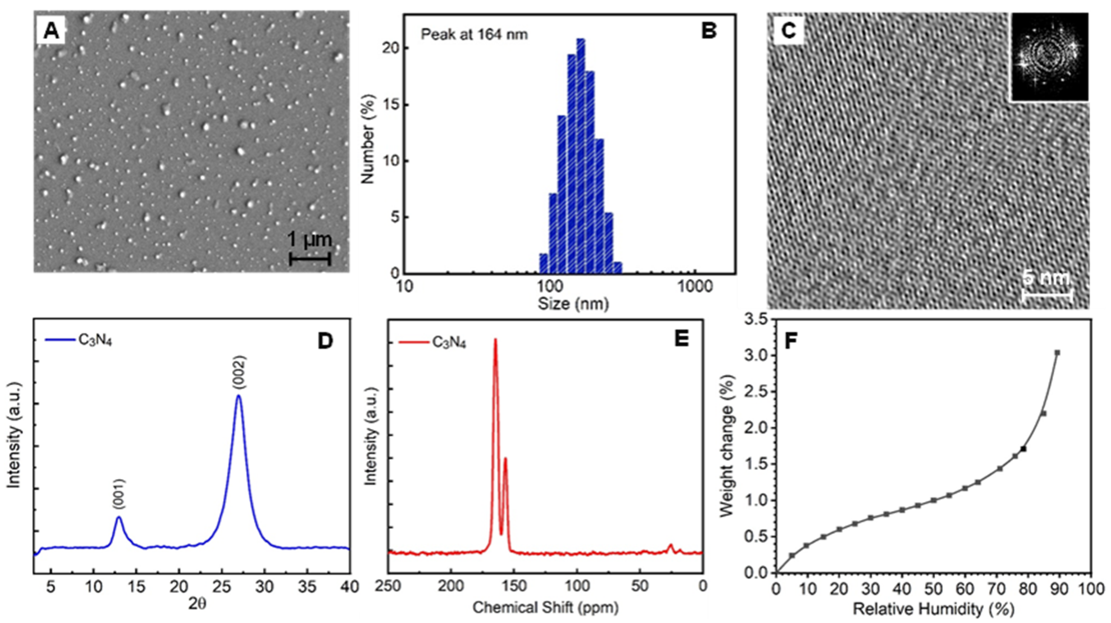
Figure 1A,B show the SEM image and DLS size analysis of the C3N4 nanoparticles, respectively. The average particle size was around 164 ± 30 nm. The HRTEM image in Figure 1C clearly shows the highly crystalline structure and regular pores, although the selective area electron diffraction displayed in the inset of Figure 1C indicates that the area studied was not a single layer. The high crystallinity was further confirmed by the PXRD pattern in Figure 1D, which contained two characteristic peaks at 13.1 and 27.5°. The PXRD pattern matched well with the reported graphitic C3N4 pattern [39,40]. Two apparent resonances (δ = 164 ppm and δ = 156 ppm) were detected in the 13C cross polarization-magic angle spinning (CP-MAS) spectrum, which were owing to the sp2 carbon atoms, as shown in Figure 1E [41]. All these results are in good agreement with the reported results [42], validating that a highly crystalline graphitic C3N4 was successfully synthesized. The N2 physisorption isotherm in Figure S6 indicates a very low Brunauer–Emmett–Teller (BET) surface area of 21.5 m2/g. This is because the molecular size of N2 (3.64 Å) was greater than the pore size of C3N4. Figure 1F presents the water vapor adsorption isotherm at room temperature and indicates that C3N4 was relatively hydrophilic. The water uptake at 90% RH was approximately 3 wt.%, which is approximately 15 times higher than that of the reported ZIF-8 nanoparticles [10].
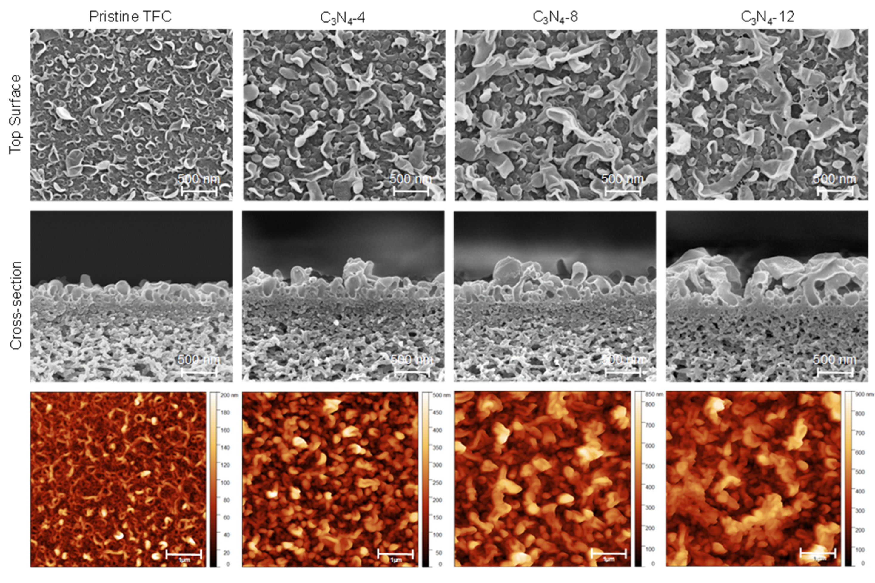
Figure 2 shows the morphologies of the PA-TFC and the C3N4 TFN membranes at different C3N4 concentrations, as listed in Table 1. The surface morphologies of all membranes showed the ridge-and-valley feature, but the feature size increased notably with the concentration of C3N4. The cross-section additionally showed that the height of the PA layer increased with the loading rate of C3N4. The surface roughness (Ra) was measured via AFM. The Ra of the pristine PA-TFC membrane was 20.2 ± 5.6 nm whereas that of C3N4-12 was 89.7 ± 5.6 nm, representing a considerable increase of four-fold (Table 1). The surface area ratio (SAR), which is defined as the ratio of the total surface area to the projected surface area, increased from 1.4 ± 0.1 for the pristine membrane to 2.3 ± 0.1 for the C3N4-12 membrane (Table 1). The higher SAR implies a larger specific surface area for transport, which is beneficial to achieving higher water permeation [26].
As shown in Figure S7 and Table S1, the O/N ratio of the membrane surface decreased from 1.46 to 1.31 as the concentration of the C3N4 nanoparticles increased (Table 1). This can be attributed to two factors: (1) the increase in N resulting from the loading of the nanoparticles into the PA layer; (2) the higher apparent cross-linking degree (CLD) of the PA layer under the effects of the C3N4 nanoparticles on the process of IP. It is well-known that increasing the CLD will increase the salt rejection [22,43,44]. On the other hand, the uniform nanopores of C3N4 are also expected to give high salt rejection. Thus, in both cases it is beneficial to the membrane salt rejection, which explains the experimental observation where the NaCl rejection improved as the concentration of C3N4 nanoparticles increased in the order of pristine TFC < C3N4-4 < C3N4-8. Interestingly, the result is different from that reported for TFN membranes with incorporated ZIFs [10,11] or zeolites [45,46]. Those traditional TFN membranes exhibited lower CLDs of the PA layers and lower salt rejection following the addition of the organic/hybrid nanomaterials. Therefore, we tentatively confirmed that, compared with zeolite or other inorganic nanoparticles, the C3N4 nanoparticles in the present study have better compatibility with the polymer network structure and a much more positive influence on the customization of the IP. Furthermore, the C3N4 nanoparticles did not compete with MPD or TMC, whereas some nanoparticles modified with active groups [47], interfered with the IP and decreased the CLD of the PA layer, resulting in the loss of salt rejection. The WCA of the PA-TFC membrane was approximately 69 ± 11°. It decreased with the increase in the concentration of C3N4 (Table 1) and reached 45 ± 9° for the C3N4-12 membrane. The hydrophilic nature of C3N4 and the rougher surface should be the two possible reasons for these characteristic results.
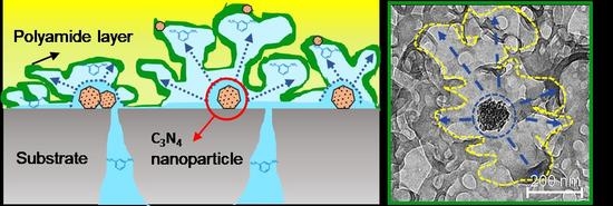
To understand the function of C3N4, the pristine PA-TFC and C3N4-8 membranes were studied in detail via TEM, as shown in Figure 3. In the PA-TFC membrane, the PA layer exhibited a hollow ridge-and-valley structure with a layer thickness of approximately 20–30 nm (Figure 3A), which was similar to that observed in our previous studies [22] and in the literature [23,48]. In the TFN membrane, the layer thickness was similar, but the ridge-and-valley structure was much larger than that of the PA-TFC membrane. A possible mechanism is proposed as follows. Interestingly, it was found that small C3N4 particles were clearly embedded into the PA layer, as indicated by the yellow arrows, but the bigger C3N4 nanoparticles (approximately over 150 nm) always sat in the middle of the ridge-and-valley structure, as shown in Figure 3B1–B4. A possible mechanism is proposed as follows. The large and hydrophilic C3N4 nanoparticles can trap more MPD solution, as demonstrated by the vapor adsorption isotherm in Figure 1F. It forms a heterogenous reaction zone. The heat generated from the IP reaction further promotes the reaction and breaks the interfacial stability [22,23], thus leading to a larger ridge-and-valley feature. In the case of smaller particles, the influence on the reaction is weak, and thus they are embedded into the PA layer.
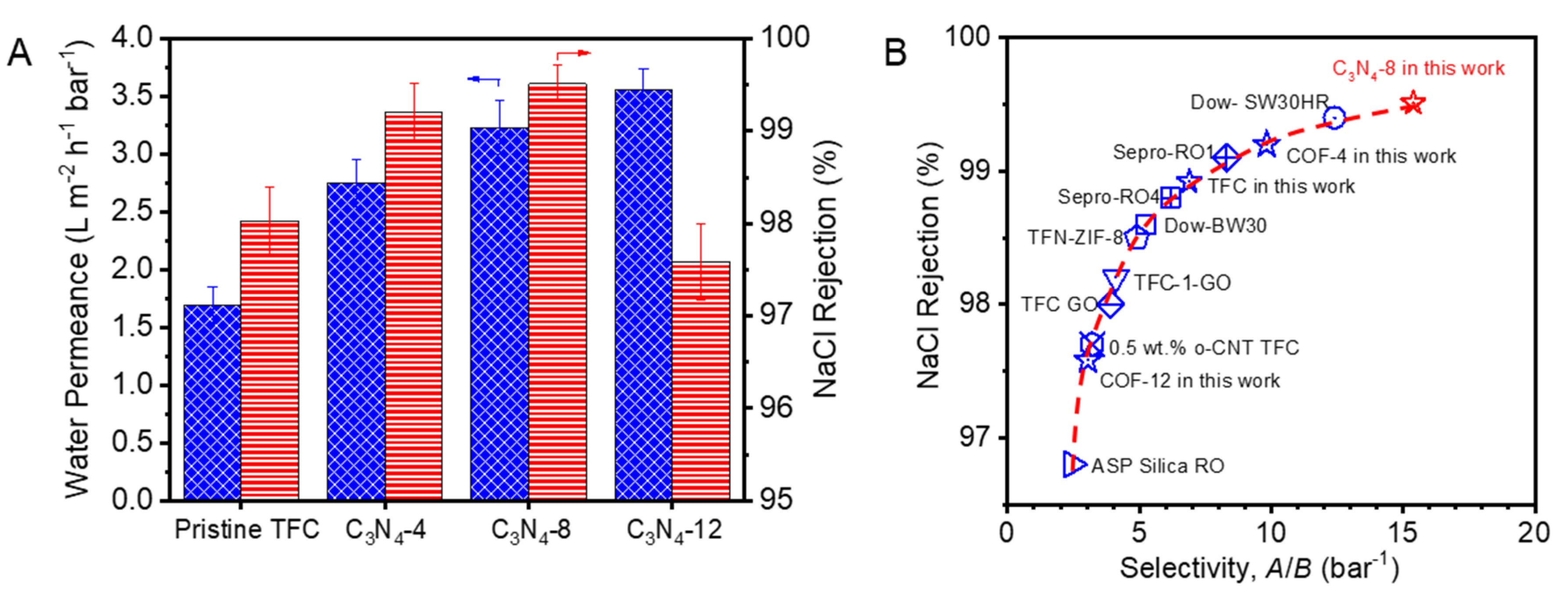
The RO desalination performance is shown in Figure 4 and Table S2. The PA-TFC membrane exhibited a water permeance of 1.7 ± 0.2 LMH/bar with a NaCl rejection of 98.0% ± 0.4%, which were similar to those reported in the literature under the same testing conditions [17,49,50,51,52]. The permeance of the TFN membranes increased with the loading rate of C3N4. The rejection increased for the C3N4-4 and C3N4-8 membranes too but declined for the C3N4-12 membrane. For the optimal C3N4-8 membrane, the water permeance reached 3.6 ± 0.2 LMH/bar and the rejection increased to 99.5% ± 0.2%, which is 2.1-folds higher than the permeance of the PA-TFC membrane. Obviously, the enlarged ridge-and-valley structure contributed to the higher water permeance, but its contribution was approximately 1.6-folds according to the SAR. The remaining part was possibly owing to the additional channels provided by the C3N4 nanoparticles embedded in the PA layer. The higher salt rejections of the C3N4-4 and C3N4-8 membranes were because of their higher CLD, as shown in Table 1. However, further increasing the particle loading caused particle agglomeration and defects as shown in Figure S8. Thus, the salt rejection declined.
The long-term flux of the prepared TFC and TFN membranes was measured to assess their stability during compaction incurred by high-pressure compression. As shown in Figure S9, the normalized steady-state permeance of the membranes approached 0.75–0.80, which is consistent with the literature reported values [49]. There is no significant difference in terms of the steady-state permeance between the pristine TFC membrane and the TFN membranes with various loadings of C3N4 particles. Thus, the initial reduction in water permeance should be attributed mainly to the compaction of the PSf supports. The C3N4-8 membrane showed high salt rejection over 99.5% after 48 h testing, which indicated that C3N4 particles have good compatibility with the PA layer and the resulting TFN membranes have sufficient stability in seawater desalination applications. The performance of the C3N4-8 membrane was compared with those of other reported TFN systems on the basis of the coefficient (Jw/B), as shown in Figure 4B [10,49,50,53,54]. The C3N4-8 membrane showed an unprecedented Jw/B value of up to 15.4, which is superior to that of not only state-of-the art commercial RO membranes, such as Dow® BW30 and Dow® SW30HR, but also other reported TFN membranes.

4. Conclusions

In conclusion, we demonstrated that the highly crystalline C3N4 could not only provide a faster transport pathway but also effectively tune the structure of PA by tailoring the process of IP to enhance both the water flux and salt rejection. It was found that the crystalline C3N4 was hydrophilic, containing regular pores that could adsorb a significant amount of water. The organic–organic covalent bonds endowed C3N4 with great compatibility with the PA layer, which positively influenced the customization of IP. With the increasing loading rate of C3N4, the size of the “ridge-and-valley” surface structure, the surface area ratio, and the surface hydrophilicity all increased compared to the pristine PA-TFC membrane. Moreover, the cross-linking degree (CLD) also increased with C3N4 loading rate, which was different from other nanoparticle filler systems. As a result, both the membrane flux and salt rejection were improved. Under the optimal conditions (C3N4-8), the water permeance was 2.1-folds higher than that of the pristine TFC membrane, while the NaCl rejection increased to 99.5% from 98.0%. Our method thus provided a promising way to improve the performance of the state-of-art PA-TFC membranes in seawater desalination.

Supplementary Materials

The following are available online at https://www.mdpi.com/2077-0375/10/8/163/s1, Figure S1: Optical photographs of C3N4 powders and the aqueous solution, Figure S2: SEM images of the prepared PSf substrate, Figure S3: AFM image of the prepared PSf substrate, Figure S4: Pure water flux of the prepared PSf substrate, Figure S5: Optical photographs of the prepared pristine TFC and TFN membranes, Figure S6: N2 adsorption isotherm (G), and pore size distribution (G inset) of the prepared C3N4, Figure S7: O/N ration of PA layer fabricated with various amounts C3N4 nanosheets. The degree of cross-linking was calculated by X X + Y × 100 % , where X and Y were calculated from the following equations, 3X + 4Y = O1s and 3X + 2Y = N1s, Figure S8: SEM images of C3N4 deposition on PSf support and surface coverage of the deposited particles on supports, as measured by Image J software, Figure S9: Normalized water permeance under long-term operation, Table S1: Elementary composition of PA layer with various C3N4 amount, Table S2: Jw, B and R of TFC and TFN membranes, Table S3: Comparison of the A, B and R of TFC and TFN membranes reported in references and in this work.

Author Contributions

Conceptualization, Z.Z. and Z.L.; methodology, Z.Z. and X.L.; validation, Z.Z. and Z.L.; formal analysis, Z.Z. and X.L.; investigation, Z.Z., D.B.S., G.S., D.L. and P.L.; resources, Z.L.; data curation, Z.Z., X.L., D.B.S., G.S., D.L. and P.L.; writing—original draft preparation, Z.Z.; writing—review and editing, Z.L.; visualization, Z.Z.; supervision, Z.L.; project administration, Z.L.; funding acquisition, Z.L. All authors have read and agreed to the published version of the manuscript.

Funding

This research was funded by King Abdullah University of Science and Technology, Saudi Arabia, under the competitive research grant URF/1/3435-01.

Conflicts of Interest

The authors declare no conflict of interest.

References

  1. Mekonnen, M.M.; Hoekstra, A.Y. Four billion people facing severe water scarcity. Sci. Adv. 2016, 2, e1500323. [Google Scholar] [CrossRef] [PubMed] [Green Version]
  2. Hoover, L.A.; Phillip, W.A.; Tiraferri, A.; Yip, N.Y.; Elimelech, M. Forward with osmosis: Emerging applications for greater sustainability. Environ. Sci. Technol. 2011, 45, 9824–9830. [Google Scholar] [CrossRef]
  3. Kim, B.; Gwak, G.; Hong, S. Review on methodology for determining forward osmosis (FO) membrane characteristics: Water permeability (A), solute permeability (B), and structural parameter (S). Desalination 2017, 422, 5–16. [Google Scholar] [CrossRef]
  4. Klaysom, C.; Cath, T.Y.; Depuydt, T.; Vankelecom, I.F. Forward and pressure retarded osmosis: Potential solutions for global challenges in energy and water supply. Chem. Soc. Rev. 2013, 42, 6959–6989. [Google Scholar] [CrossRef] [PubMed]
  5. Shaffer, D.L.; Werber, J.R.; Jaramillo, H.; Lin, S.; Elimelech, M. Forward osmosis: Where are we now? Desalination 2015, 356, 271–284. [Google Scholar] [CrossRef]
  6. Choi, W.; Gu, J.-E.; Park, S.-H.; Kim, S.; Bang, J.; Baek, K.-Y.; Park, B.; Lee, J.S.; Chan, E.P.; Lee, J.-H. Tailor-Made Polyamide Membranes for Water Desalination. ACS Nano 2015, 9, 345–355. [Google Scholar] [CrossRef]
  7. Chowdhury, M.R.; Steffes, J.; Huey, B.D.; McCutcheon, J.R. 3D printed polyamide membranes for desalination. Science 2018, 361, 682–686. [Google Scholar] [CrossRef] [Green Version]
  8. Geise, G.M.; Park, H.B.; Sagle, A.C.; Freeman, B.D.; Mcgrath, J.E. Water permeability and water/salt selectivity tradeoff in polymers for desalination. J. Membr. Sci. 2011, 369, 130–138. [Google Scholar] [CrossRef]
  9. Jeong, B.-H.; Hoek, E.M.; Yan, Y.; Subramani, A.; Huang, X.; Hurwitz, G.; Ghosh, A.K.; Jawor, A. Interfacial polymerization of thin film nanocomposites: A new concept for reverse osmosis membranes. J. Membr. Sci. 2007, 294, 1–7. [Google Scholar] [CrossRef]
  10. Duan, J.; Pan, Y.; Pacheco, F.; Litwiller, E.; Lai, Z.; Pinnau, I. High-performance polyamide thin-film-nanocomposite reverse osmosis membranes containing hydrophobic zeolitic imidazolate framework-8. J. Membr. Sci. 2015, 476, 303–310. [Google Scholar] [CrossRef]
  11. Wang, L.; Fang, M.; Liu, J.; He, J.; Deng, L.; Li, J.; Lei, J. The influence of dispersed phases on polyamide/ZIF-8 nanofiltration membranes for dye removal from water. RSC Adv. 2015, 5, 50942–50954. [Google Scholar] [CrossRef]
  12. Wang, F.; Zheng, T.; Xiong, R.; Wang, P.; Ma, J. Strong improvement of reverse osmosis polyamide membrane performance by addition of ZIF-8 nanoparticles: Effect of particle size and dispersion in selective layer. Chemosphere 2019, 233, 524–531. [Google Scholar] [CrossRef] [PubMed]
  13. Van Goethem, C.; Verbeke, R.; Pfanmöller, M.; Koschine, T.; Dickmann, M.; Timpel-Lindner, T.; Egger, W.; Bals, S.; Vankelecom, I.F. The role of MOFs in thin-film nanocomposite (TFN) membranes. J. Membr. Sci. 2018, 563, 938–948. [Google Scholar] [CrossRef]
  14. Li, C.; Li, S.; Tian, L.; Zhang, J.; Su, B.; Hu, M.Z. Covalent organic frameworks (COFs)-incorporated thin film nanocomposite (TFN) membranes for high-flux organic solvent nanofiltration (OSN). J. Membr. Sci. 2019, 572, 520–531. [Google Scholar] [CrossRef]
  15. Wu, S.; Li, M.; Phan, H.; Wang, D.; Herng, T.S.; Ding, J.; Lu, Z.; Wu, J. Toward two-dimensional pi-conjugated covalent organic radical frameworks. Angew. Chem. Int. Ed. 2018, 57, 8007–8011. [Google Scholar] [CrossRef]
  16. Lau, W.J.; Gray, S.; Matsuura, T.; Emadzadeh, D.; Chen, J.P.; Ismail, A.F. A review on polyamide thin film nanocomposite (TFN) membranes: History, applications, challenges and approaches. Water Res. 2015, 80, 306–324. [Google Scholar] [CrossRef]
  17. Duan, J.; Litwiller, E.; Pinnau, I. Preparation and water desalination properties of POSS-polyamide nanocomposite reverse osmosis membranes. J. Membr. Sci. 2015, 473, 157–164. [Google Scholar] [CrossRef]
  18. Dong, H.; Zhao, L.; Zhang, L.; Chen, H.; Gao, C.; Ho, W.W. High-flux reverse osmosis membranes incorporated with NaY zeolite nanoparticles for brackish water desalination. J. Membr. Sci. 2015, 476, 373–383. [Google Scholar] [CrossRef]
  19. Guo, F.; Servi, A.; Liu, A.; Gleason, K.K.; Rutledge, G.C. Desalination by membrane distillation using electrospun polyamide fiber membranes with surface fluorination by chemical vapor deposition. ACS Appl. Mater. Interfaces 2015, 7, 8225–8232. [Google Scholar] [CrossRef] [PubMed] [Green Version]
  20. Ma, D.; Peh, S.B.; Han, G.; Chen, S.B. Thin-film nanocomposite (TFN) membranes incorporated with super-hydrophilic metal–organic framework (MOF) UiO-66: Toward enhancement of water flux and salt rejection. ACS Appl. Mater. Interfaces 2017, 9, 7523–7534. [Google Scholar] [CrossRef]
  21. Gupta, K.M.; Zhang, K.; Jiang, J. Water desalination through zeolitic imidazolate framework membranes: Significant role of functional groups. Langmuir 2015, 31, 13230–13237. [Google Scholar] [CrossRef]
  22. Zhou, Z.; Hu, Y.; Boo, C.; Liu, Z.; Li, J.; Deng, L.; An, X. High-Performance Thin-Film Composite Membrane with an Ultrathin Spray-Coated Carbon Nanotube Interlayer. Environ. Sci. Technol. Lett. 2018, 5, 243–248. [Google Scholar] [CrossRef]
  23. Santanu, K.; Jiang, Z.; Livingston, A.G. Sub–10 nm polyamide nanofilms with ultrafast solvent transport for molecular separation. Science 2015, 348, 1347–1351. [Google Scholar]
  24. Ma, X.-H.; Yao, Z.-K.; Yang, Z.; Guo, H.; Xu, Z.-L.; Tang, C.Y.; Elimelech, M. Nanofoaming of Polyamide Desalination Membranes To Tune Permeability and Selectivity. Environ. Sci. Technol. Lett. 2018, 5, 123–130. [Google Scholar] [CrossRef]
  25. Pacheco, F.; Pinnau, I.; Reinhard, M.; Leckie, J. Characterization of isolated polyamide thin films of RO and NF membranes using novel TEM techniques. J. Membr. Sci. 2010, 358, 51–59. [Google Scholar] [CrossRef]
  26. Wang, Z.; Wang, Z.; Lin, S.; Jin, H.; Gao, S.; Zhu, Y.; Jin, J. Nanoparticle-templated nanofiltration membranes for ultrahigh performance desalination. Nat. Commun. 2018, 9, 1–9. [Google Scholar] [CrossRef]
  27. Tan, Z.; Chen, S.; Peng, X.; Zhang, L.; Gao, C. Polyamide membranes with nanoscale Turing structures for water purification. Science 2018, 360, 518–521. [Google Scholar] [CrossRef] [Green Version]
  28. Wang, J.-J.; Yang, H.-C.; Wu, M.-B.; Zhang, X.; Xu, Z.-K. Nanofiltration membranes with cellulose nanocrystals as an interlayer for unprecedented performance. J. Mater. Chem. A 2017, 5, 16289–16295. [Google Scholar] [CrossRef]
  29. Yang, Z.; Zhou, Z.W.; Guo, H.; Yao, Z.; Ma, X.H.; Song, X.; Feng, S.P.; Tang, C.Y. Tannic acid/Fe3+ nanoscaffold for Interfacial polymerization: Toward enhanced nanofiltration performance. Environ. Sci. Technol. 2018, 52, 9341–9349. [Google Scholar] [CrossRef]
  30. Zhu, Y.; Xie, W.; Gao, S.; Zhang, F.; Zhang, W.; Liu, Z.; Jin, J. Single-Walled Carbon Nanotube Film Supported Nanofiltration Membrane with a Nearly 10 nm Thick Polyamide Selective Layer for High-Flux and High-Rejection Desalination. Small 2016, 12, 5034–5041. [Google Scholar] [CrossRef]
  31. Cao, K.; Jiang, Z.; Zhang, X.; Zhang, Y.; Zhao, J.; Xing, R.; Yang, S.; Gao, C.; Pan, F. Highly water-selective hybrid membrane by incorporating g-C3N4 nanosheets into polymer matrix. J. Membr. Sci. 2015, 490, 72–83. [Google Scholar] [CrossRef]
  32. Ye, W.; Liu, H.; Lin, F.; Lin, J.; Zhao, S.; Yang, S.; Hou, J.; Zhou, S.; Van der Bruggen, B. High-flux nanofiltration membranes tailored by bio-inspired co-deposition of hydrophilic g-C3N4 nanosheets for enhanced selectivity towards organics and salts. Environ. Sci. Nano 2019, 6, 2958–2967. [Google Scholar] [CrossRef]
  33. Zhang, X.; Xie, X.; Wang, H.; Zhang, J.; Pan, B.; Xie, Y. Enhanced photoresponsive ultrathin graphitic-phase C3N4 nanosheets for bioimaging. J. Am. Chem. Soc. 2013, 135, 18–21. [Google Scholar] [CrossRef]
  34. She, X.; Xu, H.; Xu, Y.; Yan, J.; Xia, J.; Xu, L.; Song, Y.; Jiang, Y.; Zhang, Q.; Li, H. Exfoliated graphene-like carbon nitride in organic solvents: Enhanced photocatalytic activity and highly selective and sensitive sensor for the detection of trace amounts of Cu2+. J. Mater. Chem. A 2014, 2, 2563–2570. [Google Scholar] [CrossRef]
  35. Wang, Y.; Wang, X.; Antonietti, M. Polymeric graphitic carbon nitride as a heterogeneous organocatalyst: From photochemistry to multipurpose catalysis to sustainable chemistry. Angew. Chem. Int. Ed. 2012, 51, 68–89. [Google Scholar] [CrossRef] [PubMed]
  36. Kale, V.S.; Sim, U.; Yang, J.; Jin, K.; Chae, S.I.; Chang, W.J.; Sinha, A.K.; Ha, H.; Hwang, C.C.; An, J.; et al. Sulfur-Modified Graphitic Carbon Nitride Nanostructures as an Efficient Electrocatalyst for Water Oxidation. Small 2017, 13, 1603893. [Google Scholar] [CrossRef] [PubMed]
  37. Liu, Z.; An, X.; Dong, C.; Zheng, S.; Mi, B.; Hu, Y. Modification of thin film composite polyamide membranes with 3D hyperbranched polyglycerol for simultaneous improvement in their filtration performance and antifouling properties. J. Mater. Chem. A 2017, 5, 23190–23197. [Google Scholar] [CrossRef]
  38. Zhou, Z.; Lu, D.; Li, X.; Rehman, L.M.; Roy, A.; Lai, Z. Fabrication of highly permeable polyamide membranes with large “leaf-like” surface nanostructures on inorganic supports for organic solvent nanofiltration. J. Membr. Sci. 2020, 601, 117932. [Google Scholar] [CrossRef]
  39. Bellardita, M.; García-López, E.I.; Marcì, G.; Krivtsov, I.; García, J.R.; Palmisano, L. Selective photocatalytic oxidation of aromatic alcohols in water by using P-doped g-C3N4. Appl. Catal. B 2018, 220, 222–233. [Google Scholar] [CrossRef] [Green Version]
  40. Xue, J.; Ma, S.; Zhou, Y.; Zhang, Z.; He, M. Facile photochemical synthesis of Au/Pt/g-C3N4 with plasmon-enhanced photocatalytic activity for antibiotic degradation. ACS Appl. Mater. Interfaces 2015, 7, 9630–9637. [Google Scholar] [CrossRef]
  41. Gao, H.; Yan, S.; Wang, J.; Zou, Z. Ion coordination significantly enhances the photocatalytic activity of graphitic-phase carbon nitride. Dalton Trans. 2014, 43, 8178–8183. [Google Scholar] [CrossRef]
  42. Zou, X.; Silva, R.; Goswami, A.; Asefa, T. Cu-doped carbon nitride: Bio-inspired synthesis of H2-evolving electrocatalysts using graphitic carbon nitride (g-C3N4) as a host material. Appl. Surf. Sci. 2015, 357, 221–228. [Google Scholar] [CrossRef] [Green Version]
  43. Ghosh, A.K.; Hoek, E.M. Impacts of support membrane structure and chemistry on polyamide–polysulfone interfacial composite membranes. J. Membr. Sci. 2009, 336, 140–148. [Google Scholar] [CrossRef]
  44. Huang, L.; McCutcheon, J.R. Impact of support layer pore size on performance of thin film composite membranes for forward osmosis. J. Membr. Sci. 2015, 483, 25–33. [Google Scholar] [CrossRef]
  45. Huang, H.; Qu, X.; Dong, H.; Zhang, L.; Chen, H. Role of NaA zeolites in the interfacial polymerization process towards a polyamide nanocomposite reverse osmosis membrane. RSC Adv. 2013, 3, 8203–8207. [Google Scholar] [CrossRef]
  46. Lind, M.L.; Eumine Suk, D.; Nguyen, T.-V.; Hoek, E.M. Tailoring the structure of thin film nanocomposite membranes to achieve seawater RO membrane performance. Environ. Sci. Technol. 2010, 44, 8230–8235. [Google Scholar] [CrossRef]
  47. Xue, S.-M.; Xu, Z.-L.; Tang, Y.-J.; Ji, C.-H. Polypiperazine-amide nanofiltration membrane modified by different functionalized multiwalled carbon nanotubes (MWCNTs). ACS Appl. Mater. Interfaces 2016, 8, 19135–19144. [Google Scholar] [CrossRef] [PubMed]
  48. Yan, H.; Miao, X.; Xu, J.; Pan, G.; Zhang, Y.; Shi, Y.; Guo, M.; Liu, Y. The porous structure of the fully-aromatic polyamide film in reverse osmosis membranes. J. Membr. Sci. 2015, 475, 504–510. [Google Scholar] [CrossRef]
  49. Lee, J.; Wang, R.; Bae, T.-H. High-performance reverse osmosis membranes fabricated on highly porous microstructured supports. Desalination 2018, 436, 48–55. [Google Scholar] [CrossRef]
  50. Ali, M.E.; Wang, L.; Wang, X.; Feng, X. Thin film composite membranes embedded with graphene oxide for water desalination. Desalination 2016, 386, 67–76. [Google Scholar] [CrossRef]
  51. Chong, C.; Lau, W.; Yusof, N.; Lai, G.; Othman, N.; Matsuura, T.; Ismail, A. Studies on the properties of RO membranes for salt and boron removal: Influence of thermal treatment methods and rinsing treatments. Desalination 2018, 428, 218–226. [Google Scholar] [CrossRef]
  52. Kotp, Y.H.; Shebl, Y.A.; El-Deab, M.S.; El-Anadouli, B.E.; Shawky, H.A. Performance enhancement of PA-TFC RO membrane by using magnesium silicate nanoparticles. J. Inorg. Organomet. Polym. Mater. 2017, 27, 201–214. [Google Scholar] [CrossRef]
  53. Lee, J.; Jang, J.H.; Chae, H.-R.; Lee, S.H.; Lee, C.-H.; Park, P.-K.; Won, Y.-J.; Kim, I.-C. A facile route to enhance the water flux of a thin-film composite reverse osmosis membrane: Incorporating thickness-controlled graphene oxide into a highly porous support layer. J. Mater. Chem. A 2015, 3, 22053–22060. [Google Scholar] [CrossRef]
  54. Li, Q.; Yu, H.; Wu, F.; Song, J.; Pan, X.; Zhang, M. Fabrication of semi-aromatic polyamide/spherical mesoporous silica nanocomposite reverse osmosis membrane with superior permeability. Appl. Surf. Sci. 2016, 363, 338–345. [Google Scholar] [CrossRef]
Scheme 1. Schematic illustration of the fabrication of thin film composite (TFC) and thin film nanocomposite (TFN) membranes.
Membranes 10 00163 sch001
Figure 1. Characterization of C3N4 nanoparticles: (A) SEM image, (B) particle size distribution of C3N4 nanoparticles dispersed in aqueous solution, (C) typical high-resolution transmission electron microscopy (HRTEM) image with the inset showing a fast Fourier transform of the electron diffraction pattern, (D) powder X-ray diffraction (PXRD) spectra, (E) 13C CP-MAS spectrum, and (F) water vapor adsorption isotherm at room temperature.
Membranes 10 00163 g001
Figure 2. SEM and atomic force microscopy (AFM) images of pristine TFC and TFN membranes with different amounts of C3N4 nanoparticles.
Membranes 10 00163 g002
Figure 3. TEM images of (A) pristine PA without C3N4, and (B, B1, B2, B3, and B4) PA with C3N4. The yellow circles indicate large C3N4 nanoparticles and the arrows indicate small nanoparticles.
Membranes 10 00163 g003
Figure 4. (A) Water permeance and NaCl rejection of pristine TFC and TFN membranes, and (B) reverse osmosis (RO) performance towards NaCl rejection and selectivity from the present study and the literature. (References are listed in Table S3.).
Membranes 10 00163 g004
Table 1. Properties of the polyamide (PA) layer with various amounts of C3N4 nanoparticles.
MembraneC3N4 Concentration
[mg/mL]
SARRa
[nm]
Height
[nm]
CLD
[%]
WCA
[°]
Pristine01.4 ± 0.120.2 ± 5.6260 ± 1443.7569 ± 11
C3N4-40.041.7 ± 0.145.3 ± 6.2380 ± 1053.4558 ± 7
C3N4-80.082.1 ± 0.269.0 ± 6.1505 ± 1756.8153 ± 8
C3N4-120.122.3 ± 0.189.7 ± 8.4650 ± 2560.0945 ± 9