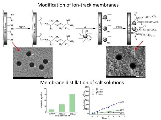
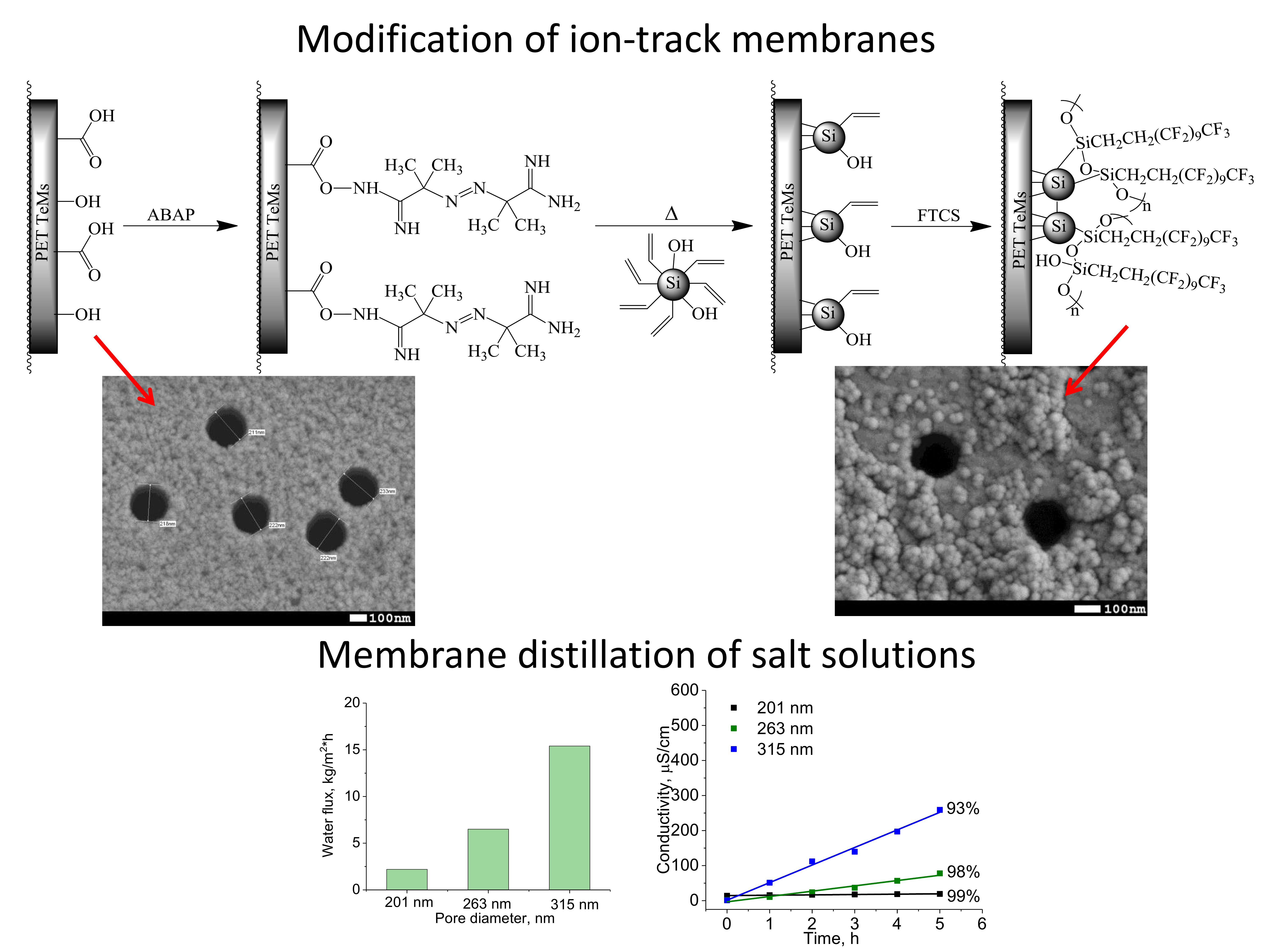
Modification of PET Ion-Track Membranes by Silica Nanoparticles for Direct Contact Membrane Distillation of Salt Solutions

 ,
, 
Abstract
1. Introduction
2. Materials and Methods
2.1. Chemicals
2.2. Synthesis of the Silica Nanoparticles
2.3. Fabrication of Ion-Track Membranes and Their Modification by Silica NPs
2.4. Methods of Characterization
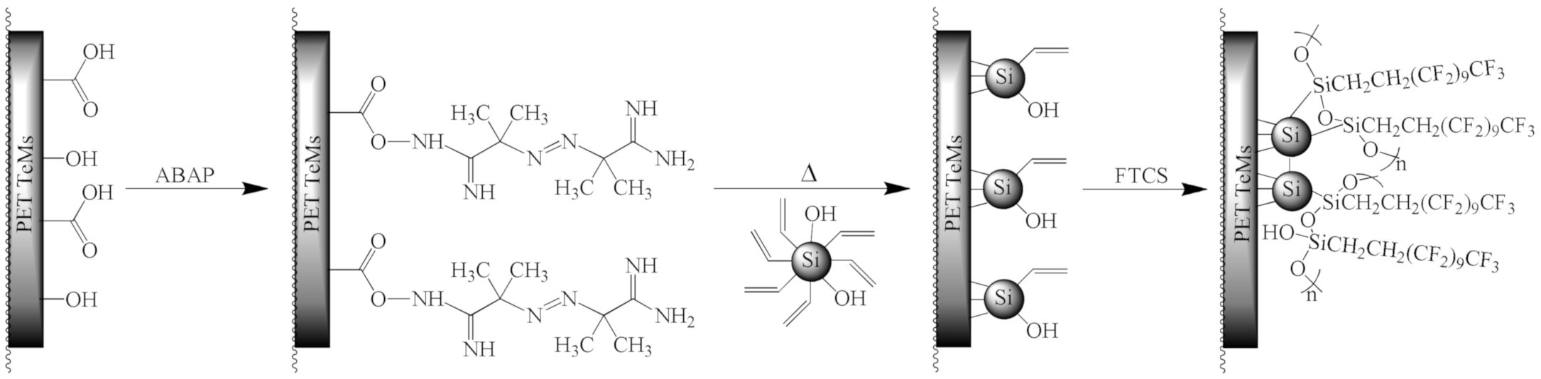
2.5. Direct Contact Membrane Distillation
3. Results
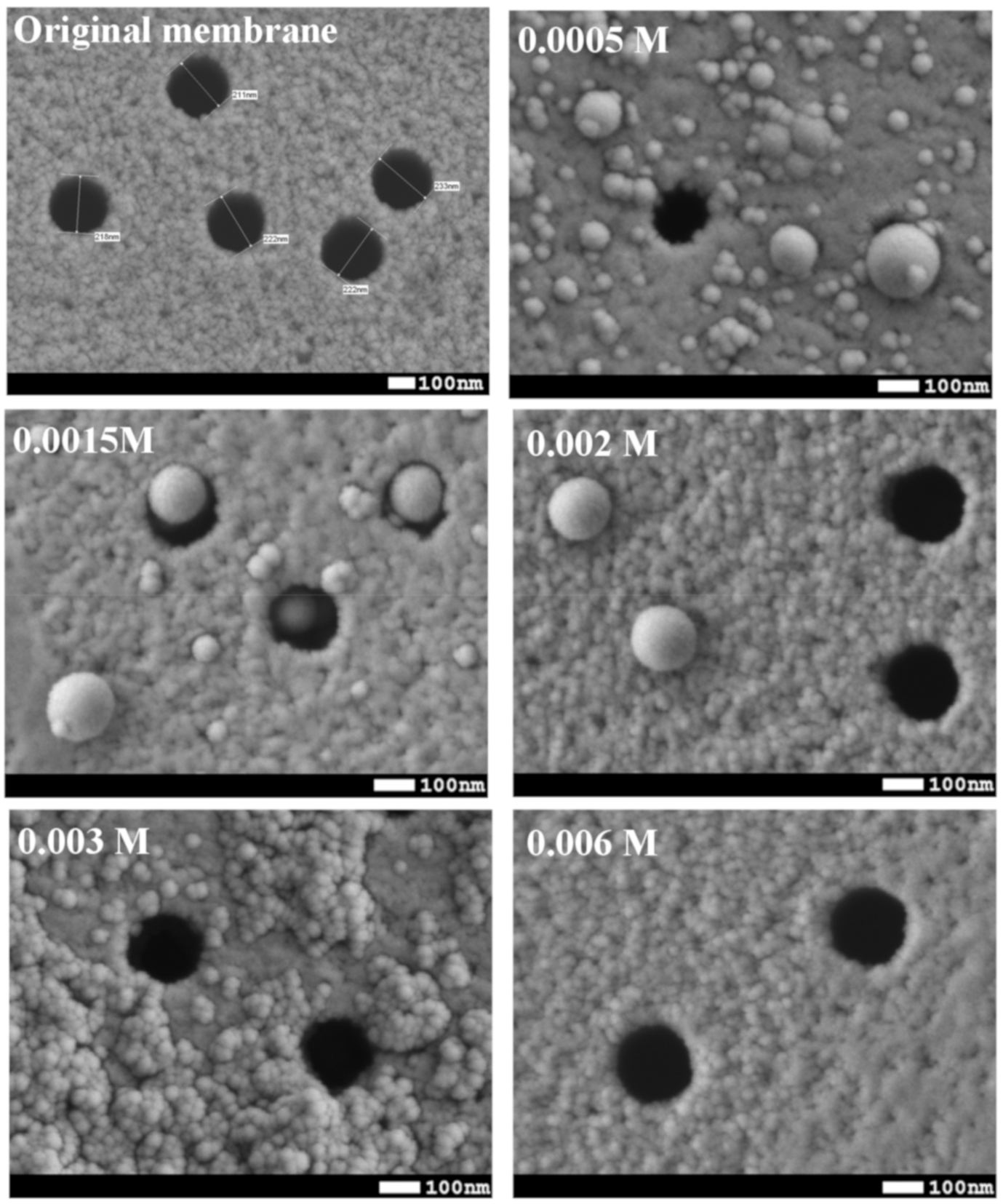
3.1. Synthesis of Silica Nanoparticles
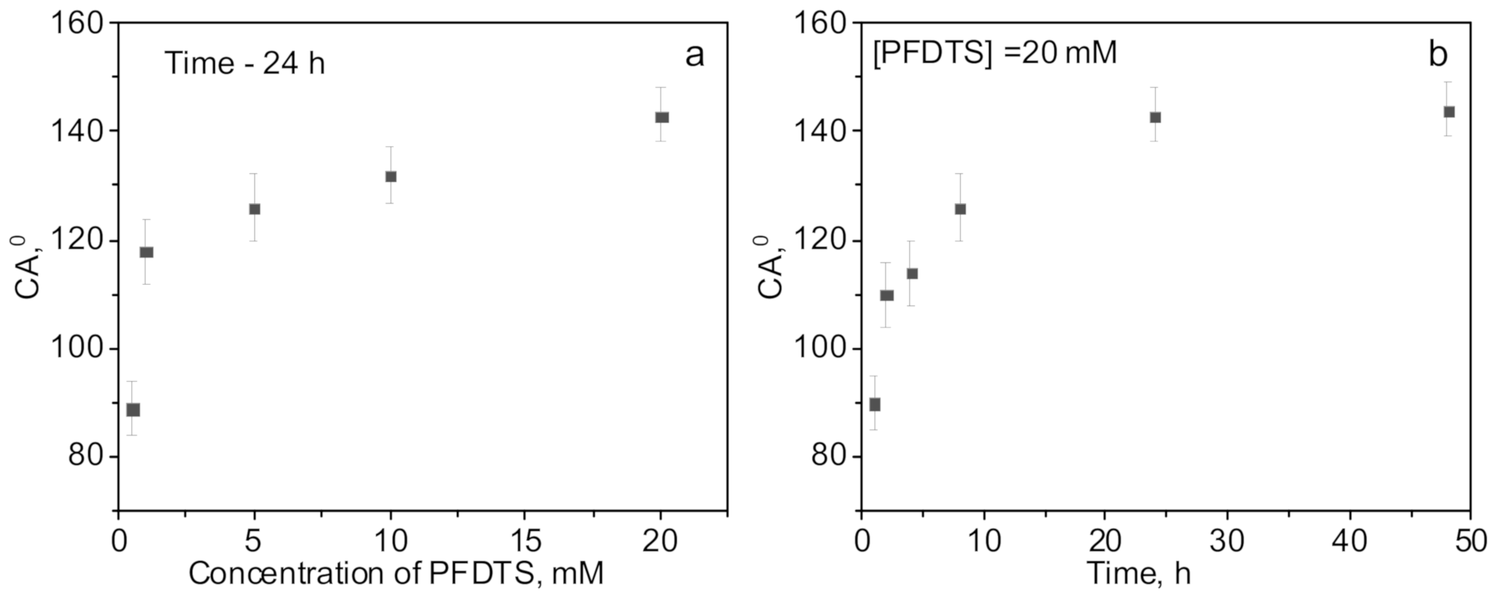
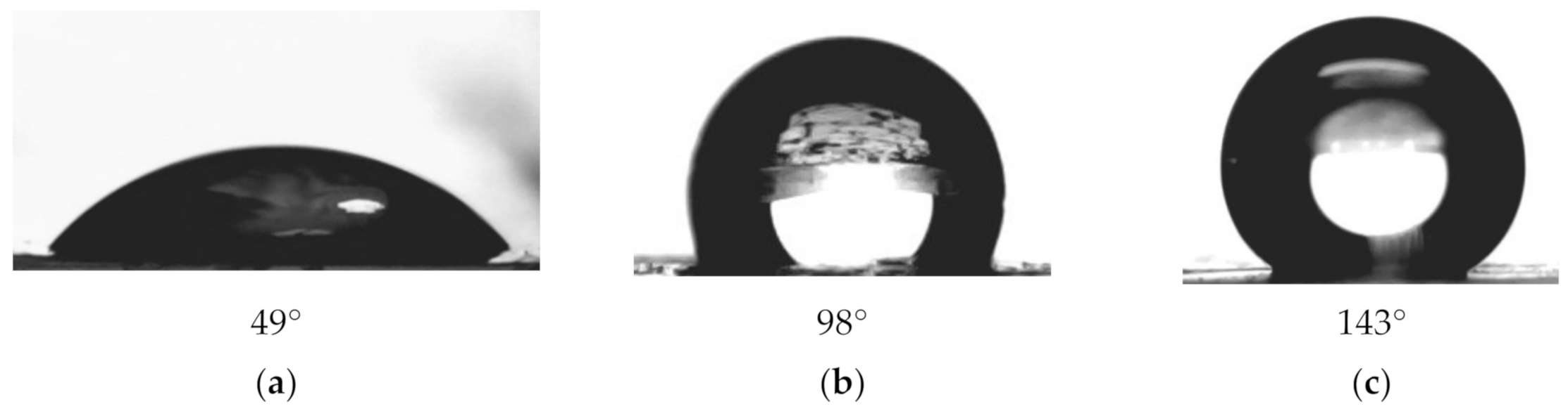
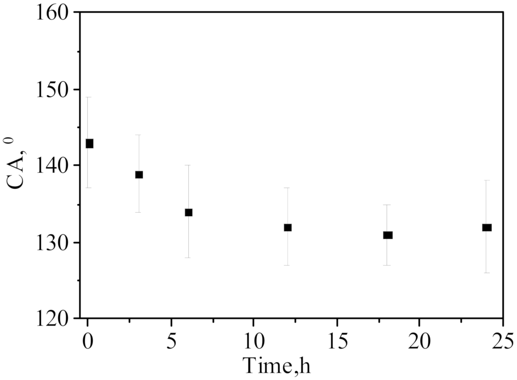
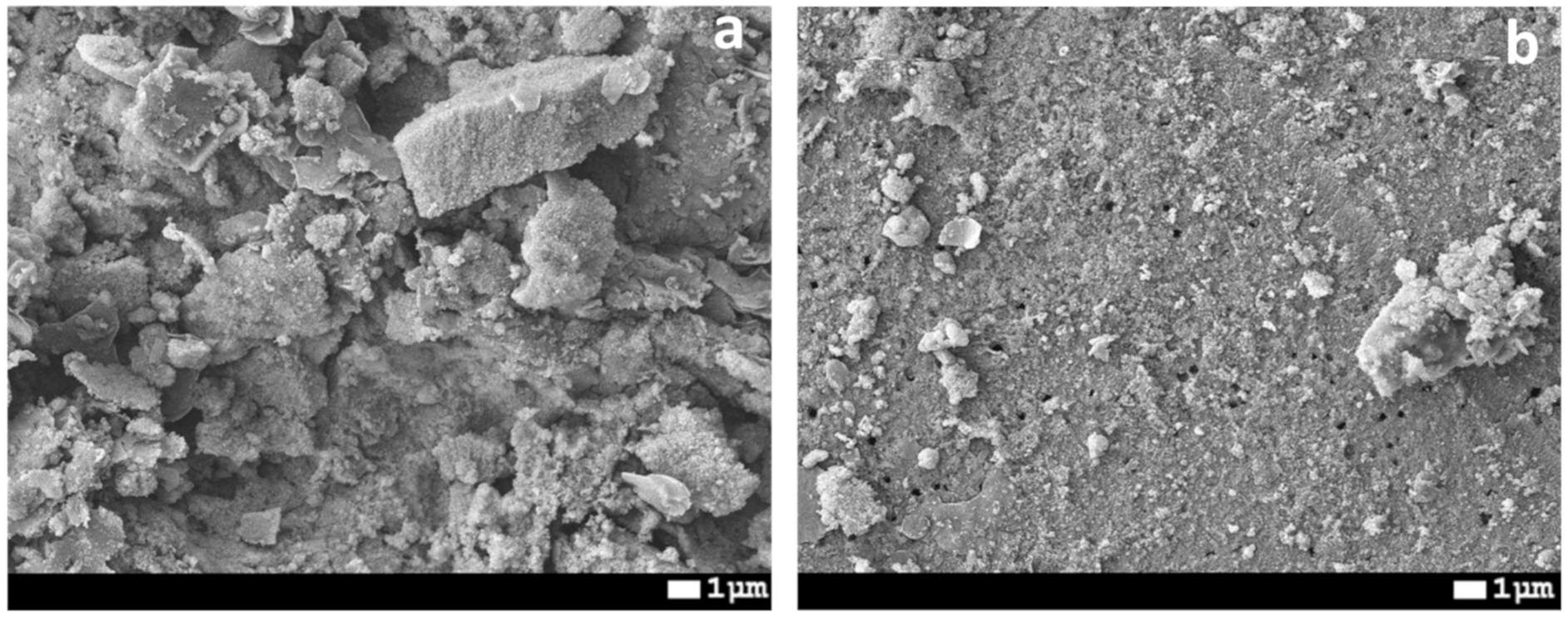
3.2. Preparation of Hydrophobic Membrane
3.3. Membrane Distillation
4. Conclusions
Author Contributions
Funding
Conflicts of Interest
References
- FAO. Coping with Water Scarcity An Action Framework for Agriculture and Food Security; FAO: Rome, Italy, 2012. [Google Scholar]
- Water Scarcity. Available online: https://www.un.org/waterforlifedecade/scarcity.shtml (accessed on 1 August 2020).
- González, D.; Amigo, J.; Suárez, F. Membrane distillation: Perspectives for sustainable and improved desalination. Renew. Sustain. Energy Rev. 2017, 80, 238–259. [Google Scholar] [CrossRef]
- Hamzah, N.; Leo, C.P. Fouling prevention in the membrane distillation of phenolic-rich solution using superhydrophobic PVDF membrane incorporated with TiO2 nanoparticles. Sep. Purif. Technol. 2016, 167, 79–87. [Google Scholar] [CrossRef]
- Hubadillah, S.K.; Tai, Z.S.; Othman, M.H.D.; Harun, Z.; Jamalludin, M.R.; Rahman, M.A.; Jaafar, J.; Ismail, A.F. Hydrophobic ceramic membrane for membrane distillation: A mini review on preparation, characterization, and applications. Sep. Purif. Technol. 2019, 217, 71–84. [Google Scholar] [CrossRef]
- Siyal, M.I.; Lee, C.K.; Park, C.; Khan, A.A.; Kim, J.O. A review of membrane development in membrane distillation for emulsified industrial or shale gas wastewater treatments with feed containing hybrid impurities. J. Environ. Manag. 2019, 243, 45–66. [Google Scholar] [CrossRef] [PubMed]
- Foureaux, A.F.S.; Moreira, V.R.; Lebron, Y.A.R.; Santos, L.V.S.; Amaral, M.C.S. Direct contact membrane distillation as an alternative to the conventional methods for value-added compounds recovery from acidic effluents: A review. Sep. Purif. Technol. 2019, 236, 116251. [Google Scholar] [CrossRef]
- Naidu, G.; Tijing, L.; Johir, M.A.H.; Shon, H.; Vigneswaran, S. Hybrid membrane distillation: Resource, nutrient and energy recovery. J. Membr. Sci. 2020, 599, 117832. [Google Scholar] [CrossRef]
- Ashoor, B.B.; Mansour, S.; Giwa, A.; Dufour, V.; Hasan, S.W. Principles and applications of direct contact membrane distillation (DCMD): A comprehensive review. Desalination 2016, 398, 222–246. [Google Scholar] [CrossRef]
- Cassard, H.M.; Park, H.G. How to select the optimal membrane distillation system for industrial applications. J. Membr. Sci. 2018, 565, 402–410. [Google Scholar] [CrossRef]
- Korolkov, I.V.; Yeszhanov, A.B.; Gorin, Y.G.; Zdorovets, M.V. Hydrophobization of PET track-etched membranes for direct contact membrane distillation. Mater. Res. Express 2018, 5, 065317. [Google Scholar] [CrossRef]
- Song, L.; Li, B.; Sirkar, K.K.; Gilron, J.L. Direct Contact Membrane Distillation-Based Desalination: Novel Membranes, Devices, Larger-Scale Studies, and a Model. Ind. Eng. Chem. Res. 2007, 46, 2307–2323. [Google Scholar] [CrossRef]
- Subramanian, N.; Qamar, A.; Alsaadi, A.; Gallo, A.; Ridwan, M.G.; Lee, J.-G.; Pillai, S.; Arunachalam, S.; Anjum, D.; Sharipov, F.; et al. Evaluating the potential of superhydrophobic nanoporous alumina membranes for direct contact membrane distillation. J. Colloid Interface Sci. 2019, 533, 723–732. [Google Scholar] [CrossRef] [PubMed]
- Shirazi, M.M.A.; Kargari, A.; Tabatabaei, M. Evaluation of commercial PTFE membranes in desalination by direct contact membrane distillation. Chem. Eng. Process. Process Intensif. 2014, 76, 16–25. [Google Scholar] [CrossRef]
- Zuo, J.; Bonyadi, S.; Chung, T.S. Exploring the potential of commercial polyethylene membranes for desalination by membrane distillation. J. Membr. Sci. 2016, 497, 239–247. [Google Scholar] [CrossRef]
- McGaughey, A.L.; Gustafson, R.D.; Childress, A.E. Effect of long-term operation on membrane surface characteristics and performance in membrane distillation. J. Membr. Sci. 2017, 543, 143–150. [Google Scholar] [CrossRef]
- Banat, F.A.; Simandl, J. Desalination by Membrane Distillation: A Parametric Study. Sep. Sci. Technol. 1998, 33, 201–226. [Google Scholar] [CrossRef]
- Larbot, A.; Gazagnes, L.; Krajewski, S.; Bukowska, M. Wojciech Kujawski Water desalination using ceramic membrane distillation. Desalination 2004, 168, 367–372. [Google Scholar] [CrossRef]
- Alklaibi, A.M.; Lior, N. Membrane-distillation desalination: Status and potential. Desalination 2005, 171, 111–131. [Google Scholar] [CrossRef]
- Jia, F.; Yin, Y.; Wang, J. Removal of cobalt ions from simulated radioactive wastewater by vacuum membrane distillation. Prog. Nucl. Energy 2018, 103, 20–27. [Google Scholar] [CrossRef]
- Jia, F.; Li, J.; Wang, J.; Sun, Y. Removal of strontium ions from simulated radioactive wastewater by vacuum membrane distillation. Ann. Nucl. Energy 2017, 103, 363–368. [Google Scholar] [CrossRef]
- Lou, X.Y.; Ji, Z.G.; Xu, Z.; Bai, A.P.; Resina-Gallego, M. Separation and recycling of concentrated heavy metal wastewater by tube membrane distillation integrated with crystallization. Membranes 2020, 10, 19. [Google Scholar] [CrossRef]
- Criscuoli, A.; Zhong, J.; Figoli, A.; Carnevale, M.C.; Huang, R.; Drioli, E. Treatment of dye solutions by vacuum membrane distillation. Water Res. 2008, 42, 5031–5037. [Google Scholar] [CrossRef] [PubMed]
- Khumalo, N.P.; Nthunya, L.N.; De Canck, E.; Derese, S.; Verliefde, A.R.; Kuvarega, A.T.; Mamba, B.B.; Mhlanga, S.D.; Dlamini, D.S. Congo red dye removal by direct membrane distillation using PVDF/PTFE membrane. Sep. Purif. Technol. 2019, 211, 578–586. [Google Scholar] [CrossRef]
- Zakrzewska-Trznadel, G. Advances in membrane technologies for the treatment of liquid radioactive waste. Desalination 2013, 321, 119–130. [Google Scholar] [CrossRef]
- Rana, D.; Matsuura, T.; Kassim, M.A.; Ismail, A.F. Radioactive decontamination of water by membrane processes—A review. Desalination 2013, 321, 77–92. [Google Scholar] [CrossRef]
- Korolkov, I.V.; Yeszhanov, A.B.; Zdorovets, M.V.; Gorin, Y.G.; Güven, O.; Dosmagambetova, S.S.; Khlebnikov, N.A.; Serkov, K.V.; Krasnopyorova, M.V.; Milts, O.S.; et al. Modification of PET ion track membranes for membrane distillation of low-level liquid radioactive wastes and salt solutions. Sep. Purif. Technol. 2019, 227, 115694. [Google Scholar] [CrossRef]
- Zdorovets, M.V.; Yeszhanov, A.B.; Korolkov, I.V.; Güven, O.; Dosmagambetova, S.S.; Shlimas, D.I.; Zhatkanbayeva, Z.K.; Zhidkov, I.S.; Kharkin, P.V.; Gluchshenko, V.N.; et al. Liquid low-level radioactive wastes treatment by using hydrophobized track-etched membranes. Prog. Nucl. Energy 2020, 118, 103128. [Google Scholar] [CrossRef]
- Elkina, I.B.; Gilman, A.B.; Ugrozov, V.V.; Volkov, V.V. Separation of mineral acid solutions by membrane distillation and thermopervaporation through porous and nonporous membranes. Ind. Eng. Chem. Res. 2013, 52, 8856–8863. [Google Scholar] [CrossRef]
- Criscuoli, A.; Capuano, A.; Andreucci, M.; Drioli, E. Low-temperature direct contact membrane distillation for the treatment of aqueous solutions containing urea. Membranes 2020, 10, 176. [Google Scholar] [CrossRef]
- Reis, B.G.; Araújo, A.L.B.; Amaral, M.C.S.; Ferraz, H.C. Comparison of Nanofiltration and Direct Contact Membrane Distillation as an alternative for gold mining effluent reclamation. Chem. Eng. Process. Process Intensif. 2018, 133, 24–33. [Google Scholar] [CrossRef]
- Wijekoon, K.C.; Hai, F.I.; Kang, J.; Price, W.E.; Cath, T.Y.; Nghiem, L.D. Rejection and fate of trace organic compounds (TrOCs) during membrane distillation. J. Membr. Sci. 2014, 453, 636–642. [Google Scholar] [CrossRef]
- Eykens, L.; De Sitter, K.; Dotremont, C.; Pinoy, L.; Van der Bruggen, B. Membrane synthesis for membrane distillation: A review. Sep. Purif. Technol. 2017, 182, 36–51. [Google Scholar] [CrossRef]
- Wang, P.; Chung, T.-S. Recent advances in membrane distillation processes: Membrane development, configuration design and application exploring. J. Membr. Sci. 2015, 474, 39–56. [Google Scholar] [CrossRef]
- Singh, D.; Sirkar, K.K. Performance of PVDF Flat Membranes and Hollow Fibers in Desalination by Direct Contact Membrane Distillation at High Temperatures. Sep. Purif. Technol. 2017, 187, 264–273. [Google Scholar] [CrossRef]
- Zhao, D.; Zuo, J.; Lu, K.-J.; Chung, T.-S. Fluorographite modified PVDF membranes for seawater desalination via direct contact membrane distillation. Desalination 2017, 413, 119–126. [Google Scholar] [CrossRef]
- Zhang, Y.; Wang, X.; Cui, Z.; Drioli, E.; Wang, Z.; Zhao, S. Enhancing wetting resistance of poly(vinylidene fluoride) membranes for vacuum membrane distillation. Desalination 2017, 415, 58–66. [Google Scholar] [CrossRef]
- Panwar, V.; Lee, C.; Ko, S.Y.; Park, J.O.; Park, S. Dynamic mechanical, electrical, and actuation properties of ionic polymer metal composites using PVDF/PVP/PSSA blend membranes. Mater. Chem. Phys. 2012, 135, 928–937. [Google Scholar] [CrossRef]
- Khayet, M. Membranes and theoretical modeling of membrane distillation: A review. Adv. Colloid Interface Sci. 2011, 164, 56–88. [Google Scholar] [CrossRef]
- Naidu, G.; Jeong, S.; Vigneswaran, S.; Hwang, T.M.; Choi, Y.J.; Kim, S.H. A review on fouling of membrane distillation. Desalin. Water Treat. 2016, 57, 10052–10076. [Google Scholar] [CrossRef]
- Khayet, M.S.; Matsuura, T. Membrane Distillation: Principles and Applications; Elsevier: Amsterdam, The Netherlands, 2011; ISBN 9780444531261. [Google Scholar]
- Wang, X.; Yu, J.; Sun, G.; Ding, B. Electrospun nanofibrous materials: A versatile medium for effective oil/water separation. Mater. Today 2016, 19, 403–414. [Google Scholar] [CrossRef]
- Hou, D.; Lin, D.; Ding, C.; Wang, D.; Wang, J. Fabrication and characterization of electrospun superhydrophobic PVDF-HFP/SiNPs hybrid membrane for membrane distillation. Sep. Purif. Technol. 2017, 189, 82–89. [Google Scholar] [CrossRef]
- Li, X.; García-Payo, M.C.; Khayet, M.; Wang, M.; Wang, X. Superhydrophobic polysulfone/polydimethylsiloxane electrospun nanofibrous membranes for water desalination by direct contact membrane distillation. J. Membr. Sci. 2017, 542, 308–319. [Google Scholar] [CrossRef]
- Korolkov, I.V.; Gorin, Y.G.; Yeszhanov, A.B.; Kozlovskiy, A.L.; Zdorovets, M.V. Preparation of PET track-etched membranes for membrane distillation by photo-induced graft polymerization. Mater. Chem. Phys. 2018, 205, 55–63. [Google Scholar] [CrossRef]
- Cui, Z.; Drioli, E.; Lee, Y.M. Recent progress in fluoropolymers for membranes. Prog. Polym. Sci. 2014, 39, 164–198. [Google Scholar] [CrossRef]
- Barsbay, M.; Güven, O. Grafting in confined spaces: Functionalization of nanochannels of track-etched membranes. Radiat. Phys. Chem. 2014, 105, 26–30. [Google Scholar] [CrossRef]
- Kong, Y.; Lin, X.; Wu, Y.; Chen, J.; Xu, J. Plasma polymerization of octafluorocyclobutane and hydrophobic microporous composite membranes for membrane distillation. J. Appl. Polym. Sci. 1992, 46, 191–199. [Google Scholar] [CrossRef]
- Wu, Y.; Kong, Y.; Lin, X.; Liu, W.; Xu, J. Surface-modified hydrophilic membranes in membrane distillation. J. Membr. Sci. 1992, 72, 189–196. [Google Scholar] [CrossRef]
- Elmarghany, M.R.; El-Shazly, A.H.; Rajabzadeh, S.; Salem, M.S.; Shouman, M.A.; Sabry, M.N.; Matsuyama, H.; Nady, N. Triple-layer nanocomposite membrane prepared by electrospinning based on modified PES with carbon nanotubes for membrane distillation applications. Membranes 2020, 10, 15. [Google Scholar] [CrossRef]
- Xiao, Z.; Guo, H.; He, H.; Liu, Y.; Li, X.; Zhang, Y.; Yin, H.; Volkov, A.V.; He, T. Unprecedented scaling/fouling resistance of omniphobic polyvinylidene fluoride membrane with silica nanoparticle coated micropillars in direct contact membrane distillation. J. Membr. Sci. 2020, 599, 117819. [Google Scholar] [CrossRef]
- Li, J.; Guo, S.; Xu, Z.; Li, J.; Pan, Z.; Du, Z.; Cheng, F. Preparation of omniphobic PVDF membranes with silica nanoparticles for treating coking wastewater using direct contact membrane distillation: Electrostatic adsorption vs. chemical bonding. J. Membr. Sci. 2019, 574, 349–357. [Google Scholar] [CrossRef]
- Hou, D.; Christie, K.S.S.; Wang, K.; Tang, M.; Wang, D.; Wang, J. Biomimetic superhydrophobic membrane for membrane distillation with robust wetting and fouling resistance. J. Membr. Sci. 2019, 599, 117708. [Google Scholar] [CrossRef]
- Ma, T.; Janot, J.; Balme, S. Track-Etched Nanopore/Membrane: From Fundamental to Applications. Small Methods 2020, 4, 2000366. [Google Scholar] [CrossRef]
- Gancarz, I.; Bryjak, M.; Kujawski, J.; Wolska, J.; Kujawa, J.; Kujawski, W. Plasma deposited fluorinated films on porous membranes. Mater. Chem. Phys. 2015, 151, 233–242. [Google Scholar] [CrossRef]
- Effati, E.; Pourabbas, B. One-pot synthesis of sub-50nm vinyl- and acrylate-modified silica nanoparticles. Powder Technol. 2012, 219, 276–283. [Google Scholar] [CrossRef]
- Golshaei, P.; Güven, O. Chemical modification of PET surface and subsequent graft copolymerization with poly(N-isopropylacrylamide). React. Funct. Polym. 2017, 118, 26–34. [Google Scholar] [CrossRef]
- Korolkov, I.V.; Mashentseva, A.A.; Gueven, O.; Niyazova, D.T.; Barsbay, M.; Zdorovets, M. V The effect of oxidizing agents/systems on the properties of track-etched PET membranes. Polym. Degrad. Stab. 2014, 107, 150–157. [Google Scholar] [CrossRef]
- Roux, S.; Demoustier-Champagne, S. Surface-initiated polymerization from poly(ethylene terephthalate). J. Polym. Sci. Part A Polym. Chem. 2003, 41, 1347–1359. [Google Scholar] [CrossRef]
- Mulder, M. Transport in Membranes. In Basic Principles of Membrane Technology; Springer: Dordrecht, The Netherlands, 1996; pp. 210–279. [Google Scholar]
- Ahmed, F.E.; Lalia, B.S.; Hashaikeh, R. Membrane-based detection of wetting phenomenon in direct contact membrane distillation. J. Membr. Sci. 2017, 535, 89–93. [Google Scholar] [CrossRef]
- García-Payo, M.C.; Izquierdo-Gil, M.A.; Fernández-Pineda, C. Wetting Study of Hydrophobic Membranes via Liquid Entry Pressure Measurements with Aqueous Alcohol Solutions. J. Colloid Interface Sci. 2000, 230, 420–431. [Google Scholar] [CrossRef]
- Chamani, H.; Yazgan-Birgi, P.; Matsuura, T.; Rana, D.; Hassan Ali, M.I.; Arafat, H.A.; Lan, C.Q. CFD-based genetic programming model for liquid entry pressure estimation of hydrophobic membranes. Desalination 2020, 476, 114231. [Google Scholar] [CrossRef]
- Xu, J.; Li, M.; Zhao, Y.; Lu, Q. Control over the hydrophobic behavior of polystyrene surface by annealing temperature based on capillary template wetting method. Colloids Surfaces A Physicochem. Eng. Asp. 2007, 302, 136–140. [Google Scholar] [CrossRef]
- Arkles, B. Hydrophobicity, Hydrophilicity and Silane Surface Modification; Gelest: Derbyshire, UK, 2015; Volume 1, ISBN 9788578110796. [Google Scholar]
- Rahman, I.A.; Padavettan, V. Synthesis of Silica nanoparticles by Sol-Gel: Size-dependent properties, surface modification, and applications in silica-polymer nanocompositesa review. J. Nanomater. 2012, 2012, 132424. [Google Scholar] [CrossRef]
- Kutuzau, M.; Kozlovskiy, A.; Borgekov, D.; Kenzhina, I.; Zdorovets, M.; Chernik, A.; Alisienok, O.; Shumskaya, A.; Kaniukov, E. Optimization of PET Ion-Track Membranes Parameters. Mater. Today Proc. 2019, 7, 866–871. [Google Scholar] [CrossRef]
- Donelli, I.; Freddi, G.; Nierstrasz, V.A.; Taddei, P. Surface structure and properties of poly-(ethylene terephthalate) hydrolyzed by alkali and cutinase. Polym. Degrad. Stab. 2010, 95, 1542–1550. [Google Scholar] [CrossRef]
- Bae, G.Y.; Jang, J.; Jeong, Y.G.; Lyoo, W.S.; Min, B.G. Superhydrophobic PLA fabrics prepared by UV photo-grafting of hydrophobic silica particles possessing vinyl groups. J. Colloid Interface Sci. 2010, 344, 584–587. [Google Scholar] [CrossRef] [PubMed]
- Doren, A.; Genet, M.J.; Rouxhet, P.G. Analysis of Poly(Ethylene Terephthalate) (PET) by XPS. Surf. Sci. Spectra 1994, 3, 337–341. [Google Scholar] [CrossRef]
- Browne, M.M.; Lubarsky, G.V.; Davidson, M.R.; Bradley, R.H. Protein adsorption onto polystyrene surfaces studied by XPS and AFM. Surf. Sci. 2004, 553, 155–167. [Google Scholar] [CrossRef]
- Nakayama, Y.; Takahagi, T.; Soeda, F.; Ishitani, A.; Kosugi, N.; Kuroda, H. A study of XPS O1s spectrum of poly(ethylene terephthalate). J. Polym. Sci. Part A Polym. Chem. 1990, 28, 1813–1821. [Google Scholar] [CrossRef]
- Wang, H.; Zhou, H.; Gestos, A.; Fang, J.; Niu, H.; Ding, J.; Lin, T. Robust, electro-conductive, self-healing superamphiphobic fabric prepared by one-step vapour-phase polymerisation of poly(3,4-ethylenedioxythiophene) in the presence of fluorinated decyl polyhedral oligomeric silsesquioxane and fluorinated alkyl silane. Soft Matter 2013, 9, 277–282. [Google Scholar] [CrossRef]
- Lagutchev, A.S.; Song, K.J.; Huang, J.Y.; Yang, P.K.; Chuang, T.J. Self-assembly of alkylsiloxane monolayers on fused silica studied by XPS and sum frequency generation spectroscopy. Chem. Phys. 1998, 226, 337–349. [Google Scholar] [CrossRef]
- Fleury, M.; Deschamps, H. Viscosity and Electrical Conductivity of Aqueous NaCl Solutions with Dissolved CO2. Energy Procedia 2009, 1, 3129–3133. [Google Scholar] [CrossRef][Green Version]
- Tirado, M.; Grosse, C. Conductivity dependence of the polarization impedance spectra of platinum black electrodes in contact with aqueous NaCl electrolyte solutions. Colloids Surfaces A Physicochem. Eng. Asp. 2003, 222, 293–299. [Google Scholar] [CrossRef]
- Gryta, M.; Tomaszewska, M.; Karakulski, K. Wastewater treatment by membrane distillation. Desalination 2006, 198, 67–73. [Google Scholar] [CrossRef]
- Yang, Y.; Liu, Q.; Wang, H.; Ding, F.; Jin, G.; Li, C.; Meng, H. Superhydrophobic modification of ceramic membranes for vacuum membrane distillation. Chin. J. Chem. Eng. 2017, 25, 1395–1401. [Google Scholar] [CrossRef]
- Wang, R.; Shi, L.; Tang, C.Y.; Chou, S.; Qiu, C.; Fane, A.G. Characterization of novel forward osmosis hollow fiber membranes. J. Membr. Sci. 2010, 355, 158–167. [Google Scholar] [CrossRef]


| Concentration of Surfactant, M | CA *, ° |
|---|---|
| 0.0005 | 117 ± 6 |
| 0.0008 | 114 ± 6 |
| 0.0015 | 109 ± 4 |
| 0.002 | 98 ± 5 |
| 0.003 | 98 ± 5 |
| 0.006 | 71 ± 5 |
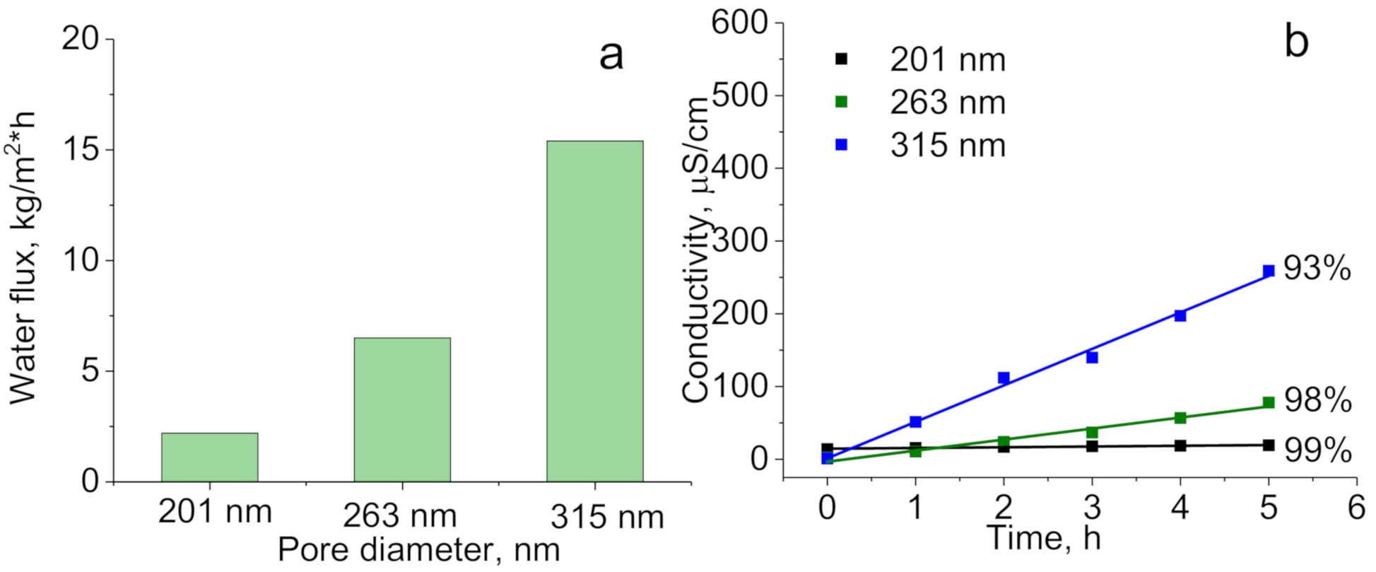
| Sample | Contact Angle, ° | Effective Pore Diameter, nm | LEPexp, Bar | LEPGP-CFD Model, Bar |
|---|---|---|---|---|
| Original PET membrane | 49 ± 5 | 247 ± 5 | - | - |
| PET-ABAP membrane | 54 ± 6 | 247 ± 4 | - | - |
| PET-Si membrane | 98 ± 5 | 167 ± 6 | 3.2 | 3.4 |
| PET Si-F membrane | 143 ± 6 | 152 ± 6 | > 4.3 | 9.7 |
| PET Si-F membrane * | 135 ± 6 | 201 ± 5 | > 4.3 | 6.4 |
| PET Si-F membrane ** | 132 ± 5 | 263 ± 5 | 4.1 | 4.3 |
| PET Si-F membrane *** | 125 ± 5 | 315 ± 6 | 3.5 | 3.4 |
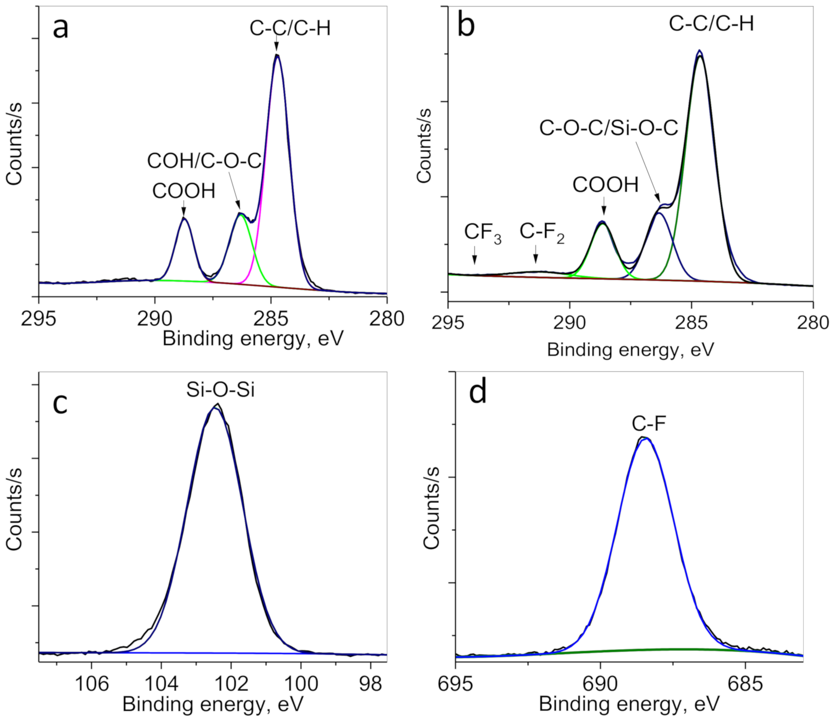
| Sample | Atomic Concentration, % | High Resolution C1s Moieties, % | ||||||||
|---|---|---|---|---|---|---|---|---|---|---|
| C | O | N | Si | F | C-C/C-H | Si-O-C/C-O-C | C = O | C-F2 | C-F3 | |
| Original PET membranes | 72.5 | 27.5 | - | - | - | 66.1 | 19.8 | 14.1 | - | - |
| PET-ABAP membranes | 75.1 | 22.3 | 2.6 | - | - | 66.8 | 19.4 | 13.8 | - | - |
| PET- Si membranes | 63.9 | 27.9 | 0.8 | 4.1 | - | 67.1 | 18.9 | 14 | - | - |
| PET-Si-F membranes | 63.9 | 27.9 | - | 5.7 | 2.5 | 64.6 | 19.0 | 13.5 | 1.6 | 0.3 |
Publisher’s Note: MDPI stays neutral with regard to jurisdictional claims in published maps and institutional affiliations. |
© 2020 by the authors. Licensee MDPI, Basel, Switzerland. This article is an open access article distributed under the terms and conditions of the Creative Commons Attribution (CC BY) license (http://creativecommons.org/licenses/by/4.0/).
Share and Cite
Korolkov, I.V.; Kuandykova, A.; Yeszhanov, A.B.; Güven, O.; Gorin, Y.G.; Zdorovets, M.V. Modification of PET Ion-Track Membranes by Silica Nanoparticles for Direct Contact Membrane Distillation of Salt Solutions. Membranes 2020, 10, 322. https://doi.org/10.3390/membranes10110322
Korolkov IV, Kuandykova A, Yeszhanov AB, Güven O, Gorin YG, Zdorovets MV. Modification of PET Ion-Track Membranes by Silica Nanoparticles for Direct Contact Membrane Distillation of Salt Solutions. Membranes. 2020; 10(11):322. https://doi.org/10.3390/membranes10110322
Chicago/Turabian StyleKorolkov, Ilya V., Azhar Kuandykova, Arman B. Yeszhanov, Olgun Güven, Yevgeniy G. Gorin, and Maxim V. Zdorovets. 2020. "Modification of PET Ion-Track Membranes by Silica Nanoparticles for Direct Contact Membrane Distillation of Salt Solutions" Membranes 10, no. 11: 322. https://doi.org/10.3390/membranes10110322
APA StyleKorolkov, I. V., Kuandykova, A., Yeszhanov, A. B., Güven, O., Gorin, Y. G., & Zdorovets, M. V. (2020). Modification of PET Ion-Track Membranes by Silica Nanoparticles for Direct Contact Membrane Distillation of Salt Solutions. Membranes, 10(11), 322. https://doi.org/10.3390/membranes10110322