Abstract
Nanocomposite sodalite/ceramic membranes supported on α-Al2O3 tubular support were prepared via the pore-plugging hydrothermal (PPH) synthesis protocol using one interruption and two interruption steps. In parallel, thin-film membranes were prepared via the direct hydrothermal synthesis technique. The as-synthesized membranes were evaluated for H2/CO2 separation in the context of pre-combustion CO2 capture. Scanning electron microscopy (SEM) was used to check the surface morphology while x-ray diffraction (XRD) was used to check the crystallinity of the sodalite crystals and as-synthesized membranes. Single gas permeation of H2, CO2, N2 and mixture gas H2/CO2 was used to probe the quality of the membranes. Gas permeation results revealed nanocomposite membrane prepared via the PPH synthesis protocols using two interruption steps displayed the best performance. This was attributed to the enhanced pore-plugging effect of sodalite crystals in the pores of the support after the second interruption step. The nanocomposite membrane displayed H2 permeance of 7.97 × 10⁻⁷ mol·s−1·m−2·Pa−1 at 100 °C and 0.48 MPa feed pressure with an ideal selectivity of 8.76. Regarding H2/CO2 mixture, the H2 permeance reduced from 8.03 × 10⁻⁷ mol·s−1·m−2·Pa−1 to 1.06 × 10⁻⁷ mol·s−1·m−2·Pa−1 at 25 °C and feed pressure of 0.18 MPa. In the presence of CO2, selectivity of the nanocomposite membrane reduced to 4.24.
1. Introduction
The application of inorganic membranes for liquid separation and evaporation have proven to be energy-efficient and have demonstrated good stability in the presence of water [1,2,3,4]. According to Li et al. [5], inorganic membranes have the potential to invade territories currently occupied by existing technology like absorption. Hence, these class of membranes are attracting great interest as molecular sieves membranes and are therefore being explored and developed for gas separations. Inorganic membranes are well adapted and promising to perform intrinsic difficult separation such as pre-combustion CO2 capture (H2/CO2 separation) [6,7,8]. Ultimately, the industrial application of inorganic membranes for gas separation in an integrated gasification combined cycle plants could fast track the goal of process intensification in such plants.
Zeolite membranes prepared by growing a thin selective zeolite layer referred to as “thin-film” on top of a support via the direct hydrothermal synthesis method [9,10,11,12,13] and via the secondary-seeded growth method [14,15,16,17] are well reported and have produced good membranes. However, when membranes prepared by these techniques are subjected to large temperature changes, thermal expansion mismatch between the membrane layer and support often leads to grain boundary opening and build-up of long-range stresses [18,19]. As a result, non-selective transport pathways for permeating molecules are created which impacts the performance of the membrane negatively [20,21,22]. To overcome this shortcoming, the pore-plugging hydrothermal (PPH) synthesis was proposed to synthesize quality zeolite membranes [23,24]. In this technique, the zeolite particles are embedded within the pores of the support by temporarily withdrawing the autoclave from the oven during synthesis. By so doing, the expansion of crystals is limited to the pore size of the support [19,25,26,27]. Julbe et al. [28] and Li et al. [23] acknowledged that although, the internal layer of an infiltrated support could contribute to resisting gas transport, the nanocomposite layer is not susceptible to defects, has higher thermal shock resistance, can provide improved membrane separation performance compared to thin-film or surface layer membrane. These qualities are highly attractive for applications in high-temperature environments such as the case in pre-combustion CO2 capture.
Hydroxy sodalite (HSOD) zeolite belongs to the sodalite family and it is formed by connecting sodalite (SOD) cages through common 4- and 6-ring [29,30,31]. The concept for the mechanism of separation of H2 from H2/CO2 mixture using sodalite membrane is highlighted by the size of the SOD aperture relative to the kinetic diameter of H2 and CO2 shown in Figure 1.
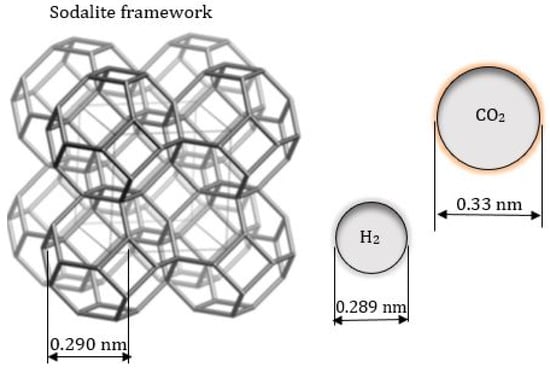
Figure 1.
Relative size of SOD structure compared to the kinetic diameter of H2 and CO2 molecule. HSOD structure adapted from Treacy and Higgins [32] and H2 and CO2 diameter from Jansen et al. [33] and Xu et al. [34].
According to Daramola et al. [35], the challenge with developing zeolite membranes via the PPH technique is to reproducibly synthesize high-quality, defect-free supported membranes with high permeance while maintaining high H2/CO2 selectivity. Also, the number of reports on supported sodalite membranes prepared via the PPH technique focusing on gas separation especially H2/CO2 separation is still very limited. Daramola et al. [36,37] synthesized nanocomposite hydroxy sodalite (HSOD) ceramic membranes via the PPH technique but the gas permeation measurement and capability of the membrane to sieve molecules was not investigated. Oloye et al. [38] reported the procedure developed by Daramola et al. [36,37] in preparing nanocomposite sodalite (SOD)/ceramic membrane via one-stage and two-stage PPH synthesis. The authors reported SOD fully plugged the 200 nm layer of the α-alumina ceramic support and the nanocomposite SOD/ceramic membrane prepared was moderately selective towards hydrogen as confirmed by SEM. However, the authors did not conduct mixture gas separation test, hence, no information about the real selectivity of the membrane was reported. Recently, Eterigho-Ikelegbe et al. [39] optimized the pore-plugging hydrothermal synthesis to produce quality zeolite crystals. Results revealed zeolite crystals produced using two interruption steps produced the highest quality crystals as confirmed by XRD, SEM, and FTIR.
Therefore, it seems justified to investigate the molecular sieving capability of SOD membrane prepared via the pore-plugging hydrothermal protocol using one interruption step and two interruption steps as reported in this study. Thin-film membranes synthesized via direct hydrothermal synthesis method (Teflon around the outer surface of the support) were also synthesized to compare results. Pure gas of H2, CO2, and mixture gas of H2/CO2 was used as evaluation criteria.
2. Materials and Methods
2.1. Materials
Anhydrous sodium aluminate (NaAl2O3), sodium metasilicate (Na2SiO3), and anhydrous sodium hydroxide (NaOH) were used as chemicals for the synthesis of sodalite (SOD) membrane. The chemicals were purchased from Sigma-Aldrich (Pty) (Modderfontein, South Africa) and used without further purification. Deionized water used in the synthesis was prepared in-house and the porous α-alumina (Al2O3) tubular supports was used without modifications. The tubular supports have an internal diameter of 7 mm and an external diameter of 10 mm with both ends coated with 1 mm non-porous surface for sealing in the module, making the total permeating length 13 cm.
2.2. Preparation of SOD Membranes
SOD membranes were prepared following a modified method of Miachon et al. [24] as reported by Daramola et al. [36]. A precursor solution of molar composition 5SiO2:0.5Al2O3:50Na2O:1005H2O and a pH of 14 was subjected to the pre-programmed temperature profiles shown in Figure 2. At the end of each synthesis, the hot autoclave was cooled under tap water to obtain the as-synthesized SOD membranes and SOD crystals formed at the bottom of the autoclave. Afterward, the membranes and crystals were washed using deionized water until the pH of the filtrate was 7, then dried at 100 °C overnight in an oven. Two membranes were synthesized for each hydrothermal synthesis protocol.
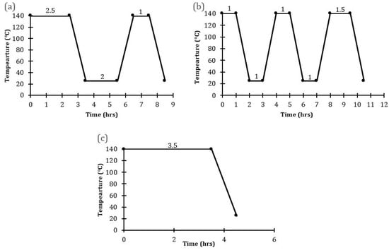
Figure 2.
Temperature profiles employed for the synthesis of SOD/α-Al2O3 (a) PPH with one interruption (Membranes M1, M2) (b) PPH with two interruptions (Membranes M3, M4) (c) direct hydrothermal synthesis (Membranes B1, B2).
2.3. Membrane Characterization
The crystallinity and purity of the as-synthesized SOD crystals and membranes were checked using x-ray diffractometer (XRD) (Bruker D2 phaser diffractometer equipped with Cu Kα radiation, λ = 1.54184 Å in the 2-theta range of 10–50 °C with a counting step of 31.4 s per step). A scanning electron microscope (FEI NovaLab 600 SEM, Johannesburg, South Africa) was used to check the morphology of the as-synthesized crystals and membrane surface.
2.4. Gas Permeation Measurements
The as-synthesized SOD membrane quality was evaluated using single gas (H2, N2, and CO2) permeation measurement and H2/CO2 binary mixtures (H2:CO2 = 60:40). The mixture ratio was chosen because it represents the H2 concentration expected in coal gasification after the water-gas-shift reaction. Before the permeation test, the membranes were thermally treated to a temperature of 100 °C to remove any absorbed moisture and other contaminants. The as-synthesized SOD/ceramic membrane was then gently placed inside a membrane module and held firm in the module using graphite O-rings seals, which also sealed the non-porous ends of the ceramic tube membrane to the membrane module. After setting the laboratory gas supplies from the cylinder to the desired pressure, forward pressure regulators were adjusted to tune individual gas inlet pressure. Thereafter, feed gas was fed to the tube side of the membrane in the module at a specific flow rate, pressure, and temperature. Permeate gas flowed through the shell side of the membrane for both single and mixture gas experiments. The test was conducted without sweep and permeate side pressure was kept at atmospheric pressure all through. The temperature of the feed gas was increased in small increments to avoid sudden overheating of the furnace and module. Permeation was measured as a function of pressure ranging from 0.1 MPa to 0.5 MPa and at a temperature ranging from 25 °C to 200 °C in the dead-end mode (i.e., retentate stream blocked) for single gas experiments. During the mixture gas experiment, the retentate stream (SOV 7) was left opened and controlled by a valve, the permeate stream was vented to the atmosphere, while SOV 5 remained locked (see Figure 3). To obtain consistency in data reporting under a set of experimental variables, at least one-hour equilibrium time was necessary for the system to reach steady-state. Also, the experimental test for each membrane was done twice to ensure reliable statistical average. A Bruker 430-GC gas chromatography equipped with a thermal conductivity detector (TCD) and coupled with stainless-steel column (2 m, OD:3.175 mm, ID:2 mm) was used to analyze the composition of the permeate streams. The gas composition in the retentate stream was not known, however, a mass balance was used to get retentate composition. Permeance Пi, ideal selectivity (Si/j), separation factor (SFi/j) was obtained using Equations (1)–(3), respectively.
where Fi is the flux of specie i through the membrane, fi is the molar flow rate of the gas, A is membrane, Pi,f and Pi,p are pressures of component i in the feed, and permeate sides, respectively, ΔPi is the trans-membrane pressure across the membrane of a gas component i, and are the permeance of pure gas feed i (H2) and feed j (CO2), respectively, y and x are the mole fraction of gas components on the permeate and feed side of the membrane.
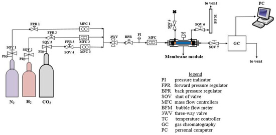
Figure 3.
Process Flow Diagram (PFD) of the permeation set-up employed for single and mixture gas permeation experiment.
3. Results and Discussion
3.1. Membrane Characterization
Sodalite crystals were recovered from the bottom of the autoclave after each of the membrane synthesis and were examined to confirm the purity of the SOD crystals that made the membrane via XRD analysis. The XRD patterns of SOD crystals obtained from M1 and M4 membrane depicted in Figure 4 reveal that the patterns of the synthesized SOD agree well with that of the simulated XRD pattern of SOD from the International Zeolite Association (IZA) [32], and also agree with other synthesized SOD crystals from literature [9,28,39,40,41,42]. Based on these observations, it is clear that the SOD crystals grown within the alumina to form the membrane are pure SOD crystals. On the other hand, the XRD patterns of SOD crystals obtained for membranes M2 and M3 contain some impurities which are other types of zeolites such as LTN, NaX, CAN, LTA, MOR. The crystallization of larger size zeolites led to higher porosity as will be discussed in Section 3.2. The presence of impurity phases i.e., phases that are not sodalite indicates qualitatively that membranes M2 and M3 were of very low quality. Very weak LTA peaks were observed on the XRD patterns of membrane B1 and B2, which might have been as a result of external influences in the laboratory they were not easy to control.
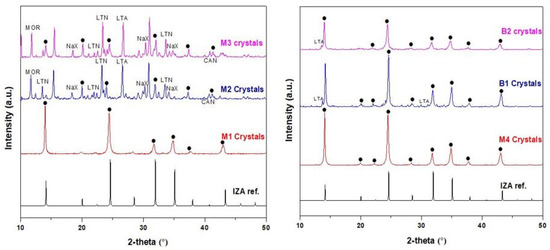
Figure 4.
XRD patterns of the crystals obtained from the bottom of the autoclave during the synthesis of membranes M1, M2, M3, M4, B1, and B2. [(•) represents sodalite peak].
The SEM micrographs of the as-synthesized membranes prepared via PPH and via direct hydrothermal synthesis are presented in Figure 5 and Figure 6. From the micrograph (Figure 5b), it can be observed that SOD crystals were indeed deposited within the inner surface pores of the support. However, one cannot rule out the formation of incomplete pore-plugging within the middle layer of the support (800 nm layer) as this could not be confirmed from the SEM images. Figure 5c displays the cross-section of the as-synthesized nanocomposite SOD/ceramic membrane showing a continuous separative layer and the pore-plugged cross-section. In nanocomposite membranes, there is a change in temperature which causes a change in the autogenous pressure within the autoclave. This change brought about by the interruption might have facilitated flow of precursor solution into the pore of the support, thereby resulting in the growth of SOD crystals that form the separative layer within the pores [36,37]. The formation of the separative zeolite layer within the pores of the ceramic support via pore plugging method controls the formation of defects and limits the growth of the crystals within the size of the pores. In addition, having the separative layer within the pores of the ceramic support protects it from abrasion that could occur during membrane handling and also against thermal-induced defects due to thermal shocks when compared to the thin film counterparts [24,26].

Figure 5.
SEM micrographs of (a) SOD crystals collected from the bottom of the autoclave, (b) membrane surface, and (c) membrane cross-section prepared via the pore-plugging hydrothermal synthesis method.
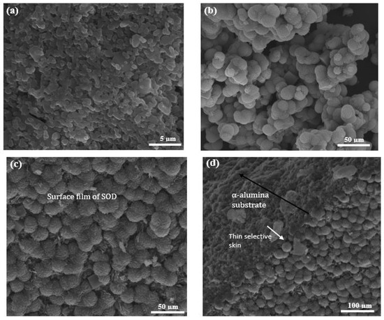
Figure 6.
SEM images of (a) 200 nm layer (Innermost layer) of the α-Al2O3 support; (b) SOD crystals obtained from the bottom of the autoclave during PPH, (c) surface of membrane prepared via the direct hydrothermal synthesis, and (d) cross-section of membrane prepared via the direct hydrothermal synthesis.
Membrane prepared via the direct hydrothermal synthesis technique also shows a continuous growth of SOD crystals on the innermost layer of the support (200 nm layer), though with a few defects (see Figure 6c). It is noteworthy to mention that the 1200 nm layer (outermost layer) of the support was completely wrapped with Teflon tape to prevent penetration of precursor solution into the pores of the support during the direct hydrothermal synthesis. As a comparison, SEM image of the ceramic support (tube side) is shown in Figure 6a. From the micrograph depicted in Figure 6d, a clear interface between the zeolite layer and support could be identified with limited penetration of the zeolitic layer into the underlying pores of the support. These observations confirm that a thin-film membrane was formed, and also agrees with similar studies conducted by Fan et al. [41] and Lafleur et al. [27]. Micrographs of SOD crystals collected from the bottom of the autoclave after the hydrothermal synthesis are depicted in Figure 5a and Figure 6b. The SEM images in Figure 5a and Figure 6a show thread-ball shapes of SOD crystals and this observation agree with literature [15,27,28,39,41].
3.2. Single Gas Permeation
Comparison of results obtained from the single gas permeation experiments provide information about the reproducibility of each technique for the synthesis of the membrane. A summary of the results from the single gas permeation conducted at room temperature (25 °C) and at 0.18 MPa feed pressure is presented in Table 1.

Table 1.
Single gas permeation results of the as-synthesized membranes at 25 °C and 0.18 MPa. PPH: Pore-Plugging Hydrothermal.
H2 permeance of the membranes M1, M4, B1, and B2 were the highest compared to that of N2 and CO2. This was expected as H2 possesses the smallest kinetic diameter of 0.289 nm. Membrane M2 and M3 displayed similar H2 and CO2 permeance. This is abnormal considering the size of the CO2 molecule (0.33 nm) to the pore dimension of SOD (0.29 nm). From the XRD patterns (Figure 4), the presence of large pore zeolitic phases such as Na-A (0.41 nm), LTA (0.3-0.45 nm), Na-X (0.73 nm) type zeolites were formed alongside SOD zeolite. The presence of these zeolites in the membranes could have contributed to the relative high CO2 permeance recorded. Even these zeolites could have been instrumental to the surface roughness or even poor intergrowth observed in the membranes. As mentioned in a previous study [39], the presence of different type of zeolites as impurities inside the pores of the support could result in many intercrystalline defects. As a result, CO2 permeance from the synthesized membranes, M2 and M3, in this study were unexpected. Based on these observations, membranes M2 and M3 were considered in the further investigations as reported in this article. The single permeation results for H2, N2 and CO2 from B1 and B2 (membranes prepared via direct hydrothermal synthesis) were in the order of H2 > N2 > CO2. Since the kinetic diameters of these gases are 0.28 nm for H2, 0.36 nm for N2 and 0.33 nm for CO2, one would expect the order as H2 > CO2 > N2. Thus, the observed order could be attributed to the presence of other zeolites as impurities in the membranes as observed in the membranes prepared via PPH. However, membranes prepared via PPH synthesis (M1, M4) show a reverse trend i.e., permeance reduced as kinetic diameter increased (H2 > CO2 > N2). The observed trend could support the hypothesis that gas permeation through membranes prepared by the PPH technique was controlled by the molecular sieving through zeolite channels rather than surface diffusion through grain boundaries as reported in elsewhere [34,43,44].
3.2.1. Effect of Temperature
To have a better understanding of the performance of the as-synthesized membranes, the temperature dependence of the transport property of the membranes was investigated. The effect of temperature on the permeation of H2, CO2, and N2 at a feed pressure of 0.18 MPa through the membrane: M1, M4, B1, and B2 is presented in Figure 7 (for M1 and M4,) and Figure 8 (for B1 and B2). These figures show that H2 permeance exhibited a strong temperature dependence. Though this behaviour considers the mechanism of the permeation behaviour in the context of the single gas permeation behavior with temperature as reported elsewhere [22,45]. Thus, it is evident that at low temperature and at ambient pressure, H2 was only weakly absorbed on SOD zeolite as seen from Figure 7 and Figure 8. It was observed also that the permeance of H2 through the SOD membrane increased with increasing temperature, indicating that H2 permeation through the membranes could be governed by activated diffusion behavior [46].
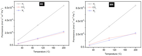
Figure 7.
Effect of permeation temperature on H2, CO2, and N2 permeance of membrane M1 (PPH-1 interruption) and M4 (PPH-2 interruptions).
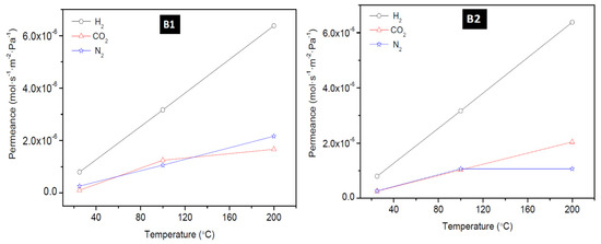
Figure 8.
Effect of permeation temperature on H2, CO2, and N2 permeance of membrane B1 and B2 prepared via the direct hydrothermal method.
Also, H2 permeance does not show a maximum in the range of temperature tested as reported elsewhere. For example, a study by Kanezashi and Lin [47] where H2 and CO2 permeation through MFI membranes synthesized on alumina support via secondary seeded growth method was measured shows that the permeance of H2 and CO2 decreased with increasing temperature. The decrease in permeance was attributed to the Knudsen-type temperature dependency display of the membrane up to 500 °C and this agrees with studies reported elsewhere [48,49,50]. At the same time, these studies [48,49,50] suggested that increase in H2 and CO2 permeance with an increase temperature indicates that permeation is controlled by activated diffusion instead by Knudsen diffusion. On the other hand, constant CO2 permeance at increasing temperature observed by Farjoo and coworker [51] was attributed to the combined contributions from activated process and non-zeolitic flux.
3.2.2. Effect of Feed Pressure
The permeance of H2, CO2, and N2 as a function of feed pressure at 25 °C for membrane M1, M4, B1, and B2 is presented in Figure 9 and Figure 10. The permeance of H2, CO2, and N2 were observed to depend on the feed pressure for the temperature range considered in this study. Maximum H2 permeance obtained for membrane M1 was 6.32 × 10⁻⁶ mol·s−1·m−2·Pa−1 at 200 °C and 0.18 MPa feed pressure and this value reduced to 1.58 × 10⁻⁶ mol·s−1·m−2·Pa−1 when the pressure was increased. Similarly, CO2 permeance and N2 permeance decreased as the pressure was increased. This is expected because permeance is inversely proportional to the change in transmembrane pressure. Since the pressure on the permeate side was kept constant during the experiment, an increase in the feed pressure indicates an increase in the transmembrane pressure, thus a decrease in the permeance. The lowest N2 permeance and CO2 permeance obtained for membrane M1 at room temperature (25 °C) and 0.48 MPa were 6.83 × 10⁻⁸ mol·s−1·m−2·Pa−1 and 6.50 × 10⁻⁸ mol·s−1·m−2·Pa−1, respectively. According to Hosseinzadeh Hejazi et al. [50], a constant permeance or a slight reduction in permeance as a function of pressure should be observed if the zeolitic pores are greater than the kinetic diameter of the permeated molecules and the permeation is only through the zeolitic pores. Gas can permeate through zeolitic pores and non-zeolitic pores in zeolite membranes. When these defects (non-zeolitic pores) are relatively large, they provide non-selective pathways, and viscous flow becomes the predominant mechanism with an increase in pressure. Also, presence of small defects will result in Knudsen mechanism controlling the separation, thus making the membrane semi-selective with flux remaining almost constant as pressure increased [50,51]. Constant flux at increasing feed pressure, while keeping the permeate pressure constant, will result in the decrease of permeance as a function of pressure as observed in this study and could indicate presence of defects in the membranes as well. The effect of temperature on H2 permeation of HSOD zeolite membrane investigated by Vaezi and Babaluo, [10] showed that H2 permeance and CO2 permeance slightly increased as a function of mean pressure and this was attributed to the presence of impurities providing larger pore sizes than the size of the HSOD membranes for the transport of smaller gases.
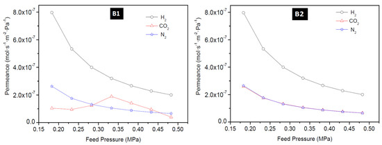
Figure 9.
H2 permeance, CO2 permeance and N2 permeance as a function of feed pressure at 25 °C for membrane M1 prepared using PPH (1-interruption) and M4 using PPH (2-interruptions).
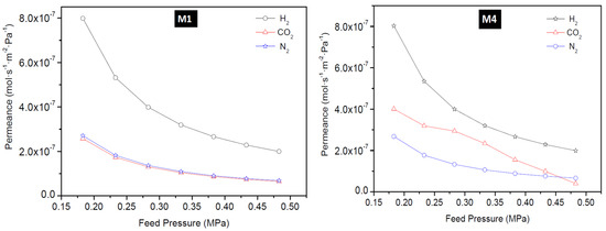
Figure 10.
H2 permeance, CO2 permeance, and N2 permeance as a function of feed pressure at 25 °C for membrane B1 and B2 prepared using the direct hydrothermal method.
3.2.3. Ideal Selectivity
Ideal selectivity during the single gas permeation was obtained for the gases and all the as-synthesized membranes in this study. The ideal selectivity of H2/CO2 as a function of feed pressure for all the membranes is presented in Figure 11. Membrane M1 and B2 displayed a near-constant ideal selectivity of 3.10 for the range of feed pressure investigated at 25 °C. This value is lower than the predicted theoretical H2/CO2 Knudsen selectivity of 4.7, suggesting little contribution of zeolitic pores to the permeation in these two membranes. Even, the selectivity of these membranes did not improve when the temperature was increased to 200 °C. Membrane M2 and M3 displayed the least ideal selectivity value of 1.52 which supported the early conclusion that these membranes were of very poor quality because of the presence of other phase zeolites.
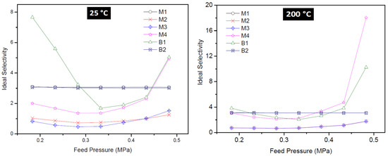
Figure 11.
Ideal selectivity of H2/CO2 as a function of feed pressure of all membranes at 25 °C (left) and 200 °C (right).
At high temperatures, CO2 adsorption on the surface of the zeolite pores of M2 and M3 weakened dramatically and its mobility increased. As a result, membranes M2 and M3 displayed the least H2/CO2 selectivity (ideal). In other words, these membranes did not show molecular sieving ability. Instead the membranes possess large non-selective pores that are larger than the kinetic diameter of H2 and CO2, thereby allowing viscous flow through the pores of these membranes.
Membrane B1 displayed high H2/CO2 selectivity (ideal) of 7.66 at 0.18 MPa and 10.25 at 0.48 MPa, indicating more contribution of the zeolitic pores to the permeation and also that a drastic decrease in the number of non-zeolitic/non-selective pores whose average size is greater than the kinetic diameter of the permeated gases. Membrane prepared via the pore-plugging hydrothermal synthesis using two interruptions steps of one hour each (membrane M4) resulted in membranes displaying the best quality and thus the best-performing membrane. The membrane displayed ideal selectivity for H2/CO2 of 4.94 at 25 °C and 18.03 at 200 °C, at a feed pressure of 0.48 MPa. The high selectivity can be attributed to the much stronger adsorption of CO2 on the membrane surface which limits its diffusion through the membrane. By interrupting the synthesis two times, more precursor would have transported inside the pores of the support leading to complete blocking of the support pores by sodalite crystals after the second interruption. Based on these findings, it can be concluded that the fraction of “non-selective” viscous flux in membrane M4 was very small. Hence, membrane M4 possesses more zeolitic pores that contribute to selective separation with very little non-zeolitic pores. It is noteworthy to mention that a decrease in ideal selectivity with increasing pressure suggests gas transport flow through non-zeolitic regions and macroporous defects (viscous flow contribution) [28,50].
3.3. Mixture Separation Test
Membranes M4 and B1 that displayed the best single gas permeation results (considering the H2/CO2 ideal selectivity) were tested in H2/CO2 (60/40) mixture separation. During the mixture gas separation, H2 permeance obtained was 1.19 × 10⁻⁷ mol·s−1·m−2·Pa−1 for membrane B1 and 1.06 × 10⁻⁷ mol·s−1·m−2·Pa−1 for membrane M4 at 25 °C and 0.18 MPa feed pressure. From Figure 12, the permeance of the weakly adsorbed H2 is more reduced when compared to that of the strongly adsorbing CO2. According to Lindmark and Hedlund [52], this suggests that the effective pore size of the membrane prepared in this study approaches the size of the permeating molecules. The H2 permeance and the CO2 permeance observed at the same temperature, 25 °C, for both single gas permeation experiments and the mixture gas separation experiments show that H2 permeance in the single gas permeation is 6–7 times lower that the value obtained during the mixture gas separation experiments. This observation could be attributed to the competition between the two gases during the mixture gas separation due to adsorbate-adsorbate interaction and/or adsorbate-membrane wall interaction.
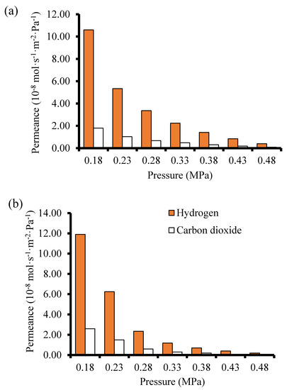
Figure 12.
Gas permeance as a function of pressure during the mixture gas separation at 25 °C (a) membrane M4 prepared using 2-interruption steps PPH synthesis method (b) Membrane B1 prepared by the direct hydrothermal synthesis method.
Table 2 shows the comparison of the H2/CO2 separation performance of the membranes fabricated and tested in this study with literature. Though the results obtained from literature employed different type of membranes, the differences in the separation performance of membranes synthesized in this study compared to that of the membranes from literature could be attributed to the difference in preparation protocols and the membrane supports. Membrane M4 prepared via pore-plugging hydrothermal synthesis technique using two interruption steps displayed a higher separation factor (SF) of 4.24 for H2/CO2 mixture at a high feed pressure of 0.48 MPa and at 25 °C. The SF increased as feed pressure increased from 0.18 MPa to 0.48 MPa. The SF for membranes prepared in this study tested at 25 °C is lower than the SF of 7.2 for the H2/CO2 at 50 °C for ZIF 22 reported by Huang et al. [53]. The pore size of ZIF 22 was about 0.3 nm, therefore it is expected that its separation performance for H2/CO2 will be higher when compared to that of the membranes in this study. It is noteworthy to mention that a binary mixture of H2/CO2 (50:50) was used in ref. [53] instead of 60:40 used in this work was used. Though the partial pressure of the feed used in this work is higher than the one used in ref. [53], but conducting the separation reported in ref. [53] at Wicke–Kallenbach mode where TMP = 0 and with the use of a sweep gas might contribute to the higher performance reported. Furthermore, Yin et al. [54] prepared zeolite NaX composite membrane via the secondary seeded growth method and employed the membrane to separate a 50:50 mixture of H2/CO2. The authors obtain a SF of 4.57. NaX is a zeolite with polar sites and has strong electrostatic interactions with polar gas like CO2 which contributed to H2/CO2 separation. SAPO-34 zeolite membrane prepared on chitosan modified support for H2/CO2 separation was reported by Das et al. [55]. The authors reported that the SF for H2/CO2 increased to 4.2 when the partial pressure of CO2 in the feed was increased. By synthesizing and using a unique membrane having a bilayer membrane structure with an intermediate macroporous yttria stabilized zirconia (YSZ) for H2/CO2 separation, Wang et al. [56] reported a H2/CO2 SF of 25.3 at 450 °C. Huang and co-workers [14] prepared LTA zeolite membranes in the presence of covalent linkers via the direct hydrothermal synthesis method on disk support and reported a SF of 5.5 and CO2 permeance of 6.8 × 10⁻⁸ mol·s−1·m−2·Pa−1 for the membrane when used to separate H2/CO2 mixture.

Table 2.
Comparison of mixture gas separation data of the SOD membrane in this study with other membranes in the literature. W-K: Wicke–Kallenbach technique; DH: Direct hydrothermal; SR: Solvothermal Reaction; PI: Phase Inversion; SG/UI: Seeded Growth/Ultrasonic Irradiation; SSG: Secondary Seeded Growth; PPH: Pore-Plugging Hydrothermal; SSOD/PSF: Silica Sodalite/Polysulfone; SF: Separation Factor.
Considering the different experimental conditions, the different support used, and the different synthesis techniques employed by these authors, the SF for H2/CO2 obtained for SOD membrane (4.13–4.24) in this study is very comparable to values reported in literature, though still lower than the theoretical value of Knudsen diffusion of 4.7. Based on these findings, it is likely that the gases permeated through the grain boundary in the membranes synthesized in this study rather than through the zeolitic pores of the SOD. However, interrupting the hydrothermal synthesis twice had a positive effect as mentioned in Section 3.2.2. By synthesizing zeolite membrane without interruption, zeolite crystals are only grown on the surface of the membranes. On the other hand, interrupting the synthesis only once may have led to inefficient pore-plugging of the support with zeolite crystals.
4. Conclusions
Nanocomposite SOD/α-alumina membranes, prepared via the pore-plugging hydrothermal (PPH) synthesis using one interruption, two-interruption steps, and prepared via direct hydrothermal synthesis have been presented. These membranes were characterized and tested for separation of H2/CO2 mixture, first by single gas permeation tests and then by mixture gas separation. The nanocomposite membrane, M4, synthesized via PPH synthesis using two interruption steps displayed the best ideal selectivity of 8.76 compared to the thin-film membranes during the single gas permeation tests. The H2 permeance of this membrane was 1.59 × 10⁻⁶ mol·s−1·m−2·Pa−1 at 200 °C and 0.48 MPa. The good performance of this membrane could be attributed to the due to enhanced pore plugging effect after the second interruption step. When the membrane was tested at room temperature using a binary gas mixture of H2/CO2 (60:40), the H2 permeance decreased to 1.06 × 10⁻⁷ mol·s−1·m−2·Pa−1 attributable to the adsorbate-adsorbate and adsorbate-membrane wall interactions during the separation. However, the results have demonstrated that by optimizing the synthesis variables during PPH could pave the way for the development of high-quality nanocomposite SOD/α-alumina membranes that could display better separation performance for H2/CO2 separation. Availability of this type of membranes could fast track the development and commercial the Integrated Gasification Combined Cycle (IGCC) technologies employable in the pre-combustion CO2 capture.
Author Contributions
Conceptualization, M.O.D.; methodology, O.E.-I.; validation, M.O.D.; formal analysis, O.E.-I.; investigation, O.E.-I.; resources, S.O.B., M.O.D.; data curation, O.E.-I.; writing—original draft preparation, O.E.-I.; writing—review and editing, O.E.-I., S.O.B., M.O.D.; supervision, M.O.D., S.O.B.; project administration, M.O.D., S.O.B.; funding acquisition, S.O.B. All authors have read and agreed to the published version of the manuscript.
Funding
The research was funded by the Department of Science and Innovation Research Foundation (DSI-NRF) South Africa’s SARChI Clean Coal Technology Grant (Grant Number: 86421).
Acknowledgments
The authors are thankful for training and assistance received from the technical staffs of the Microscopy and Microanalysis Unit (MMU) of the University of the Witwatersrand, Johannesburg, South Africa.
Conflicts of Interest
The authors declare no conflict of interest.
References
- Kita, H.; Horii, K.; Ohtoshi, Y.; Tanaka, K.; Okamoto, K.-I. Synthesis of a Zeolite NaA Membrane for Pervaporation of Water/Organic Liquid Mixtures. J. Mater. Sci. Lett. 1995, 14, 206–208. [Google Scholar] [CrossRef]
- Masuda, T.; Hara, H.; Kouno, M.; Kinoshita, H.; Hashimoto, K. Preparation of an A-Type Zeolite Film on the Surface of an Alumina Ceramic Filter. Microporous Mater. 1995, 3, 565–571. [Google Scholar] [CrossRef]
- Kondo, M.; Komori, M.; Kita, H.; Okamoto, K. Tubular-Type Pervaporation Module with Zeolite NaA Membrane. J. Membr. Sci. 1997, 133, 133–141. [Google Scholar] [CrossRef]
- Duke, M.C.; Zhu, B.; Doherty, C.M.; Hill, M.R.; Hill, A.J.; Carreon, M.A. Structural Effects on SAPO-34 and ZIF-8 Materials Exposed to Seawater Solutions, and Their Potential as Desalination Membranes. Desalination 2016, 377, 128–137. [Google Scholar] [CrossRef]
- Li, H.; Haas-Santo, K.; Schygulla, U.; Dittmeyer, R. Inorganic Microporous Membranes for H2 and CO2 Separation—Review of Experimental and Modeling Progress. Chem. Eng. Sci. 2015, 127, 401–417. [Google Scholar] [CrossRef]
- Dong, J.; Lin, Y.S.; Kanezashi, M.; Tang, Z. Microporous Inorganic Membranes for High Temperature Hydrogen Purification. J. Appl. Phys. 2008, 104, 121301. [Google Scholar] [CrossRef]
- Gallucci, F.; Fernandez, E.; Corengia, P.; van Sint Annaland, M. Recent Advances on Membranes and Membrane Reactors for Hydrogen Production. Chem. Eng. Sci. 2013, 92, 40–66. [Google Scholar] [CrossRef]
- Smart, S.; Beltramini, J.; Diniz da Costa, J.C.; Katikaneni, S.P.; Pham, T. Microporous Silica Membranes: Fundamentals and Applications in Membrane Reactors for Hydrogen Separation. In Handbook of Membrane Reactors; Basile, A., Ed.; Woodhead Publishing Series in Energy; Woodhead Publishing: Sawston, Cambridge, UK, 2013; Volume 1, pp. 337–369. [Google Scholar] [CrossRef]
- Van Niekerk, A.; Zah, J.; Breytenbach, J.C.; Krieg, H.M. Direct Crystallization of a Hydroxy Sodalite Membrane without Seeding Using a Conventional Oven. J. Membr. Sci. 2007, 300, 156–164. [Google Scholar] [CrossRef]
- Vaezi, M.; Babaluo, A.A. Effect of Dehydration Temperature on the H2 Separation Potential of Hydroxy Sodalite Zeolite Membranes. Iran. J. Hydrog. Fuel Cell 2014, 1. [Google Scholar] [CrossRef]
- Fasolin, S.; Romano, M.; Boldrini, S.; Ferrario, A.; Fabrizio, M.; Armelao, L.; Barison, S. Single-Step Process to Produce Alumina Supported Hydroxy-Sodalite Zeolite Membranes. J Mater. Sci. 2019, 54, 2049–2058. [Google Scholar] [CrossRef]
- Guan, L.; Wang, Z.; Lu, D. Evolution of Zeolite Crystals in Self-Supporting Faujasite Blocks: Effects of Hydrothermal Conditions. Materials 2019, 12, 1965. [Google Scholar] [CrossRef] [PubMed]
- Guan, G.; Tanaka, T.; Kusakabe, K.; Sotowa, K.-I.; Morooka, S. Characterization of AlPO4-Type Molecular Sieving Membranes Formed on a Porous α-Alumina Tube. J. Membr. Sci. 2003, 214, 191–198. [Google Scholar] [CrossRef]
- Huang, A.; Bux, H.; Steinbach, F.; Caro, J. Molecular-Sieve Membrane with Hydrogen Permselectivity: ZIF-22 in LTA Topology Prepared with 3-Aminopropyltriethoxysilane as Covalent Linker. Angew. Chem. 2010, 122, 5078–5081. [Google Scholar] [CrossRef]
- Kalantari, N.; Vaezi, M.J.; Yadollahi, M.; Babaluo, A.A.; Bayati, B.; Kazemzadeh, A. Synthesis of Nanostructure Hydroxy Sodalite Composite Membranes via Hydrothermal Method: Support Surface Modification and Synthesis Method Effects. Asia-Pac. J. Chem. Eng. 2015, 10, 45–55. [Google Scholar] [CrossRef]
- Yang, S.; Cao, Z.; Arvanitis, A.; Sun, X.; Xu, Z.; Dong, J. DDR-Type Zeolite Membrane Synthesis, Modification and Gas Permeation Studies. J. Membr. Sci. 2016, 505, 194–204. [Google Scholar] [CrossRef]
- Kazemimoghadam, M.; Rigi, Z.A. Evaluation and Synthesis of Nano-Pore Hydroxysodalite (HS) Zeolite Membranes: Application to Pervaporation of Ethanol/Water Mixture. J. Water Environ. Nanotechnol. 2018, 3, 173–190. [Google Scholar]
- Alshebani, A.; Pera-Titus, M.; Yeung, K.L.; Miachon, S.; Dalmon, J.-A. Influence of Desorption Conditions before Gas Separation Studies in Nanocomposite MFI–Alumina Membranes. J. Membr. Sci. 2008, 314, 143–151. [Google Scholar] [CrossRef]
- Daramola, M.O.; Deng, Z.; Pera-Titus, M.; Giroir-Fendler, A.; Miachon, S.; Burger, A.J.; Lorenzen, L.; Guo, Y. Nanocomposite MFI–Alumina Membranes Prepared via Pore-Pugging Synthesis: Application as Packed-Bed Membrane Reactors for m-Xylene Isomerization over a Pt-HZSM-5 Catalyst. Catal. Today 2010, 156, 261–267. [Google Scholar] [CrossRef]
- Miachon, S.; Ciavarella, P.; van Dyk, L.; Kumakiri, I.; Fiaty, K.; Schuurman, Y.; Dalmon, J.-A. Nanocomposite MFI-Alumina Membranes via Pore-Plugging Synthesis: Specific Transport and Separation Properties. J. Membr. Sci. 2007, 298, 71–79. [Google Scholar] [CrossRef]
- Akhtar, F.; Sjöberg, E.; Korelskiy, D.; Rayson, M.; Hedlund, J.; Bergström, L. Preparation of Graded Silicalite-1 Substrates for All-Zeolite Membranes with Excellent CO2/H2 Separation Performance. J. Membr. Sci. 2015, 493, 206–211. [Google Scholar] [CrossRef]
- Coronas, J.; Santamaría, J. Separations Using Zeolite Membranes. Sep. Purif. Methods 1999, 28, 127–177. [Google Scholar] [CrossRef]
- Li, Y.; Pera-Titus, M.; Xiong, G.; Yang, W.; Landrivon, E.; Miachon, S.; Dalmon, J.-A. Nanocomposite MFI-Alumina Membranes via Pore-Plugging Synthesis: Genesis of the Zeolite Material. J. Membr. Sci. 2008, 325, 973–981. [Google Scholar] [CrossRef]
- Miachon, S.; Landrivon, E.; Aouine, M.; Sun, Y.; Kumakiri, I.; Li, Y.; Prokopová, O.P.; Guilhaume, N.; Giroir-Fendler, A.; Mozzanega, H.; et al. Nanocomposite MFI-Alumina Membranes via Pore-Plugging Synthesis: Preparation and Morphological Characterisation. J. Membr. Sci. 2006, 281, 228–238. [Google Scholar] [CrossRef]
- Alshebani, A.; Pera-Titus, M.; Landrivon, E.; Schiestel, T.; Miachon, S.; Dalmon, J.-A. Nanocomposite MFI–Ceramic Hollow Fibres: Prospects for CO2 Separation. Microporous Mesoporous Mater. 2008, 115, 197–205. [Google Scholar] [CrossRef]
- Daramola, M.O.; Burger, A.J.; Pera-Titus, M.; Giroir-Fendler, A.; Miachon, S.; Lorenzen, L.; Dalmon, J.-A. Nanocomposite MFI–Ceramic Hollow Fibre Membranes via Pore-Plugging Synthesis: Prospects for Xylene Isomer Separation. J. Membr. Sci. 2009, 337, 106–112. [Google Scholar] [CrossRef]
- Lafleur, M.; Bougie, F.; Guilhaume, N.; Larachi, F.; Fongarland, P.; Iliuta, M.C. Development of a Water-Selective Zeolite Composite Membrane by a New Pore-Plugging Technique. Microporous Mesoporous Mater. 2017, 237, 49–59. [Google Scholar] [CrossRef]
- Julbe, A.; Motuzas, J.; Cazevielle, F.; Volle, G.; Guizard, C. Synthesis of Sodalite/αAl2O3 Composite Membranes by Microwave Heating. Sep. Purif. Technol. 2003, 32, 139–149. [Google Scholar] [CrossRef]
- Felsche, J.; Luger, S.; Baerlocher, C. Crystal Structures of the Hydro-Sodalite Na6[AlSiO4]6 8H2O and of the Anhydrous Sodalite Na6[AlSiO4]6. Zeolites 1986, 6, 367–372. [Google Scholar] [CrossRef]
- Khajavi, S.; Jansen, J.C.; Kapteijn, F. Preparation and Performance of H-SOD Membranes: A New Synthesis Procedure and Absolute Water Separation. In Studies in Surface Science and Catalysis; Xu, R., Gao, Z., Chen, J., Yan, W., Eds.; From Zeolites to Porous MOF Materials—The 40th Anniversary of International Zeolite Conference; Elsevier: Amsterdam, The Netherlands, 2007; Volume 170, pp. 1028–1035. [Google Scholar] [CrossRef]
- Khajavi, S.; Kapteijn, F.; Jansen, J.C. Synthesis of Thin Defect-Free Hydroxy Sodalite Membranes: New Candidate for Activated Water Permeation. J. Membr. Sci. 2007, 299, 63–72. [Google Scholar] [CrossRef]
- Treacy, M.M.J.; Higgins, J.B. Collection of Simulated XRD Powder Patterns for Zeolites Fifth, 5th ed.; Elsevier: Amsterdam, The Netherlands, 2007. [Google Scholar]
- Jansen, J.C.; Kapteijn, F.; Strous, S.A. Chemical Reaction and Separation Method. U.S. Patent 7214719B2, 8 May 2007. [Google Scholar]
- Xu, X.; Bao, Y.; Song, C.; Yang, W.; Liu, J.; Lin, L. Synthesis, Characterization and Single Gas Permeation Properties of NaA Zeolite Membrane. J. Membr. Sci. 2005, 249, 51–64. [Google Scholar] [CrossRef]
- Daramola, M.O.; Aransiola, E.F.; Ojumu, T.V. Potential Applications of Zeolite Membranes in Reaction Coupling Separation Processes. Materials 2012, 5, 2101–2136. [Google Scholar] [CrossRef]
- Daramola, M.O.; Oloye, O.; Yaya, A. Nanocomposite Sodalite/Ceramic Membrane for Pre-Combustion CO2 Capture: Synthesis and Morphological Characterization. Int. J. Coal Sci. Technol. 2017, 4, 60–66. [Google Scholar] [CrossRef][Green Version]
- Daramola, M.O.; Dinat, A.; Hasrod, S. Synthesis and Characterization of Nanocomposite Hydroxy-Sodalite/Ceramic Membrane via Pore-Plugging Hydrothermal Synthesis Technique. J. Memb. Separ. Tech. 2015, 4, 1. [Google Scholar] [CrossRef]
- Oloye, O.; Eterigho-Ikelegbe, O.; Daramola, M.O. Synthesis and Evaluation of a Nanocomposite Hydroxy Sodalite/Ceramic (HS/Ceramic) Membrane for Pre-Combustion CO2 Capture: Characterization and Permeation Test during CO2/H2 Separation. Mater. Sci. Energy Technol. 2020, 3, 225–231. [Google Scholar] [CrossRef]
- Eterigho-Ikelegbe, O.; Bada, S.; Daramola, M.O.; Falcon, R. Synthesis of High Purity Hydroxy Sodalite Nanoparticles via Pore-Plugging Hydrothermal Method for Inorganic Membrane Development: Effect of Synthesis Variables on Crystallinity, Crystal Size and Morphology. Mater. Today Proc. 2020. [Google Scholar] [CrossRef]
- Nabavi, M.S.; Mohammadi, T.; Kazemimoghadam, M. Hydrothermal Synthesis of Hydroxy Sodalite Zeolite Membrane: Separation of H2/CH4. Ceram. Int. 2014, 40, 5889–5896. [Google Scholar] [CrossRef]
- Fan, W.; Morozumi, K.; Kimura, R.; Yokoi, T.; Okubo, T. Synthesis of Nanometer-Sized Sodalite without Adding Organic Additives. Langmuir 2008, 24, 6952–6958. [Google Scholar] [CrossRef]
- Naskar, M.K.; Kundu, D.; Chatterjee, M. Effect of Process Parameters on Surfactant-Based Synthesis of Hydroxy Sodalite Particles. Mater. Lett. 2011, 65, 436–438. [Google Scholar] [CrossRef]
- Poshusta, J.C.; Tuan, V.A.; Falconer, J.L.; Noble, R.D. Synthesis and Permeation Properties of SAPO-34 Tubular Membranes. Ind. Eng. Chem. Res. 1998, 37, 3924–3929. [Google Scholar] [CrossRef]
- Xu, X.; Yang, W.; Liu, J.; Lin, L. Synthesis of NaA Zeolite Membranes from Clear Solution. Microporous Mesoporous Mater. 2001, 43, 299–311. [Google Scholar] [CrossRef]
- Algieri, C.; Bernardo, P.; Golemme, G.; Barbieri, G.; Drioli, E. Permeation Properties of a Thin Silicalite-1 (MFI) Membrane. J. Membr. Sci. 2003, 222, 181–190. [Google Scholar] [CrossRef]
- Shafie, A.H.; An, W.; Hosseinzadeh Hejazi, S.A.; Sawada, J.A.; Kuznicki, S.M. Natural Zeolite-Based Cement Composite Membranes for H2/CO2 Separation. Sep. Purif. Technol. 2012, 88, 24–28. [Google Scholar] [CrossRef]
- Kanezashi, M.; Lin, Y.S. Gas Permeation and Diffusion Characteristics of MFI-Type Zeolite Membranes at High Temperatures. Available online: https://pubs.acs.org/doi/full/10.1021/jp804586q (accessed on 22 August 2019).
- Coronas, J.; Falconer, J.L.; Noble, R.D. Characterization and Permeation Properties of ZSM-5 Tubular Membranes. AIChE J. 1997, 43, 1797–1812. [Google Scholar] [CrossRef]
- Martínez Galeano, Y.; Cornaglia, L.; Tarditi, A.M. NaA Zeolite Membranes Synthesized on Top of APTES-Modified Porous Stainless-Steel Substrates. J. Membr. Sci. 2016, 512, 93–103. [Google Scholar] [CrossRef]
- Hosseinzadeh Hejazi, S.A.; Avila, A.M.; Kuznicki, T.M.; Weizhu, A.; Kuznicki, S.M. Characterization of Natural Zeolite Membranes for H2/CO2 Separations by Single Gas Permeation. Ind. Eng. Chem. Res. 2011, 50, 12717–12726. [Google Scholar] [CrossRef]
- Farjoo, A.; Kuznicki, S.M. Separation Using Tubular Stainless Steel Supported Natural Clinoptilolite Membranes. Can. J. Chem. Eng. 2016, 94, 2219–2224. [Google Scholar] [CrossRef]
- Lindmark, J.; Hedlund, J. Carbon Dioxide Removal from Synthesis Gas Using MFI Membranes. J. Membr. Sci. 2010, 360, 284–291. [Google Scholar] [CrossRef]
- Huang, A.; Liang, F.; Steinbach, F.; Caro, J. Preparation and Separation Properties of LTA Membranes by Using 3-Aminopropyltriethoxysilane as Covalent Linker. J. Membr. Sci. 2010, 350, 5–9. [Google Scholar] [CrossRef]
- Yin, X.; Zhu, G.; Wang, Z.; Yue, N.; Qiu, S. Zeolite P/NaX Composite Membrane for Gas Separation. Microporous Mesoporous Mater. 2007, 105, 156–162. [Google Scholar] [CrossRef]
- Das, J.K.; Das, N.; Bandyopadhyay, S. Highly Selective SAPO 34 Membrane on Surface Modified Clay–Alumina Tubular Support for H2/CO2 Separation. Int. J. Hydrogen Energy 2012, 37, 10354–10364. [Google Scholar] [CrossRef]
- Wang, H.; Dong, X.; Lin, Y.S. Highly Stable Bilayer MFI Zeolite Membranes for High Temperature Hydrogen Separation. J. Membr. Sci. 2014, 450, 425–432. [Google Scholar] [CrossRef]
- Chang, H.; Wang, Y.; Xiang, L.; Liu, D.; Wang, C.; Pan, Y. Improved H2/CO2 Separation Performance on Mixed-Linker ZIF-7 Polycrystalline Membranes. Chem. Eng. Sci. 2018, 192, 85–93. [Google Scholar] [CrossRef]
- Jang, E.; Kim, E.; Kim, H.; Lee, T.; Yeom, H.-J.; Kim, Y.-W.; Choi, J. Formation of ZIF-8 Membranes inside Porous Supports for Improving Both Their H2/CO2 Separation Performance and Thermal/Mechanical Stability. J. Membr. Sci. 2017, 540, 430–439. [Google Scholar] [CrossRef]
- Sen, M.; Dana, K.; Das, N. Development of LTA Zeolite Membrane from Clay by Sonication Assisted Method at Room Temperature for H2-CO2 and CO2-CH4 Separation. Ultrason. Sonochem. 2018, 48, 299–310. [Google Scholar] [CrossRef]
- Li, Y.; Liang, F.; Bux, H.; Yang, W.; Caro, J. Zeolitic Imidazolate Framework ZIF-7 Based Molecular Sieve Membrane for Hydrogen Separation. J. Membr. Sci. 2010, 354, 48–54. [Google Scholar] [CrossRef]
- Huang, A.; Liang, F.; Steinbach, F.; Gesing, T.M.; Caro, J. Neutral and Cation-Free LTA-Type Aluminophosphate (AlPO4) Molecular Sieve Membrane with High Hydrogen Permselectivity. J. Am. Chem. Soc. 2010, 132, 2140–2141. [Google Scholar] [CrossRef] [PubMed]
- Eden, C.L.; Daramola, M.O. Evaluation of Silica Sodalite Infused Polysulfone Mixed Matrix Membranes during H2/CO2 Separation. Mater. Today Proc. 2020, in press. [Google Scholar] [CrossRef]
Publisher’s Note: MDPI stays neutral with regard to jurisdictional claims in published maps and institutional affiliations. |
© 2020 by the authors. Licensee MDPI, Basel, Switzerland. This article is an open access article distributed under the terms and conditions of the Creative Commons Attribution (CC BY) license (http://creativecommons.org/licenses/by/4.0/).