1. Introduction
Monocone antennas are attractive for industrial, military, and commercial wireless communication systems because they have an omnidirectional radiation pattern with a wide impedance bandwidth. However, these antennas require a large ground plane in wireless transmission applications [
1]. To overcome the drawback of a large ground size, methods for miniaturizing monocone antennas have been investigated. However, the reduced ground size causes a reduction of the bandwidth. To increase the bandwidth of monocone antennas, approaches such as resistive loading or the utilization of ferrite materials have been used [
2,
3,
4]. Even though resistive loading of the monocone antenna expands the impedance bandwidth in the low-frequency band, this results in a decrease in the antenna efficiency over the entire band. The use of ferrite in the monocone antenna mounting expands the low-frequency band, but its use is costly and limited to the high-frequency band. The impedance bandwidth of monocone antennas has been improved by various methods, such as adding a shorting-pin [
5,
6,
7,
8,
9,
10,
11,
12], employing dual-sleeve structures on the ground plane [
13,
14,
15], loading a dielectric substrate in the feed region [
16], loading high-permittivity materials around the antenna [
17], adding a top-cross plate [
18], and cutting slots on the top-loaded patch [
19]. However, the profiles of these monocone antennas are peaked relatively sharply, resulting in impedance bandwidths that are not sufficiently wide.
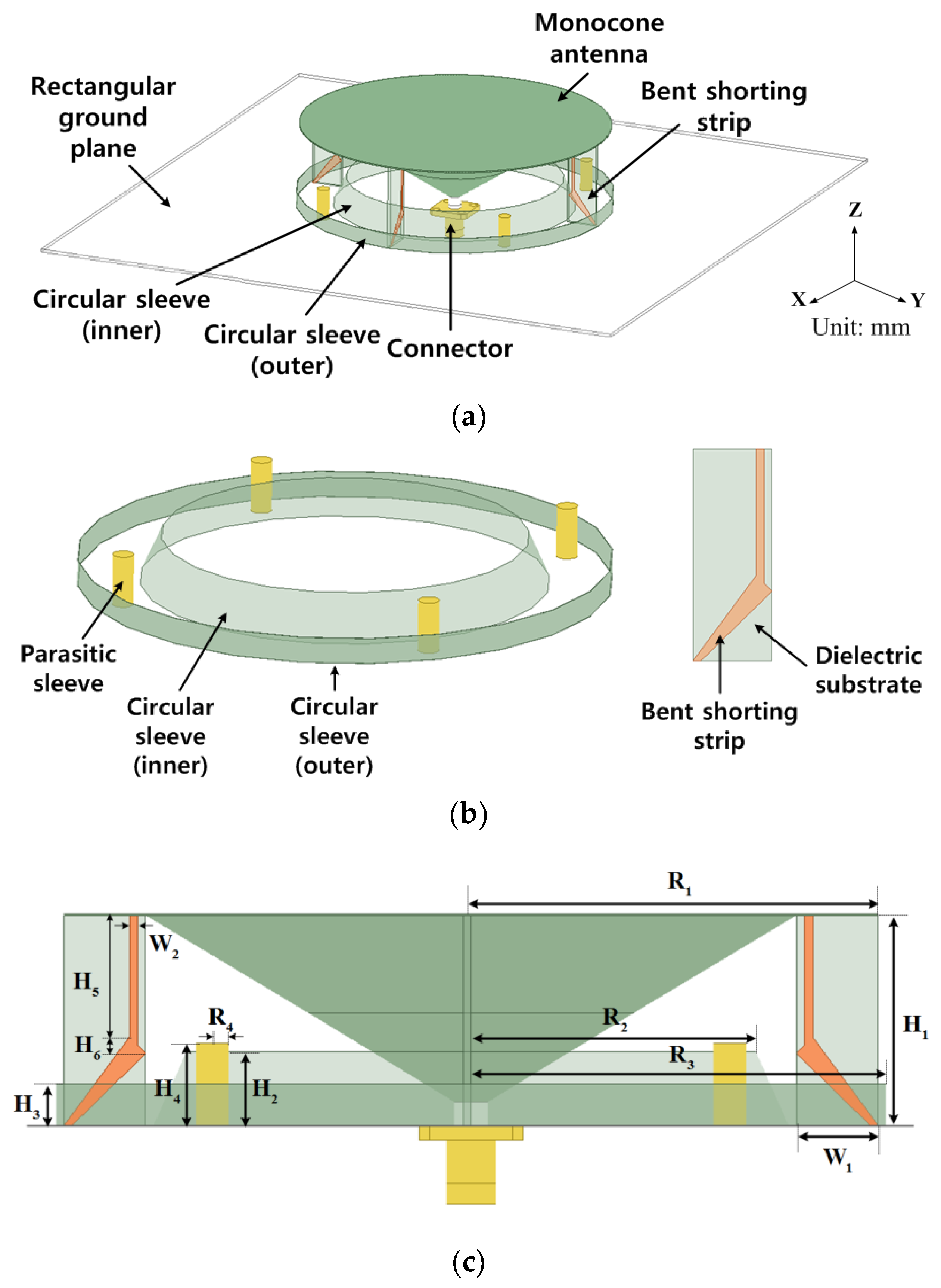
In this paper, a wideband monocone antenna with bent shorting strips, and parasitic and circular sleeves is proposed. The –10 dB reflection coefficient bandwidth ranges from 820 MHz to 5250 MHz. The size reduction of the monocone antenna is achieved by shorting the monocone antenna to the ground plane by four bent shorting strips, with four parasitic and two circular sleeves.
2. Antenna Design
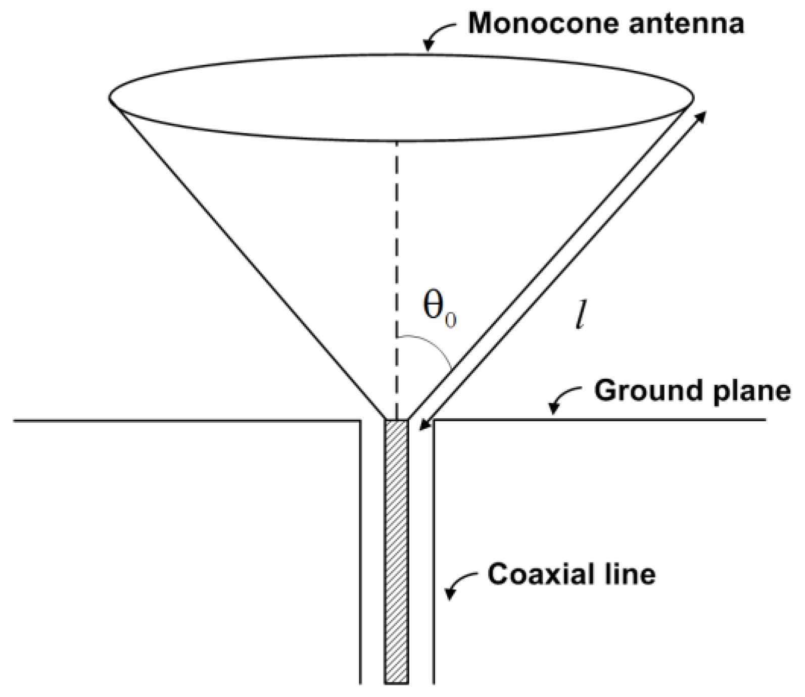
Ideally, an infinite ground plane is required for a monocone antenna to have a monopole-like radiation pattern, but this is usually approximated by a large ground plane in practice. Papas and King presented the input impedance of the monocone antenna using the transmission line theory using the following formula [
20]. The monocone antenna in the infinite ground plane is shown in
Figure 1. The input impedance of a monocone antenna at the feed point for a given half angle (
θ) of a monocone is,
where
and
β/α is the reflection coefficient between the terminating impedance of the cone and free space. is nth order Legendre polynomial, is the spherical Hankel function of the second kind, and is helper funcion. The input impedance of a monocone antenna can be calculated according to the ‘kl’ value where ‘l’ is the slant height of a monocone and k (=) is the wave number. Based on above design equations, the dimensions of a monocone operating at 2.7 GHz are determined by the following: half cone angle () = 56˚ and slant height (l) = 45 mm.
The proposed antenna consists of a monocone antenna, four bent shorting strips, four parasitic sleeves, and inner and outer circular sleeves. By attaching the bent shorting strips from the monocone hat to the ground plane, a reduction in size is achieved. The proposed antenna has a parallel resonance mode that generates the resonance in the low-frequency band. The parallel resonance is generated by an anti-resonance formed by a parallel circuit containing the capacitance between the top monocone hat and the ground plane, and the inductance of the bent shorting strips. Moreover, the parasitic sleeves and circular sleeves are loaded to improve the impedance matching characteristic of the monocone antenna. The monocone antenna and the ground plane are made of a copper with a conductivity of 5.8001 ×
S/m. The radius of the monocone antenna is 0.135
(
is the free-space wavelength at the low frequency) and the antenna height (
) is 0.073
. The height (
) is chosen such that the total antenna structure can be embedded into the fuselage of an aircraft. The design parameters of the proposed antenna are shown in
Figure 2 and the antenna dimensions are given in
Table 1.
3. Antenna Analysis
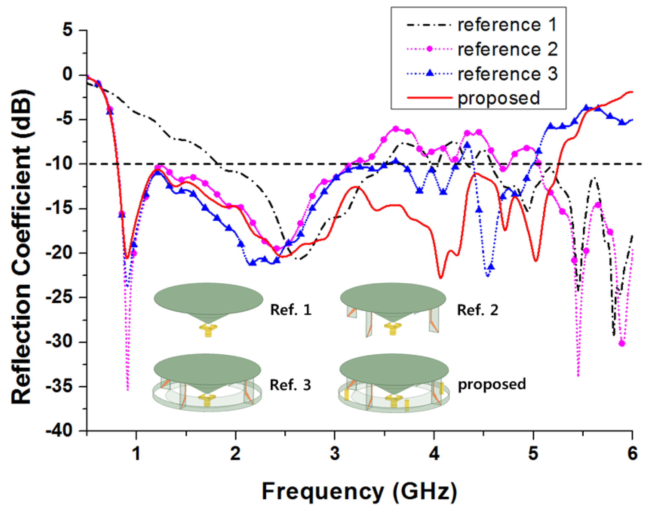
The fractional impedance bandwidth for the proposed antenna is about 146.5%, measured over the –10 dB reflection coefficient range of 810–5250 MHz, as shown in
Figure 3. To analyze the effects of the bent shorting strips, parasitic sleeves, and circular sleeves, a comparison among the reflection coefficients of reference 1 (only monocone), reference 2 (monocone with bent strips), reference 3 (monocone with bent strips and circular sleeves), and the proposed antenna is conducted, as shown in
Figure 3. For reference 1, a –10 dB impedance bandwidth of 1680 MHz (1820–3500 MHz) is obtained. To expand the low frequency limit, the shorting strips are employed such that an additional resonance mode is generated below the fundamental mode [
13,
21]. We adopted the bent shorting strip instead of a straight shorting strip to improve the impedance matching at around 1.2 GHz, as well as to minimize the antenna height. The simulated –10 dB impedance bandwidth of reference 2 is 2340 MHz (810–3150 MHz).
However, the impedance bandwidth of reference 2 is not enough to cover the requirements of the present wireless communication systems. To improve the impedance matching characteristics at the mid-and upper-frequency bands, we employed the inner and outer circular sleeves on the ground plane [
14,
15]. Two –10 dB impedance bandwidth regions of 3500 MHz (810–4310 MHz) and 740 MHz (4440–5180 MHz) are obtained as shown in
Figure 3. It can be seen that the circular sleeves can improve the impedance matching characteristics in the mid- and upper-frequency bands. However, the –10 dB impedance bandwidth of reference 3 is still not satisfied in the frequency ranges between 4310 and 4440 MHz.
To improve the –10 dB impedance matching characteristics at 4310–4440 MHz and further expand the high frequency limit, parasitic sleeves are mounted on the ground plane [
14]. Consequently, the simulated –10 dB impedance bandwidth of the proposed antenna becomes 4440 MHz (810–5250 MHz). This result indicates that the existence of parasitic sleeves effectively improves the impedance matching characteristics in the mid- and upper-frequency bands.
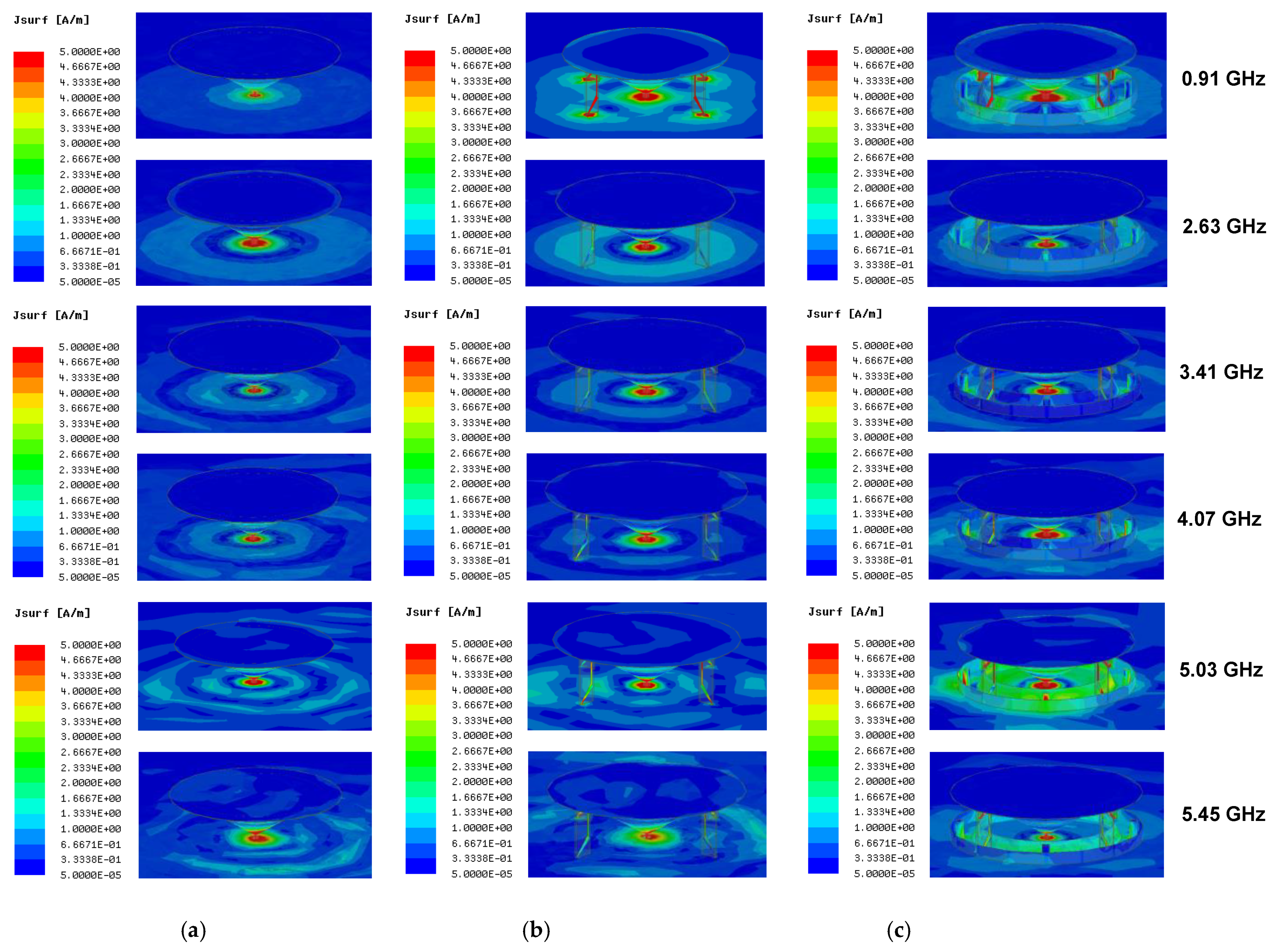
To investigate the operational principle of the antenna, the current distributions of the proposed antenna of reference 1, reference 2, and proposed antenna at 0.91 GHz, 2.63 GHz, 3.41 GHz, 4.07 GHz, 5.03 GHz, and 5.45 GHz are analyzed, as shown in
Figure 4. For reference 1, the currents are mainly concentrated at the center of the ground plane and shows that
resonance mode operates mainly. At 2.63 GHz, strong currents are excited at the center of the ground plane, revealing that the resonance at this frequency is generated by the monocone antenna itself. For reference 2, the currents are strongly excited at the center of the ground plane and along the bent shorting strips from the monocone hat to the ground plane. Particularly, at 0.91 GHz, the current distribution shows that
resonance mode is the principle operating mode. Therefore, the bent shorting strips primarily affect the antenna performance in the low-frequency regime. For the proposed antenna, the currents flowing through the monocone antenna and shorting strips are coupled to the inner, outer, and parasitic sleeves. Particularly, at 3.41 GHz, 4.07 GHz, and 5.03 GHz, the currents are strongly induced on these additional structures (inner, outer, and parasitic sleeves). This phenomenon can be regarded as the main cause of the input impedance matching improvement in the mid- and upper frequency bands.
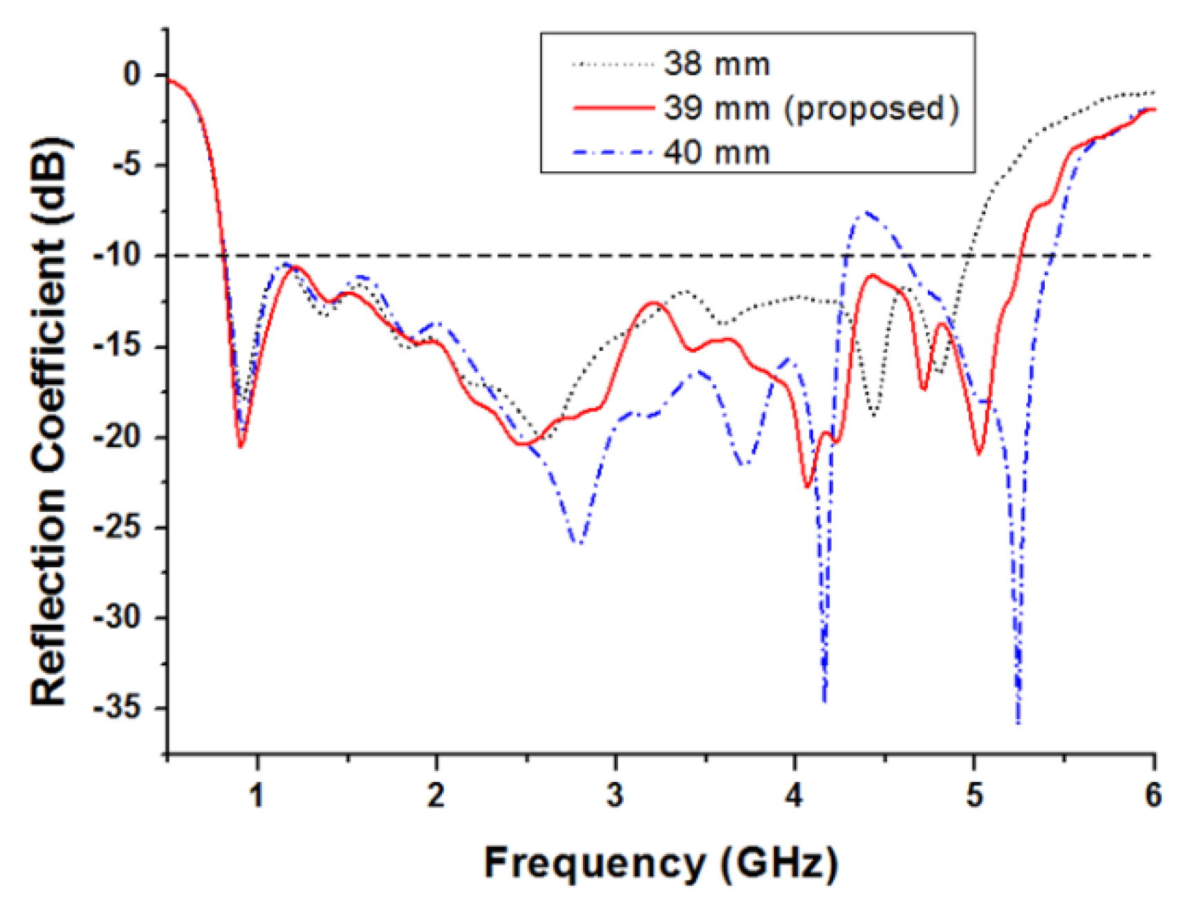
Figure 5 shows the simulated reflection coefficients when the radius of the inner circular sleeve (
) varies from 38 mm to 40 mm.
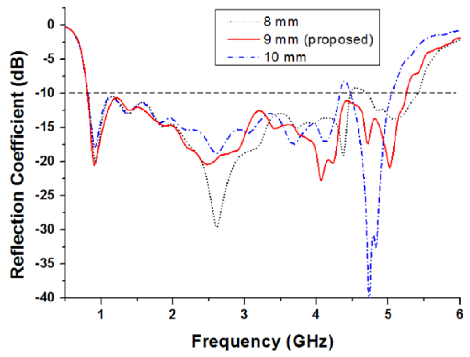
Figure 6 shows the simulated reflection coefficients when the height of the inner circular sleeve (
) varies from 8 mm to 10 mm. It can be seen that the inner sleeve radius and height mainly affect the impedance matching characteristics in the mid- and upper-frequency bands.
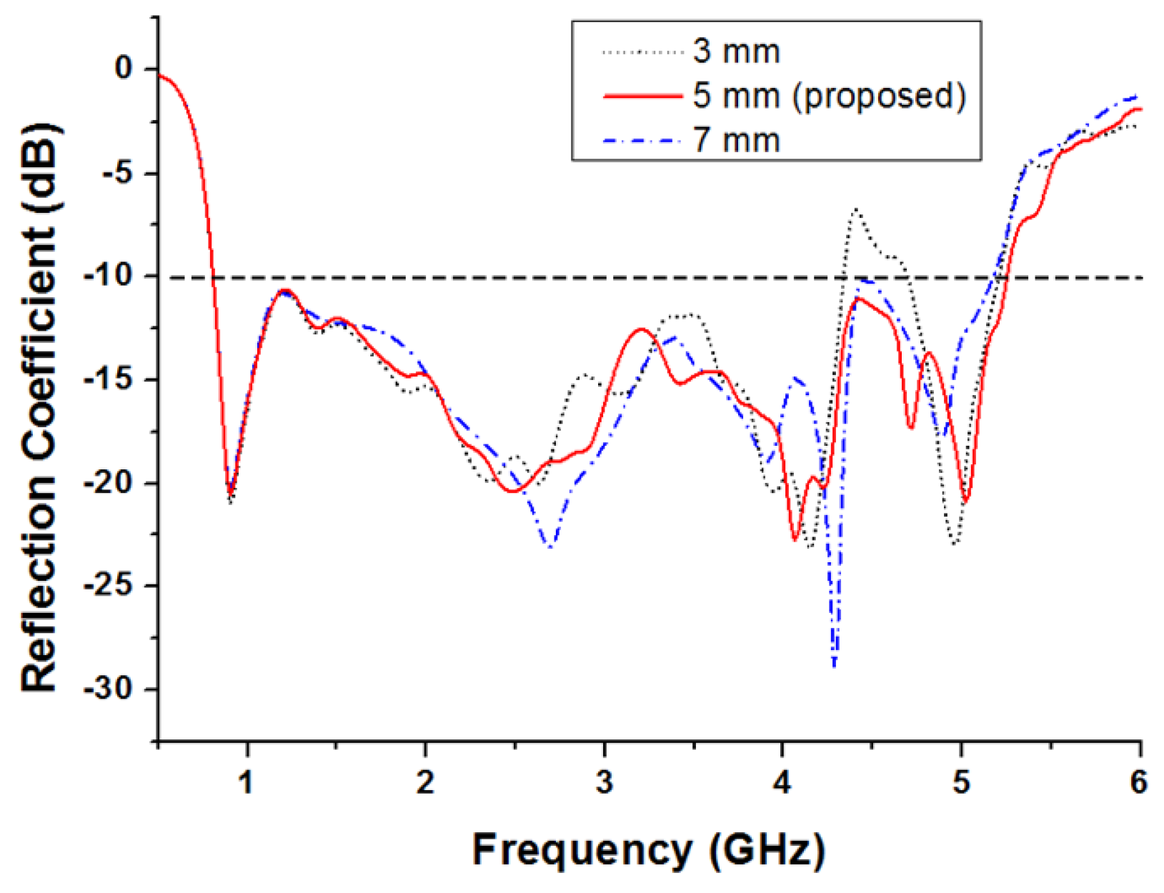
Figure 7 shows the simulated reflection coefficients when the height of the outer circular sleeve (
) varies from 3 mm to 7 mm. It can be seen that the magnitude of the sleeve height mainly affects the impedance matching characteristics in the mid- and upper-frequency bands.
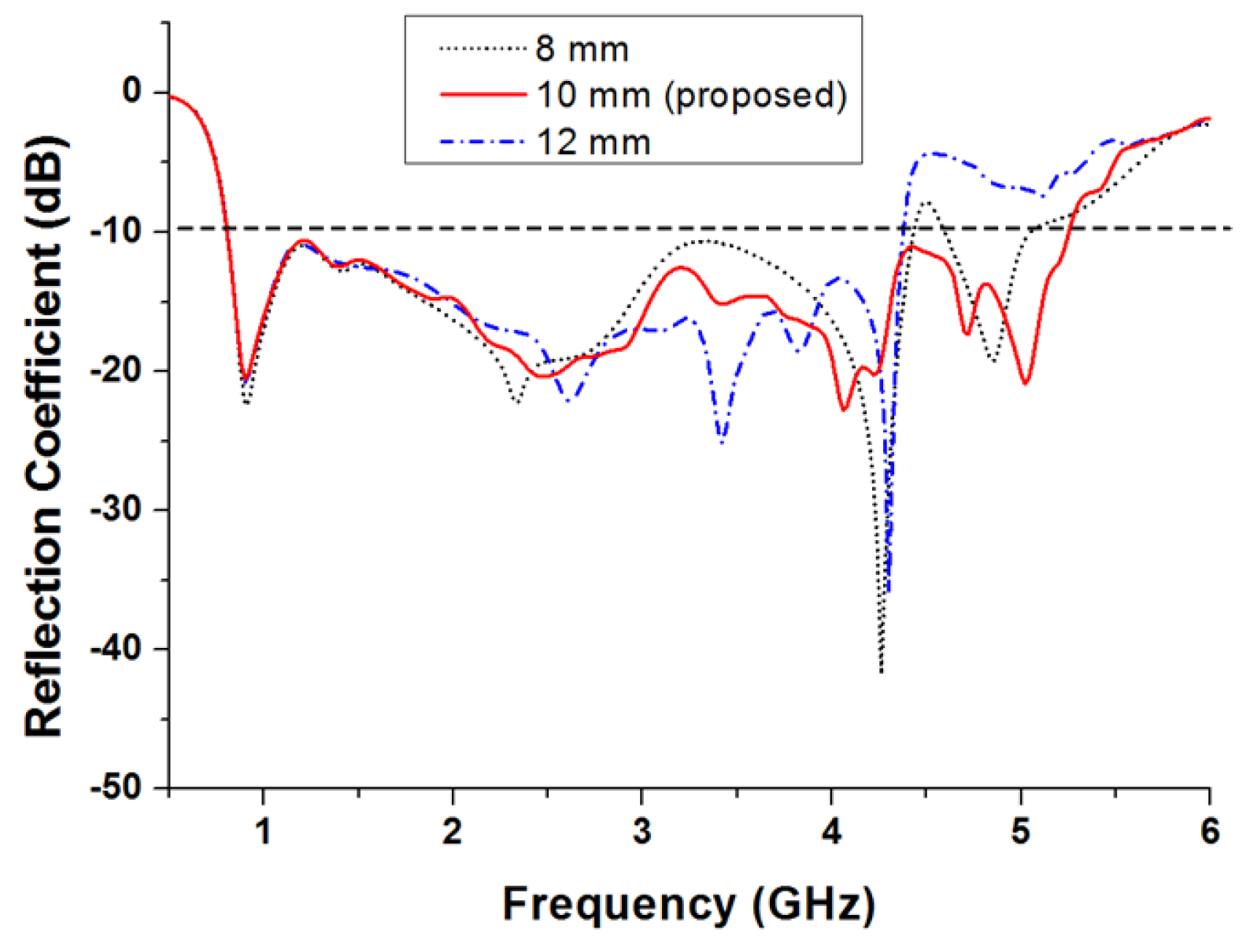
Figure 8 depicts the simulated reflection coefficients when the height of the parasitic sleeve (
) for the proposed antenna varies from 8 mm to 12 mm. The results show that the impedance matching characteristics are mainly affected in the mid and upper bands and that the high-frequency band is expanded by shifting the resonance point of the upper band to the high-frequency side. The improvement of the impedance matching characteristics of the mid and upper bands by the parasitic and circular sleeves is due to capacitance coupling between the sleeves and the monocone antenna.
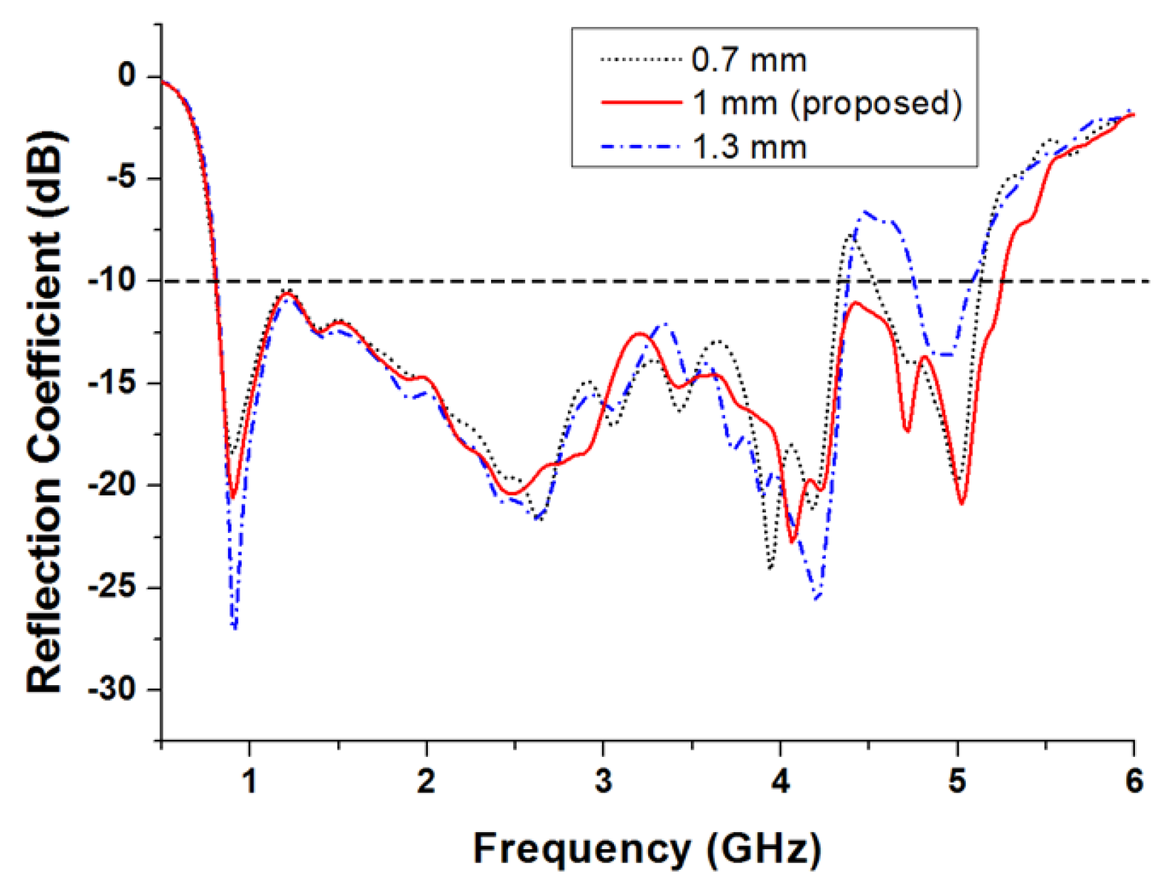
Figure 9 illustrates the effect of the width of the bent shorting strips (
on the impedance matching as it changes from 0.7 mm to 1.3 mm. It is shown that the width of the bent shorting strips affects the impedance matching characteristics in mid- and upper-frequency bands. By properly choosing the width of the bent shorting strips, the bandwidth of the proposed antenna is enhanced by shifting the resonance point of the upper band to the high-frequency side.
4. Experimental Results
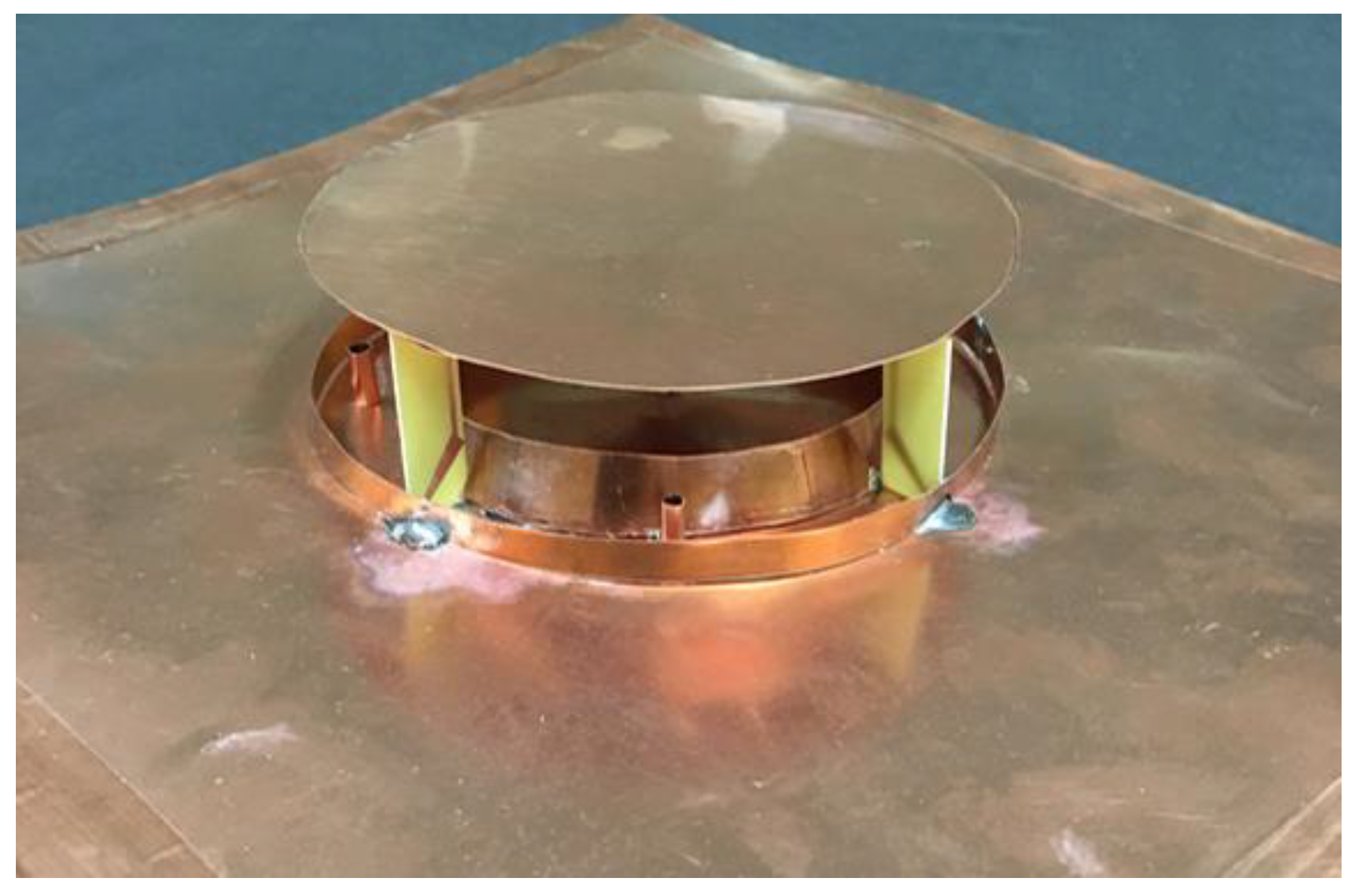
A photograph of the fabricated antenna is shown in
Figure 10.
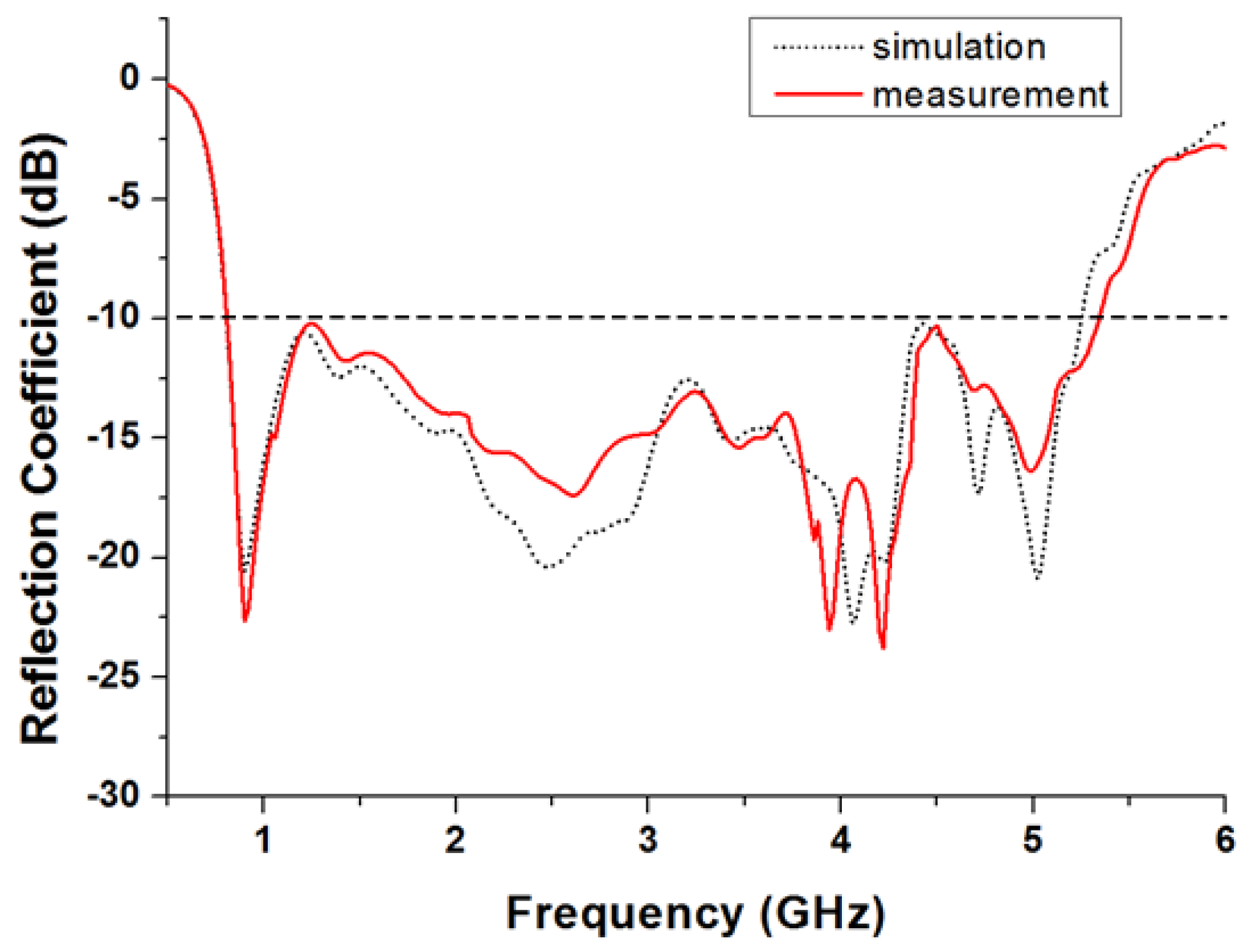
Figure 11 shows the simulated and measured reflection coefficients of the proposed antenna. They agree well over the entire frequency band of interest. The measured –10 dB reflection coefficient bandwidth is 4530 MHz (810–5340 MHz) and the fractional bandwidth is about 147.3%.
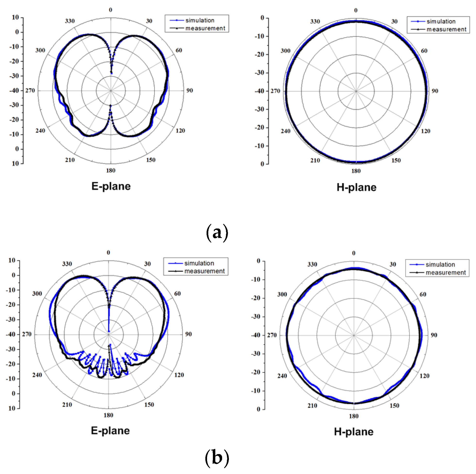
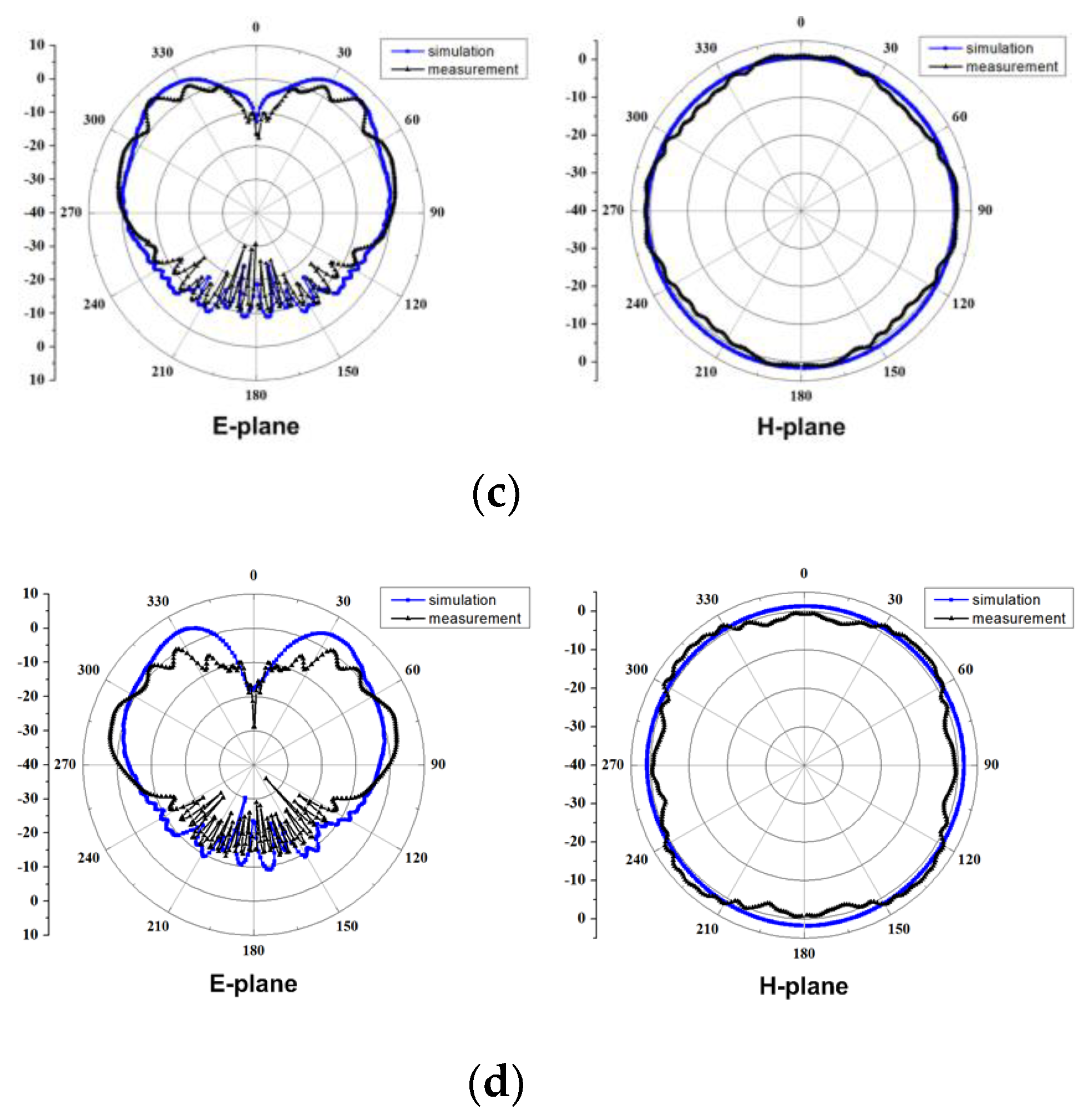
The simulated and measured radiation patterns of the proposed antenna in the E- and H-planes at 0.91 GHz, 2.48 GHz, 4.07 GHz, and 5.03 GHz are shown in
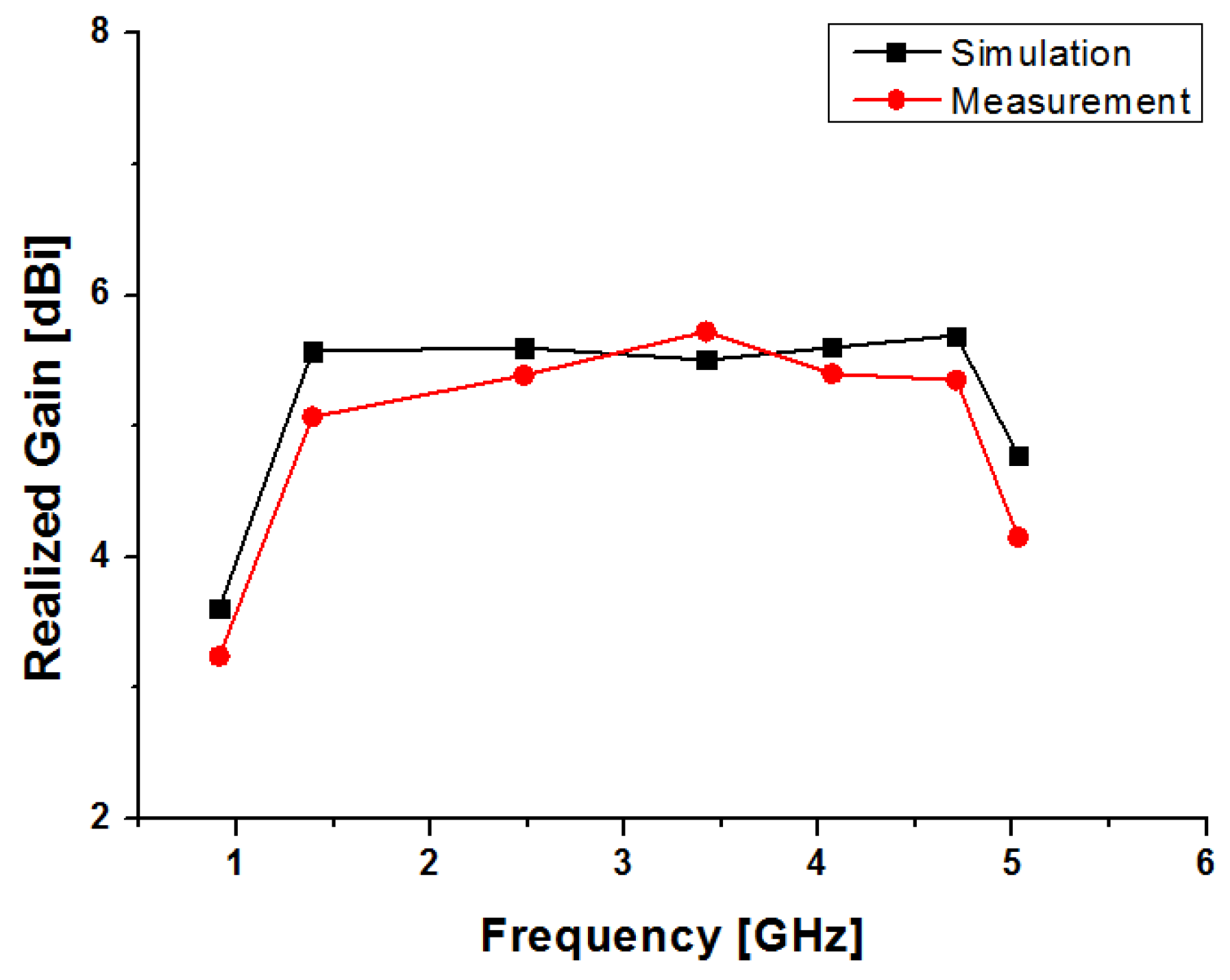
Figure 12 (the xz plane is the E-plane and the xy plane is the H-plane). The measured radiation patterns are in good agreement with the simulated ones. It can be observed that the antenna has dipole-like radiation patterns in the E-plane and omni-directional radiation patterns in the H-plane. Furthermore, the radiation patterns are relatively stable over the entire frequency band. The simulated and measured gains of the proposed antenna are shown in
Figure 13. The simulated maximum gain varies from 3.60 dBi to 5.69 dBi, and measured gain varies from 3.24 dBi to 6.2 dBi within the operating frequency band.
Table 2 provides dimensions, the –10 dB reflection coefficient bandwidth, and fractional bandwidth comparison between the broadband antennas using different methods to improve the bandwidth, along with the proposed antenna. It can be observed that the fractional bandwidth of the proposed antenna is much wider than the others, with a height comparable to the other antennas. The antennas in [
18,
19] have smaller diameters, but their fractional bandwidths are narrower than the proposed antenna. Therefore, the proposed antenna has the advantages of a low profile and wide bandwidth over the other monocone antennas.
5. Conclusions
A low-profile wideband monocone antenna with bent shorting strips, and parasitic and circular sleeves is proposed in this paper. By loading the bent shorting strips, parasitic sleeves, and circular sleeves, miniaturization of the antenna is achieved. By attaching the bent shorting strips from the monocone hat to the ground plane, the proposed antenna has a parallel resonance mode generating the resonance in the low-frequency band. Moreover, the parasitic and circular sleeves improve the impedance matching characteristics of the monocone antenna in the mid-frequency band. From the experimental results, a 147.3% fractional impedance bandwidth for a wide bandwidth –10 dB reflection coefficient is obtained. The proposed antenna provides stable dipole-like radiation patterns for the entire band. Along with the wide impedance bandwidth, the proposed antenna has good radiation properties, which are desirable for wireless transmission and communication systems.


