1. Introduction
The Airy wave packet was first proposed in 1979 [
1]. An Airy beam has the ability to resist diffraction over long distances and can freely accelerate during beam propagation [
2,
3]. In spite of the severity of the imposed perturbations, the Airy beam has a self-healing property and tends to reform [
4]. By using the method of geometrical optics and the Kirchhoff–Huygens integral, as well as the Wigner distribution function, Airy beams have been analyzed to provide a cogent physical explanation of the intriguing features [
5,
6]. The propagation of an Airy beam in free space [
7], in a uniaxial crystal [
8], in a photorefractive medium [
9], in a Kerr medium [
10], in a strongly nonlocal nonlinear media [
11], in water [
12], in turbulence [
13], through an apertured and misaligned paraxial
ABCD optical system [
14], through the system of the fractional Fourier transform [
15], and from a right-handed material to a left-handed material [
16] have been investigated, respectively. The evolution of the Poynting vector and angular momentum of the Airy beam has been investigated in free space [
17]. Based on the method of the stationary phase, the far-field divergent properties of an Airy beam have been examined [
18]. The analytical expression of the beam propagation factor of an Airy beam has been derived on the basis of the Ermakov–Pinney equation [
19]. Under the illumination of a one-dimensional Airy beam, the optical force on a dielectric cylindrical particle of an arbitrary size has been calculated [
20]. Airy beams can be created by employing a transmissive spatial light modulator [
21]. A novel family of finite Airy array beams has been produced by an optical Airy transform system illuminated by Gaussian array beams [
22]. Although Airy beams have been studied more in the optics domain, they have also been investigated in the millimeter wave and radio frequency domains [
23,
24].
Cosh-Airy beams can be considered as a superposition of two Airy beams with different decay factors. Cosh-Airy beams have similar propagation properties to Airy beams, and they possess more manipulation degrees of freedom than the corresponding Airy beams [
25]. The propagation properties of cosh-Airy beams have been investigated in free space [
25] and uniaxial crystals orthogonal to the optical axis [
26], respectively. The periodic phase transition of a cosh-Airy beam has been found in a quadratic-index inhomogeneous medium [
27]. The self-healing ability of the cosh-Airy beam is verified to be higher than that of the corresponding Airy beam [
28]. The above studies on cosh-Airy beams reveal certain characteristics of the beams, but they are not thorough. For example, how can the quality of a cosh-Airy beam be measured? The beam propagation factor, which is defined by the second-order moments, plays an important role in the study of beam propagation characteristics. The international standardization organization committee suggests the beam propagation factor to be a unified standard to evaluate the quality of an arbitrary optical beam. The beam propagation factor can be defined by the ratio of the product of the beam waist and the divergence of the optical beam to the product of the beam waist and the divergence of the fundamental Gaussian beam. The fundamental Gaussian beam is regarded as the comparing standard. In the rest of this article, therefore, the beam propagation factor of a cosh-Airy beam is investigated. The purpose of this paper is to further reveal the propagation properties of a cosh-Airy beam from the second-order moments.
2. Analytical Expression of the Beam Propagation Factor
In the Cartesian coordinate system, the
z-axis is taken to be the propagation axis. The cosh-Airy beam in the source plane
z = 0 takes the form of [
25]
with
E(
x0, 0) and
E(
y0, 0) being given by
where
s =
x0 or
y0,
Ai(⋅) is the Airy function, cosh(.) is the cosh function,
a and
w0 are the decay factor and the transverse scale factor of the Airy part, respectively,
b is the parameter associated with the cosh function, and
w1 is the transverse scale associated with the cosh function. Equation (2) can be written in another form:
where
a± =
a ±
γ and
γ =
bw0/
w1. Therefore, a cosh-Airy beam can be considered as a superposition of two Airy beams with different decay factors. As the beam propagation factor is an invariant, we calculated it in the source plane. The method we used to calculate the beam propagation factor was the second-order moments [
29,
30,
31,
32,
33]. According to the standard definition, the first-order moment of the cosh-Airy beam in the
x-direction is found to be
where
f1(
a+,
x) and
f1(
a−,
x) are given by
<
x0> is just the center of gravity in the
x-direction. The Fourier transforms of
f1(
a±,
x) and
f1∗(
a±,
x) turn out to be [
34]
where the asterisk denotes the complex conjugation. The Fourier transform of
xf1(
a±,
x) yields
Based on the property of the Fourier transform [
34], one can obtain the analytical expressions of
T0(
a+,
a−) and
T1(
a+,
a−). As the analytical expressions of
T0(
a+,
a−) and
T1(
a+,
a−) are lengthy, they are listed in the
Appendix A. The second-order moment of the cosh-Airy beam in the
x-direction of the spatial domain reads as
The analytical expression of
T2(
a+,
a−) is also listed in the
Appendix A. <
x02> is the square of the beam waist in the
x-direction. The second-order moment of the cosh-Airy beam in the spatial-frequency domain is found to be [
29]
where
k = 2
π/
λ, with
λ being the optical wavelength. <
θx2> is the square of the divergence in the
x-direction. We have
with
f2(
a±,
x) being given by
where
Ai′(⋅) is the Airyprime function. The Fourier transform of
f2(
a±,
x) turns out to be
Therefore, the analytical expression of
T3(
a+,
a−) is obtained and listed in the
Appendix A. The cross second-order moment of the cosh-Airy beam in the source plane
z = 0 reads as
The
Mx2 factor of the cosh-Airy beam is given by
Due to the symmetry, the
My2 factor of the cosh-Airy beam reads as
The
M2 factor of the cosh-Airy beam can be readily obtained by virtue of the above results [
35]:
When
γ = 0, the cosh-Airy beam reduces to an Airy beam. In this case, the first-order moment of the Airy beam in the
x-direction is simplified to be
The second-order moment of the Airy beam in the
x-direction of the spatial domain is simplified to be
The second-order moment of the Airy beam in the spatial-frequency domain is simplified to be
Equation (19) is consistent with the results of [
18]. Therefore, the
Mx2 factor of the Airy beam is given by
If the second-order moment of the cosh-Airy beam in the
x-direction of the spatial domain is defined as follows:
then, in this case, the
Mx2 factor of the Airy beam turns out to be
When
ax =
ay =
a, the beam propagation factor of an Airy beam given in [
19] is consistent with Equation (22). The beam propagation factor of an Airy beam is only determined by the decay factor
a, while the beam propagation factor of a cosh-Airy beam is determined by the decay factor
a and the cosh parameter
γ. Therefore, the utility of a cosh-Airy beam over an Airy beam is that it gives another degree of freedom when it comes to controlling properties such as divergence and beam waist.
3. Numerical Calculations and Analyses
As the beam propagation factors in the
x- and
y-directions of the cosh-Airy beam have the same form, only the
Mx2 factor was considered in this study. The
Mx2 factor was determined by the parameters
a+ and
a−, as shown in
Figure 1. When the parameters
a+ and
a− were small, the
Mx2 factor had the larger value. Moreover, the effects of the parameters
a+ and
a− on the
Mx2 factor were the same. With the increase of the parameters
a+, the
Mx2 factor decreased and finally tended to a constant. Since the parameters
a+ and
a− were determined by the decay factor
a and the cosh parameter
γ, the effects of the parameters
a and
γ on the
Mx2 factor were further investigated. By giving the decay factor
a, the
Mx2 factor of the cosh-Airy beam as a function of the cosh parameter
γ is shown in
Figure 2. Since
a± =
a ±
γ must be positive, the cosh parameter
γ should be less than the decay factor
a. When the decay factor
a was greater than 1, the
Mx2 factor first increased and then decreased with the increase of the cosh parameter
γ, and finally, tended to the minimum value. In this case, the
Mx2 factor had a maximum value. As the decay factor
a decreased, the maximum value and the corresponding position of the
Mx2 factor versus the cosh parameter
γ both increased. When the decay factor
a was less than 1, the
Mx2 factor increased with the increase of the cosh parameter
γ. By giving the cosh parameter
γ, the
Mx2 factor of the cosh-Airy beam as a function of the decay factor
a is shown in
Figure 3. As the decay factor
a increased, the
Mx2 factor decreased and finally tended to the minimum value.
In order to analyze the properties of beams more deeply and carefully, the effects of the decay factor
a and the cosh parameter
γ on the squares of the beam waist and the divergence were also studied. By giving the decay factor
a, the square of the beam waist in the
x-direction of the cosh-Airy beam as a function of the cosh parameter
γ is shown in
Figure 4. When the decay factor
a was greater than 1, the square of the beam waist in the
x-direction first increased, then decreased, and finally increased again with the increase of cosh parameter
γ. As the decay factor
a decreased, the first extremum position of the square of the beam waist versus the parameter
γ increased. When the decay factor
a was less than 1, the square of the beam waist in the
x-direction increased with the increase of cosh parameter
γ. By giving the cosh parameter
γ, the square of the beam waist in the
x-direction of the cosh-Airy beam as a function of the decay factor
a is shown in
Figure 5.
When the cosh parameter
γ was relatively large, such as 0.6, the square of the beam waist in the
x-direction first decreased and then increased with the increase of decay factor
a. In this case, the square of the beam waist in the
x-direction had a minimum value. Moreover, the position where the minimum value appeared increased with the increase of the cosh parameter
γ. When the cosh parameter
γ was relatively small, such as 0.1, the square of the beam waist in the
x-direction decreased and finally tended to the minimum value with the increase of decay factor
a. By giving the decay factor
a, the square of the divergence in the
x-direction of the cosh-Airy beam as a function of the cosh parameter
γ is shown in
Figure 6. When the decay factor
a was greater than 1, the square of the divergence in the
x-direction decreased with the increase of the cosh parameter
γ. However, there was a concavity in the curve of the square of the divergence versus the cosh parameter
γ. The concavity was more obvious for the small decay factor
a. When the decay factor
a was less than 1, the square of the divergence in the
x-direction increased with the increase of the cosh parameter
γ.
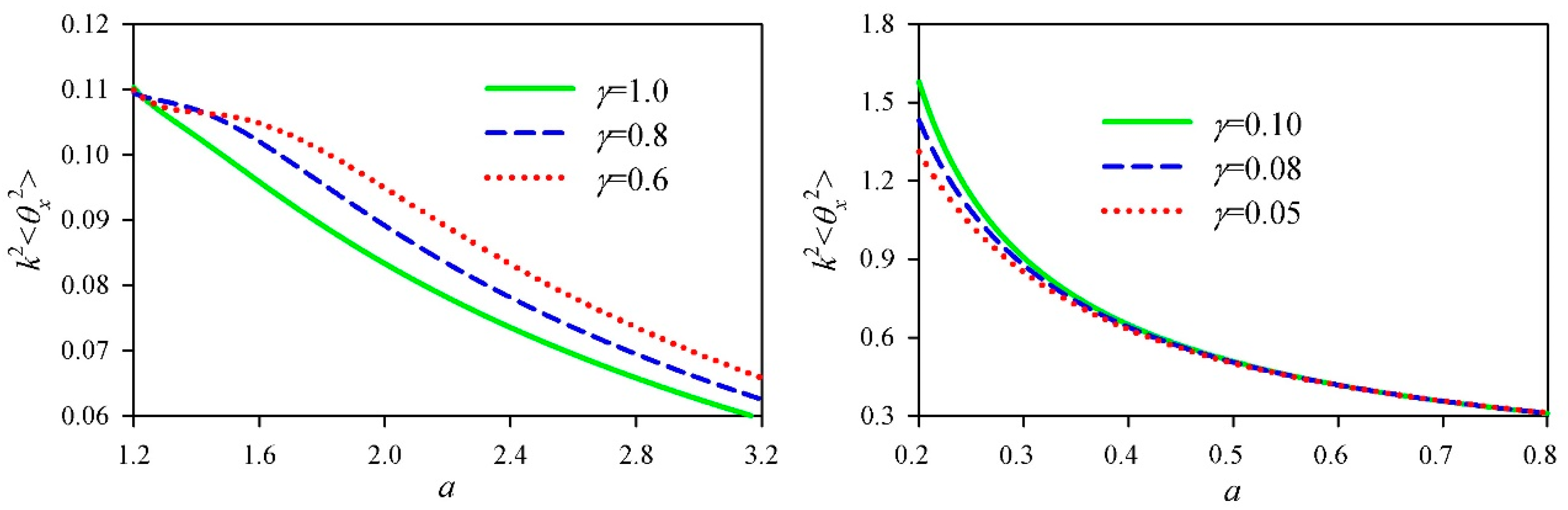
Figure 7 shows the square of the divergence in the
x-direction of the cosh-Airy beam as a function of the decay factor
a with the determined cosh parameter
γ. As the decay factor
a increased, the square of the divergence in the
x-direction decreased.
A cosh-Airy beam can be obtained by a superposition of two Airy beams. The decay factors of these two Airy beams are
a +
γ and
a −
γ, respectively. According to Equation (20), the
Mx2 factor of the Airy beam is small for a large decay factor. The premise of the cosh-Airy beam with a small
Mx2 factor is that these two Airy beams both have small
Mx2 factors. The outcome is that
a +
γ and
a −
γ should both be large enough. In other words,
a should deviate from
γ. From this perspective, it might be easier to understand the physical meaning of the effects of the parameters
a and
γ on the
Mx2 factor. To further understand the beam propagation factor, the normalized intensity distribution in the
x-direction of the cosh-Airy beam is shown in
Figure 8.
w0 = 0.8 μm,
γ = 0.2, and
λ = 0.628 μm in
Figure 8.
z0 =
kw02 represents the Rayleigh length of the Airy part. When
a = 0.4, 0.5, and 0.6, the
Mx2 factor was 2.0376, 1.3379, and 1.1703, respectively. In the source plane, the main lobe of the cosh-Airy beams with different decay factors was nearly the same. Only the position of the main lobe was different. However, side lobes in the source plane were more apparent with the decrease of the decay factor. In the observation plane
z = 5
z0, the side lobes disappeared. Moreover, the cosh-Airy beam expanded with the decrease of the decay factor. With the decrease of the decay factor, therefore, the
Mx2 factor increased.
Figure 8 can be interpreted by
Figure 2,
Figure 4 and
Figure 6. Through this example, one can use the beam propagation factor of the cosh-Airy beam to evaluate its propagation behavior.
4. Conclusions
Based on the second-order moments, the analytical expression of the beam propagation factor of a cosh-Airy beam has been derived. The beam propagation factor was determined by the decay factor
a and the cosh parameter
γ. Since the beam propagation factors in the
x- and
y-directions of the cosh-Airy beam have the same form, only the
Mx2 factor was selected here for numerical calculation. The effects of the decay factor and the cosh parameter on the
Mx2 factor were investigated. When the decay factor was greater than 1, the
Mx2 factor first increased, then decreased, and finally tended to the minimum value with the increase of the cosh parameter. When the decay factor was less than 1, the
Mx2 factor always increased with the increase of the cosh parameter. As the decay factor increased, the
Mx2 factor decreased and finally tended to the minimum value. The effects of the decay factor and the cosh parameter on the squares of the beam waist and the divergence were further investigated. When the decay factor was greater than 1, the square of the beam waist first increased, then decreased, and finally increased again with the increase of the cosh parameter. However, the square of the divergence always decreased with the increase of the cosh parameter. When the decay factor was less than 1, the squares of the beam waist and the divergence increased with the increase of the cosh parameter. When the cosh parameter was relatively large, the square of the beam waist first decreased and then increased with the increase of the decay factor. When the cosh parameter was relatively small, the square of the beam waist decreased with the increase of the decay factor and finally tended to the minimum value. As the decay factor increased, the square of the divergence decreased. The research results can be roughly summarized as follows. The greater the decay factor is than the cosh parameter, the smaller the beam propagation factor of the cosh-Airy beam is. The results obtained here are useful for the further understanding and application of cosh-Airy beams. When one wants to obtain a cosh-Airy beam by means of the superposition of different Airy beams, the present results provide a basis by which one can select the beam parameters to control the beam quality of the expected cosh-Airy beam. Let us use a numerical example to illustrate this problem. For example, the first Airy beam in the source plane is characterized by
. How does one choose the second Airy beam? According to
Figure 2, one can choose the second Airy beam that has the form of
. The superposition of these two Airy beams results in a cosh-Airy beam with
a = (3 + 1)/2 = 2 and
γ = (3 − 1)/2 = 1. The beam propagation factor of the obtained cosh-Airy beam is close to 1.

