Article

New Trajectory Tracking Approach for a Quadcopter Using Genetic Algorithm and Reference Model Methods

1
LSET, Department of Applied Physics, Faculty of Science and Technology Gueliz, Cadi Ayyad University, Marrakech 40000, Morocco
2
Mathematics and Systems Department, Ecole Royale de l’Air, Marrakech 40000, Morocco
*
Author to whom correspondence should be addressed.
Appl. Sci. 2019, 9(9), 1780; https://doi.org/10.3390/app9091780
Submission received: 6 March 2019 / Revised: 2 April 2019 / Accepted: 15 April 2019 / Published: 29 April 2019
(This article belongs to the Special Issue Autonomous Micro Aerial Vehicles: Methods and Applications)

Abstract

:
This paper deals with the trajectory tracking problem for a quadrotor unmanned aerial vehicle (UAV). For this purpose, two control strategies are proposed. First, a flight controller with a hierarchical structure is designed, whereby the complete closed-loop system is divided into two blocks. The system has an inner block for attitude control and an outer block for position stabilization, for a total of six proportional-derivative/proportional-integral-derivative (PD/PID) controllers. The second new trajectory tracking strategy is based on attitude stabilization. In addition to a direct stabilization of yaw and altitude, the x and y positions are stabilized by choosing an appropriate control of roll and pitch angles. The relations between positions (x, y) and rotations (roll, pitch) are derived from the natural flight of the quadcopter. In this second approach, with only four controllers, the quadrotor UAV is able to follow any trajectory. In both approaches, the PD/PID controllers are synthesized using the genetic algorithm method, and compared with those obtained by the reference model method. Furthermore, a comparison between PD and PID controller performance is performed. Thereafter, the robustness of the proposed controllers is tested for trajectory tracking in a disturbed environment. Simulation results demonstrate that for the two approaches, PD controllers show a better behavior with respect to quadcopter stabilization than in trajectory tracking under different conditions.

1. Introduction

In recent years, the control scheme design of vertical take-off and landing (VTOL) unmanned aerial vehicles (UAVs) has become a significant research topic. As exemplified by quadrotors, this is partly due to the growing interest in the development of the technology for these robots. Quadcopters are most well known for being small aircrafts with multiple rotors, with under-actuated, nonlinear, and coupled systems. However, these characteristics lead to great control challenges. By controlling the velocity, and consequently, the thrust of each rotor, a translational motion in three directions (x, y, and z) and a rotation around three axes (roll, pitch, and yaw) are generated. The under-actuated property of quadcopters leads to strong coupling between translational and rotary motions. Therefore, it is an arduous task to control the position or the trajectory tracking of the quadcopter. To deal with this dilemma, the hierarchical control strategy has demonstrated positive performances and it has been widely used to solve trajectory-tracking problems. Since the introduction of quadcopters to the robotic community, numerous projects have been devoted to model and control these platforms, as simple as projects based on linear methods and as complex as nonlinear techniques. In the relevant literature, a great number of controllers have been proposed. Among them, a hierarchy controller for the quadcopter has been developed in [1]. This study uses, a compensated proportional-derivative (PD) control, contributing stable attitude control and accurate position tracking. In [2], a second-order sliding mode controller is developed for the translational dynamic to deal with external negative signal while avoiding the undesired chattering effect. Another nonlinear adaptive hierarchical sliding mode control approach for quadrotors has been developed in [3]. To accomplish trajectory-tracking missions, two controllers have been investigated to solve the problem of the under-actuated nature of the system. Furthermore, a global stability analysis and control design based on the cascade theory has been studied in [4]. The complete closed-loop system was divided into two reduced-order subsystems to deal with the coupling property. The backstepping approach and sliding mode control method has been used in [4] as well. In [5], authors addressed the problem of designing and experimentally validating a controller for steering a quadcopter along a trajectory, while rejecting constant force disturbances. The proposed controller was investigated using the nonlinear adaptive state feedback technique. Other approaches have been widely used in trajectory tracking control, such as the backstepping technique and the adaptive control algorithm. For instance, a flight controller with a disturbance observer was designed using the backstepping technique, which can be seen in [6]. In [7], a nonlinear adaptive algorithm was used for a trajectory tracking control problem for a quadcopter with parametric uncertainty. Combined with the neural network algorithm, the adaptive control algorithm was applied to elaborate a controller for the trajectory tracking for a quadcopter in [8]. In addition, in [9], the adaptive algorithm was used in addition to an adaptive sliding mode observer for fault diagnosis in the quadcopter’s actuator. All of the aforementioned control approaches have proven to be successful in simulation. Some approaches have proven to be successful in experimental environments too, but only under specific operating conditions. Hence, the dynamic properties of the quadcopter are often neglected, which implies that the overall quadcopter dynamics are not represented for effective control. The use of intelligent approaches could be a solution to this conflict. For example, in [10], the fuzzy logic control technique was employed to implement a fuzzy hitting control law, in order to reduce the chattering phenomena on a conventional backstepping sliding mode controller. Likewise, in [11], a fuzzy logic algorithm was used to determine the optimal controller coefficients of a high order sliding mode controller for a quadcopter trajectory tracking control in the presence of uncertainties. More recently, a robust full tracking control design of disturbed quadrotor UAVs with unknown dynamics based on type-2-adaptive fuzzy systems are presented in [12]. Particularly, fuzzy logic has been used in a landing path selection problem for an aircraft carrier in [13]; the fuzzy path selection strategy was proposed, considering the fuzziness of environmental information and human judgment, with the goal of providing the pilot with a more reasonable set of choices. Thus, a neural network algorithm has been widely used in the synthesis of controllers for quadcopter stabilization. A decentralized proportional-integral-derivative (PID) neural network control scheme is proposed in [14] to stabilize a quadrotor helicopter subjected to wind disturbance. The hierarchical structure was adopted in this study, where the inner-loop was designed using a neural network, while a conventional PID is used for the outer loop. Furthermore, in [15], the neural network method is combined with fuzzy logic to optimize the performance of a quadcopter. Owing to its maneuverability and its simplicity, the PID controller has been adopted in most of the literature for controlling a quadcopter. There exist various and widely used classical methods for adjusting a PID. However, these conventional approaches require a linear model of the controlled system for tuning the parameters. To overcome the limitations and drawbacks of linear approaches, a variety of nonlinear algorithms have been developed and applied to improve PID tuning, including optimization techniques. As an illustration, robust PID controllers tuned by particle swarm optimization for a hose transportation system performed by aerial robots was developed in [16]. In addition, in [17], an improved particle swarm optimization approach for identification and control of stable and unstable systems has been studied. Furthermore, a combination of the particle swarm optimization-based algorithm and the evolutionary programming algorithm was introduced in [18]. Moreover, in [19], a trajectory tracking control law optimization using a modified genetic algorithm (GA) for an autonomous aircraft vehicle was proposed. Additionally, genetic algorithm techniques were used in [20] to optimize PID controllers for a quadcopter attitude stabilization.
On the basis of this literature, but differing in many ways, our work deals with the problem of trajectory tracking for quadcopters using two different approaches. In a hierarchical approach, the structure scheme is composed of an internal and external loop. The inner loop is synthesized to control the quadcopter attitude, while the outer loop is designed to stabilize the position motions. The two PD/PID controller blocks are optimized using GA and reference model (RM) techniques. The new second control strategy developed herein is based only on altitude and attitude control. The control of the other two positions (x, y) results from their relationship with the pitch and roll movements of the quadcopter. Again, in the design of the different PDs/PIDs, the two methods (GA and RM) are compared. Thereafter, the performance of the two proposed methods are investigated not only taking into account the system nonlinearities but also the presence of wind disturbances. This paper is arranged as follows: in Section 2, the dynamic model of the quadcopter and the coupling expression between the translational motion equations and the rotational movements are presented. In Section 3, the proposed hierarchical controllers are described, starting with a controller synthesized using the RM approach, then using the GA optimization process. In Section 4, the new strategy of trajectory tracking via attitude stabilization is presented. Likewise, in the first controller, the PD/PID gains are synthesized by utilizing the RM and GA optimization. The simulations were performed using the Matlab-Simulink environment to demonstrate the effectiveness and robustness of all the proposed controllers. Our results are presented and discussed in Section 5, and finally, a conclusion of this work is presented the Section 6.

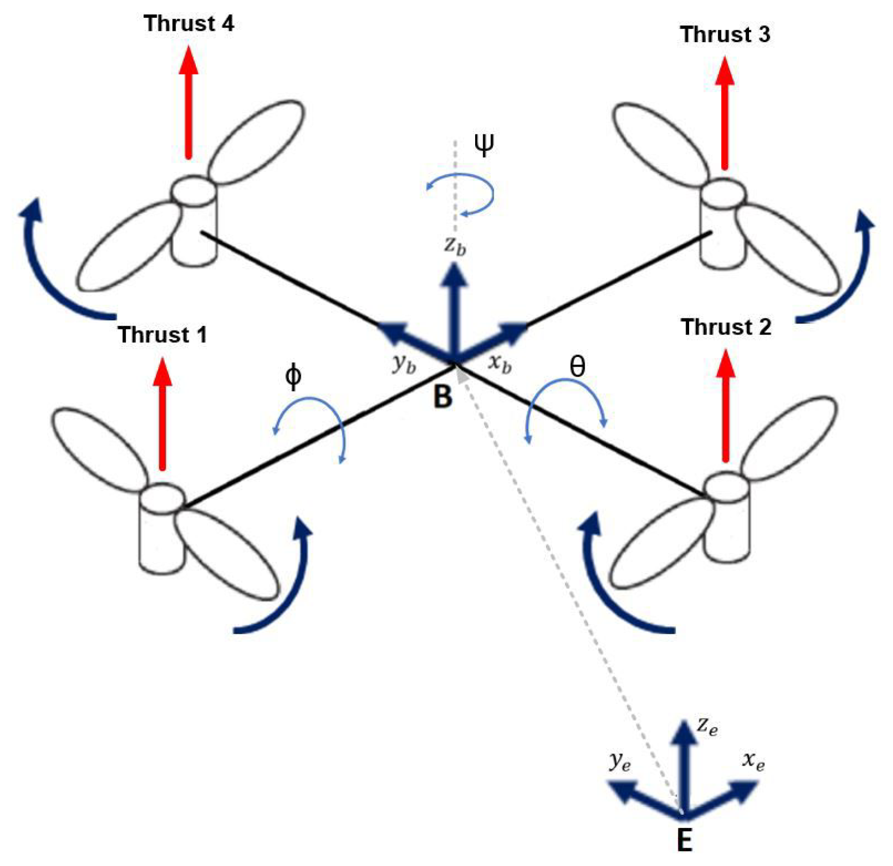
2. Quadcopter Mathematical Model

The quadcopter is composed of four rotors that lift the vehicle and adjust its attitude by the thrust force generation along the body z-axis. The thrust force of each rotor changes along with the input control signals. The rear-front motors ( r 2 and r 4 ) rotate clockwise, while left-right motors ( r 1 and r 3 ) spin in a counterclockwise direction (Figure 1) [21,22]. Vertical motions are produced when the total thrust increases or decreases. By varying front-rear (left-right) rotors, thrust y- translation (x-translation) is achieved.
The quadrotor can be represented as a rigid body in two reference frames; the inertial frame (E) whose origin is located at a fixed point on the earth, and the body frame (B) whose origin is in accordance with the quadrotor center of gravity (Figure 1). The quadcopter mathematical model is derived by making the following assumptions [23]:
  • The quadcopter structure is rigid and symmetrical;
  • The center of gravity lies at the origin of the body reference frame;
  • Wind, ground effect disturbances, and the gyroscopic effect are neglected;
  • The thrust and drag are proportional to the square of the speed of the rotor.
Using Newton–Euler formalism [23,24,25], the full-obtained dynamic model is given as follow (1)–(6):
ϕ ¨ = ( θ ˙ sin ϕ + ψ ˙ cos ϕ cos θ ) ( θ ˙ cos ϕ + ψ ˙ sin ϕ cos θ ) I y I z I x + l U 2 I x ( θ ˙ cos ϕ + ψ ˙ sin ϕ cos θ ) J r ( ω 1 ω 2 + ω 3 ω 4 ) I x ( ϕ ˙ 2 2 ϕ ˙ ψ ˙ sin θ 2 ) K f a x I x
θ ¨ = ( ψ ˙ cos ϕ cos θ θ ˙ sin ϕ ) ( ϕ ˙ ψ ˙ sin θ ) I z I x I y + l U 3 I y ( ψ ˙ sin θ ϕ ˙ ) J r ( ω 1 ω 2 + ω 3 ω 4 ) I y ( θ ˙ 2 cos ϕ 2 + 2 ϕ ˙ ψ ˙ sin ϕ cos ϕ cos θ + ψ ˙ 2 sin ϕ 2 cos θ 2 ) K f a y I y
ψ ¨ = ( ψ ˙ sin ϕ cos θ + θ ˙ cos ϕ ) ( ϕ ˙ ψ ˙ sin θ ) I x I y I z + U 4 I z ( ψ ˙ sin θ ϕ ˙ ) J r ( ω 1 ω 2 + ω 3 ω 4 ) I z ( θ ˙ 2 sin ϕ 2 2 ϕ ˙ ψ ˙ sin ϕ cos ϕ cos θ + ψ ˙ 2 cos ϕ 2 cos θ 2 ) K f a z I z
x ¨ = U x m U 1 K f t x m x ˙
y ¨ = U y m U 1 K f t y m y ˙
z ¨ = g + cos ϕ cos ψ m U 1 K f t z m z ˙
With:
U x = cos ϕ sin θ cos ψ + sin ϕ sin ψ U y = cos ϕ sin θ sin ψ sin ϕ cos ψ .
The control inputs U 1 , U 2 , U 3 , and U 4 are given by (8).
U 1 = b ( ω 1 2 + ω 2 2 + ω 3 2 + ω 4 2 ) U 2 = b ( ω 4 2 ω 2 2 ) U 3 = b ( ω 3 2 ω 1 2 ) U 4 = d ( ω 1 2 ω 2 2 + ω 3 2 ω 4 2 )
where m denotes the total quadcopter mass; l its half span; I x , I y , and I z are the inertias around x, y, and z axis; b and d are the thrust and drag coefficients, respectively; K f a x , K f a y , and K f a z are frictions aerodynamics coefficients; K f t x , K f t y , and K f t z denote translation drags coefficients; ω i is the speed motor rotation; J r is the rotor inertia; g represents the gravity constant; and finally, ϕ , θ , and ψ represent the rotation around the roll, pitch, and yaw axes, respectively.

3. Hierarchical Controllers for Trajectory Tracking

Because of its under-actuated nature and the coupling property between translational and rotational dynamics, the hierarchical control structure is used in this section to deal with the quadcopter trajectory tracking problem.
By assuming that the closed-loop dynamics of rotation are faster than the translational one, it is possible to divide the complete closed-loop system into two independent subsystems [26,27]. However, the displacement equations clearly depend on the rotation components which require the use of a linking block between those subsystems.
In this section, two controllers’ designs based on a hierarchical control strategy are described. The first controller is based on the RM technique, while the second one is optimized using the GA. This control structure consists of two loops in cascade, an inner loop for attitude stabilization and an outer loop for position control. The connection between these loops is provided by a calculation block (see Figure 2).
Six PD/PID controllers should be computed: one for each flight parameter, ϕ , θ , ψ , x, y, and z (9). Notice that a PD controller is sufficient in ideal conditions (without an integral action) because the open-loop behavior shows a parabolic divergence (presence of integration) for each flight parameter. However, a PD is not sufficient to stabilize a quadcopter in real design. An integral portion is important to cancel out various disturbances and imperfections (such as nonhomogeneous mass distribution).
C P D j ( s ) = k p j + k d j s C P I D j ( s ) = k p j + k i j s + k d j s
k p j , k i j , and k d j are the proportional, integral, and derivative gains, respectively, with j = ( ϕ , θ , ψ , x, y, z).

3.1. Reference Model-Based Hierarchical Controller (RMHC)

In this subsection, using reference model method (RM), the PD/PID controller synthesized for the proposed hierarchical controller is described.
To synthesize the PD/PID controllers needed, we must define transfer functions for quadcopter outputs. The quadcopter dynamical equations are nonlinear and strongly coupled. Considering that rotation movements of the quadcopter have a small variation of angles, the approximation cos ( x ) 1 and sin ( x ) 0 can be used. In addition, the small constant attitude variation corresponds to the hover states that involve ϕ ˙ = θ ˙ = ψ ˙ = 0 . From the nonlinear model (1)–(6) and based on the previous approximations, the simplified model given by (10) and (11) is obtained.
I x ϕ ¨ = l U 2 I y θ ¨ = l U 3 I z ψ ¨ = l U 4
x ¨ = U x m U 1 K f t x m x ˙ y ¨ = U y m U 1 K f t y m y ˙ z ¨ = g + cos θ cos ϕ m U 1 + K f t z m z ˙ .
The attitude dynamic (10) is controllable. There are three inputs U 2 , U 3 , U 4 and three outputs { ϕ , θ , ψ } . However, in the case of position dynamics (11), the controllability is not guaranteed. There is only one input U 1 but three outputs x , y , z . To solve the under-actuated dynamic problems, we have to express the x and y position equations on the basis of U x and U y , respectively (7).
The hover z ˙ is a constant reference, thus z ¨ = 0 . In addition, the translation drag coefficient K f t z is neglected in the altitude expression z ¨ so we get (12):
U 1 = g m .
Replacing the x and y variable in (11), the following equations (13) are generated.
x ¨ = U x g K f t x m x ˙ y ¨ = U y g K f t y m y ˙ z ¨ = g + cos θ cos ϕ m U 1 + K f t z m z ˙ .
The transfer functions obtained from the simplified model (10) and (13) are given in (14).
F ϕ ( s ) = ϕ ( s ) U 2 ( s ) = l I x s 2 F θ ( s ) = θ ( s ) U 3 ( s ) = l I y s 2 F ψ ( s ) = ψ ( s ) U 4 ( s ) = 1 I z s 2 F X ( s ) = X ( s ) U x ( s ) = k x s ( τ x s + 1 ) F Y ( s ) = Y ( s ) U y ( s ) = k y s ( τ y s + 1 ) F Z ( s ) = Z ( s ) U 1 ( s ) = k z s ( τ z s + 1 ) .
with:
k x = g m k f t x ; k y = g m k f t y ; k z = g m k f t z τ x = m k f t x ; τ y = m k f t y ; τ z = m k f t z .
We desire the corrected system to behave as a first-order reference system ( T s , τ = T s 3 ), which means that the dominant pole is placed at 1 / τ , while the other poles must be placed far enough to the left of 1 / τ in the complex plan [28,29]. The reference model is chosen so that it ensures a behavior without overshoot with a response time T s of 0.1 s for all quadcopter flight parameters. To a reference model-based hierarchical controller (RMHC) design, we introduce for each variable ( ϕ , θ , ψ , x, y, z) a PD/PID controllers.
Since all the established systems (14) are of order two, we impose for the corrected systems the references model M P D ( s ) (16) and M P I D ( s ) (17) for PD and PID controllers, respectively.
M P D ( s ) = k ( s 1 / τ ) ( s a / τ )
M P I D ( s ) = k ( s 1 / τ ) ( s a 1 / τ ) ( s a 2 / τ )
with τ = 0.16 ( T s = 3 τ ) and { a = 2 ; a 1 = 10 ; a 2 = 25 } (a, a 1 and a 2 must be significantly greater than 1).
The characteristic polynomials of the controlled position are represented by the following Equations (18) and (19).
D P D x ( s ) = k p x k x τ x + 1 + k d x k x τ x s + s 2 D P D y ( s ) = k p y k y τ y + 1 + k d y k y τ y s + s 2 D P D z ( s ) = k p z k z τ z + 1 + k d z k z τ z s + s 2
D P I D x ( s ) = k i x k x τ x + k p x k x τ x s + 1 + k d x k x τ x s 2 + s 3 D P I D y ( s ) = k i y k y τ y + k p y k y τ y s + 1 + k d y k y τ y s 2 + s 3 D P I D z ( s ) = k i z k z τ z + k p z k z τ z s + 1 + k d z k z τ z s 2 + s 3 .
However, the attitude the characteristic polynomials are given by the following Equations (20) and (21).
D P D ϕ ( s ) = l k p ϕ I x + l k d ϕ I x s + s 2 D P D θ ( s ) = l k p θ I y + l k d θ I y s + s 2 D P D ψ ( s ) = l k p ψ I z + l k d ψ I z s + s 2
D P I D ϕ ( s ) = l k i ϕ I x + l k p ϕ I x s + l k d ϕ I x s 2 + s 3 D P I D θ ( s ) = l k i θ I y + l k p θ I y s + l k d θ I y s 2 + s 3 D P I D ψ ( s ) = l k i ψ I z + l k p ψ I z s + l k d ψ I z s 2 + s 3 .
By identifying the dominators of each closed-loop transfer function with the chosen reference model, we obtain the PD/PID controller gains (RMHC) indicated in Table 1.

3.2. Genetic Algorithm-Based Hierarchical Controller (GAHC)

As mentioned above and as shown in Figure 2, the PD/PID parameters in the inner loop for attitude stabilization and the PD/PID gains for the outer loop are optimized using the GA. GAs use a direct analogy of natural evolution. They work with a population of “individuals”; each one representing a potential solution to a given issue. Each individual is assigned a fitness score according to how suited it is to the problem.
Before a GA can be turned, an appropriate representation for the problem must be designed. In our case, the PD/PID gains are represented to the GA as a vector of size 12 for PD and 18 for PID. Each element is used to refer to a particular controller gain. Accordingly, the population is defined as a collection of those vectors.
The initial population is randomly generated within predetermined limits in order to reduce AG convergence time. The search regions R S P D / R S P I D of the optimal solutions are noted as follows in (22) and (23):
R S P D = [ k p m i n ; k p m a x ] × [ k d m i n ; k d m a x ]
R S P I D = [ k p m i n ; k p m a x ] × [ k i m i n ; k i m a x ] × [ k d m i n ; k d m a x ] .
Indeed, from some knowledge about the system, search region limits are defined as follows in (24) and (25):
  • For attitude
    k p [ 0 ; 50 ] k i [ 0 ; 50 ] k d [ 0 ; 10 ] .
  • For position:
    k p [ 0 ; 200 ] k i [ 0 ; 20 ] k d [ 0 ; 50 ] .
Once the initial population is created, the evolutionary process starts. Each individual (solution) is evaluated using a fitness function in order to rate it in terms of its adaptation to the objective.
We desire a behavior without overshoot and zero error with minimal settling time. The fitness function which takes into account all this performance is given by the Equation (26):
f = 8 D + 4 E s s + 2 T s 14
where D is the overshoot, E s s steady-state error, and T s the settling time.
To determine which parents should be considered in generating a new population, a selection procedure is indispensable and can take many forms. We have chosen to use tournament selection. The new population is gated by selecting the more adaptive individuals, according to their fitness from the parent population. The selected individuals are subjected to random mutations and crossover operations.
The type and implementation of these operators depend on the problem being studied. The mutation operation is applied with a rate of 0.2, corresponding to the probability of being mutated. This evolutionary process is repeated until the algorithm convergence criterion is met, generally a pre-defined number of generations. This was 500 generations in our case.
The optimal solutions turned by the GA code for the PD and PID controllers are shown in Table 2.
The simulation results of the quadcopter represented by the non-linear model (1)–(6) and controlled using the GA-based hierarchical controllers (GAHC) are discussed in Section 5.

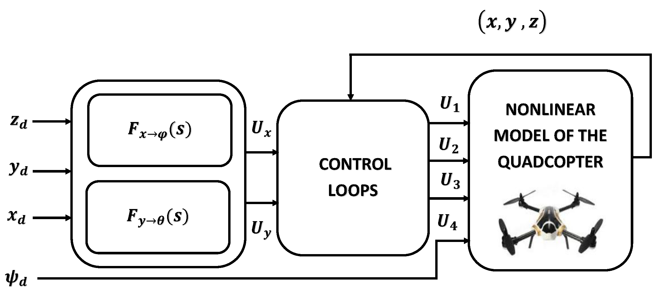
4. Trajectory Tracking via Attitude Stabilization

In this section, a new strategy for trajectory tracking via attitude stabilization is described. Different from the previous approach, where the problem of under actuation is solved using hierarchical controllers, this strategy is based on controlling the quadcopter position (y, x) through pitch and roll stabilization. The synoptic scheme of this new approach is illustrated in Figure 3.
Four parameters are mainly controlled (the altitude and the three angles of rotation). The stabilization of the other two positions ( x , y ) results from a judicious choice of roll and pitch inputs. The relations between positions (y, x) and rotations (pitch, roll) are deduced from the natural flight of the quadcopter.
In fact, to move the quadcopter in a direction x (or y), we must first act to obtain a rotation of roll (or pitch). If this rotation is constant or increasing, the drone will move indefinitely. On the other hand, if we wish to reach a given position, we must reduce the control of the rotations to zero [30].
The rapport between x (y) position and roll (pitch) attitude is modeled by the ratio of the roll (pitch) model function to the x ( y ) position model function. In natural flight, when the roll attitude is stable, the position x diverges. In this case, roll and x position behaviors with respect to a unit input can be modeled as follows:
ϕ ( s ) = K 1 ( 1 + T s ) s X ( s ) = K 2 e T 0 s s 2 .
Thus, the transfer x ϕ is given by (28).
F x ϕ ( s ) = ϕ ( s ) X ( s ) = K 1 s K 2 e T 0 s ( 1 + T s )
where { K 1 , K 2 , T , T 0 } are the adjustable model’s parameters, the transition from y position to pitch can be modeled in the same way.
According to Figure 3, firstly, four PDs/PIDs controllers are achieved to stabilize the altitude and the three attitude angles. In a second step, we connect the entries ϕ d and θ d to the corresponding transfer blocks. Instead of diverging signals, we get x and y positions which are also stable.
The PD/PID gains’ of the four controllers are designed by using reference model and genetic algorithm methods, which are detailed in the following subsections.

4.1. Trajectory Tracking Using the Reference Model Method (TTRM)

The controller described in the previous section is composed of a block of PD/PID controllers that stabilize the quadcopter attitude, consequently maintaining the position.
As described in Section 3.1, by setting some specifications for our reference system, the quadcopter UAV must behave in the same way. We aim to have a stabilization time for all four quadcopters T s = 0.5 s , without overshoot.
To perform this design, we consider the attitude and altitude transfer functions given in (14) which are rewritten in (29).
F ϕ ( s ) = ϕ ( s ) U 2 ( s ) = l I x s 2 F θ ( s ) = θ ( s ) U 3 ( s ) = l I y s 2 F ψ ( s ) = ψ ( s ) U 4 ( s ) = 1 I z s 2 F z ( s ) = z ( s ) U 1 ( s ) = k z s ( τ z s + 1 ) .
A PD/PID controller is introduced for each flight parameter, ϕ , θ , ψ , and z (30,31).
C P D j ( s ) = U i ( s ) j d j ( s ) = k p j + k d j s
C P I D j ( s ) = U i ( s ) j d j ( s ) = k p j + k i j s + k d j s
k p j , k i j , and k d j are the proportional, integral, and derivative gains, respectively, with j = ϕ , θ , ψ , z . The characteristic polynomials of the controlled systems are represented by Equations (20) and (21) and D z ( s ) in Equations (18) and (19). The obtained parameters are summarized in Table 3.

4.2. Trajectory Tracking Using Genetic Algorithms Method (TTGA)

Genetic algorithm techniques are used to optimize the PD/PID controllers’ parameters for the attitude and the altitude stabilization.
A vector of eight elements in the PD controllers case and twelve elements in the PIDs case is considered as an individual among a population of solutions to be optimized by utilizing the genetic algorithms. Each element of this vector represents a PD/PID controller’s parameter. The initial population is generated randomly in the following ranges: k p i [ 0 200 ] and k p i [ 0 50 ] for the PD parameters, while for the PID parameters: k p i [ 0 50 ] , k i i [ 0 20 ] and k d i [ 0 10 ] ;
To evaluate individuals of the population, a fitness function is indispensable. Relative to the purpose of this part of our work, the chosen fitness function takes into account the position stability that is required for a proper desired trajectory tracking, in addition to the attitude performance. The function expression taken in this part is given by (32).
f = 1 exp ( α D + β T s + γ E s s ) .
Here, T s is the settling time, E s s is the steady-state error, and D is the overshoot; α , β , and γ are weighting factors ( α = 10 ; β = 4 ; γ = 2 ) .
The obtained parameters values are summarized in the Table 4.
The simulation results of this subsection and the previous one, for the non-linear system represented by the dynamic model (1)–(6) coupled with the four controllers PD/PID, whose gains are recapitulated in Table 4 and Table 5, are shown in Section 5.

5. Simulation Results

In order to test the performance and efficiency of the proposed control strategies, two trajectory-tracking scenarios were used to simulate the performance of the proposed controllers.
First, the hierarchical controller and the trajectory tracking via attitude stabilization controller were tested in the absence of disturbances. In these simulations, the two proposed controllers were examined for a set point hovering flight, and then for a flight following a circular trajectory. The gains of the PD/PID controllers were calculated using the RM for the first time, and then optimized by utilizing GA optimization techniques, so that a comparative study between these two methods of synthesis can take place.
Second, the robustness of the hierarchical controller and the new control strategy proposed in this work were approved in an environment with disturbances.
Initially, the values of all the flight parameters are set to zero. The quadcopter parameter values used for simulation are mentioned in Table 5.

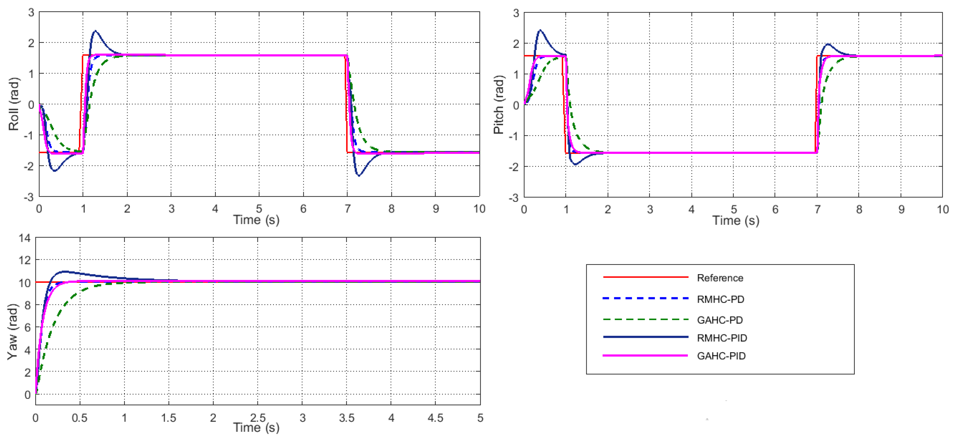
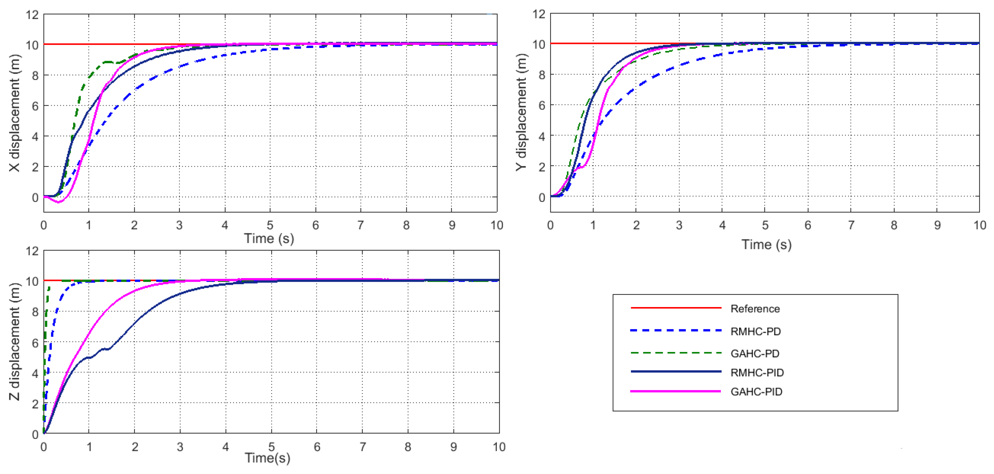
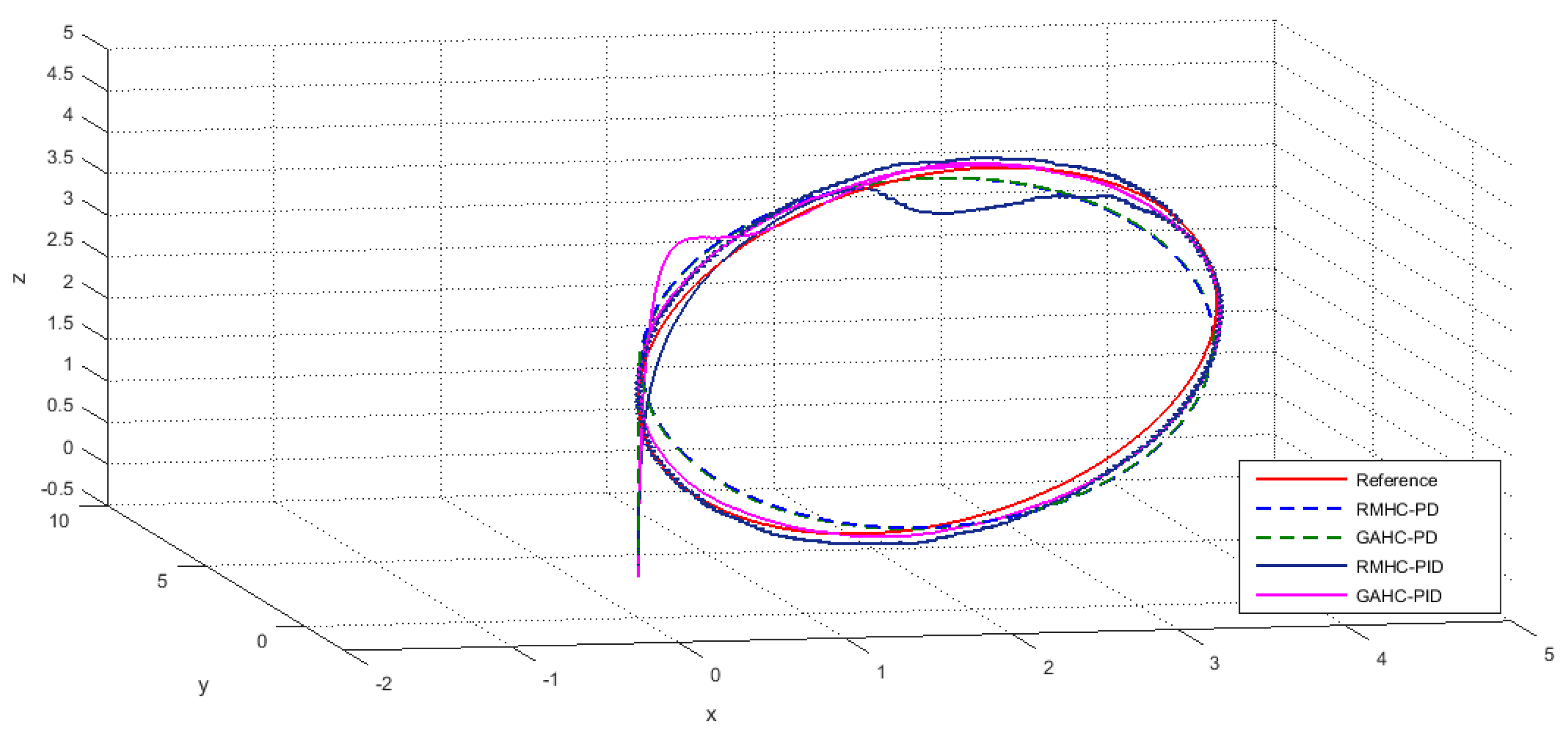
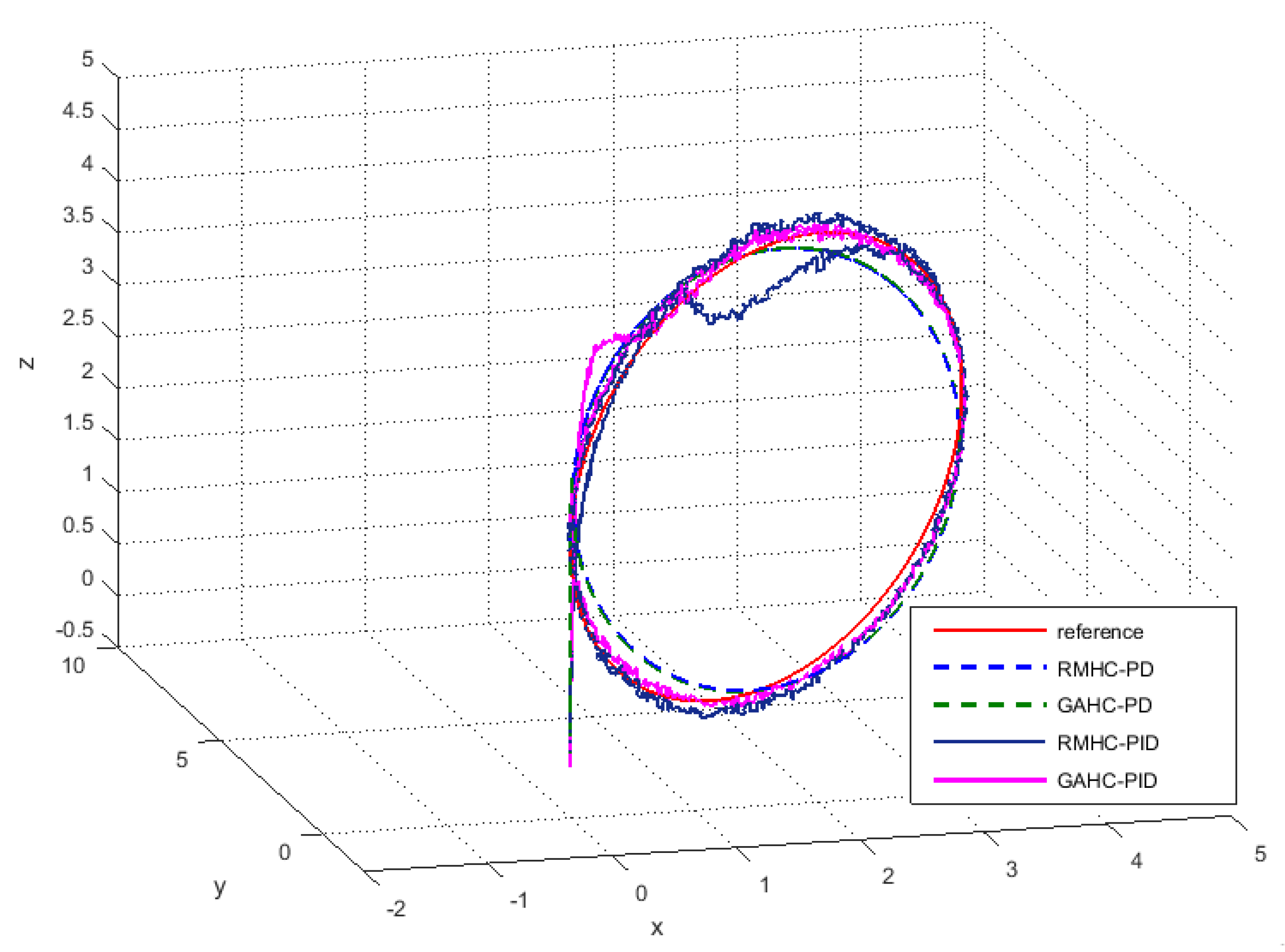
5.1. Hierarchical Controllers for Trajectory Tracking

The GA was applied in the hierarchical controller to tune the PD/PID gains firstly for the inner loop and then for the outer loop. However, in the RMHC, the PD/PID gains were determined by using the RM method separately for the inner and the outer system’s loops.
It is clearly shown in Figure 4 that the proposed hierarchical controller achieves accurate reference tracking with different settling time values. For the x and y positions, the RMHC-PD controller drives the system to the desired reference in three second without overshoot. In comparison, the use of PID controllers instead of PD for RMHC makes these flight parameters respond faster. Conversely, PD controllers in GAHC offer better performance with a settling time of 1.5 s for the x and y positions and 0.3 s for the altitude, z. Regarding the altitude, z, the settling time is faster and equal to 0.5 s with RMHC-PD, instead of 3 s with RMHC-PID.
Turning to the attitude responses presented in Figure 5, the PID controllers give faster responses than PD in both cases (GAHC and RMHC). On the other hand, PID controllers in RMHC provide an overshoot in the corrected attitude behavior. Differently, in GAHC, the use of PID controllers gives smooth and faster response, compared to PD. As we require in our specification a faster response without overshoot, the PD controllers are the more adequate when the reference method is adopted. As illustrated in Figure 6 and Figure 7, the second simulation for the hierarchical structure was carried out for a circular trajectory.
The tracking of a circular trajectory in 3D space is illustrated in Figure 8.
The quadrotor is initially located at the origin (0, 0, 0). Figure 8 shows that the quadrotor trajectory converges to the reference trajectory without trajectory deviations or changes of direction. The controlled quadcopter manages to accurately track the reference path and provides fast and accurate responses. From the aforementioned simulation results in two different cases (reference model PD/PID and genetic optimized PD/PID), we can conclude that the proposed hierarchical controller can achieve the given trajectory. Furthermore, PD controllers in hierarchical structure give better performance in terms of trajectory tracking, steady-state error, and overshoot compared to PID controllers. To conclude, the PD controllers in the hierarchical structure provide better results than the PID controllers.

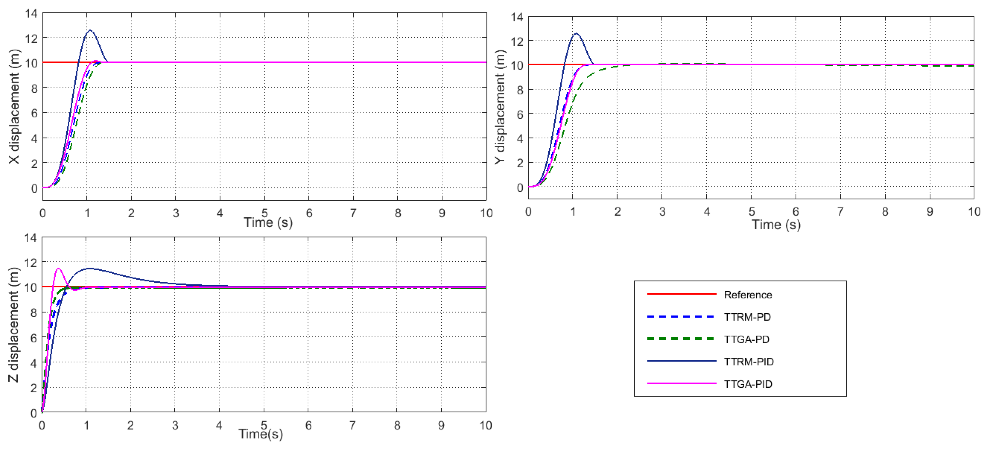
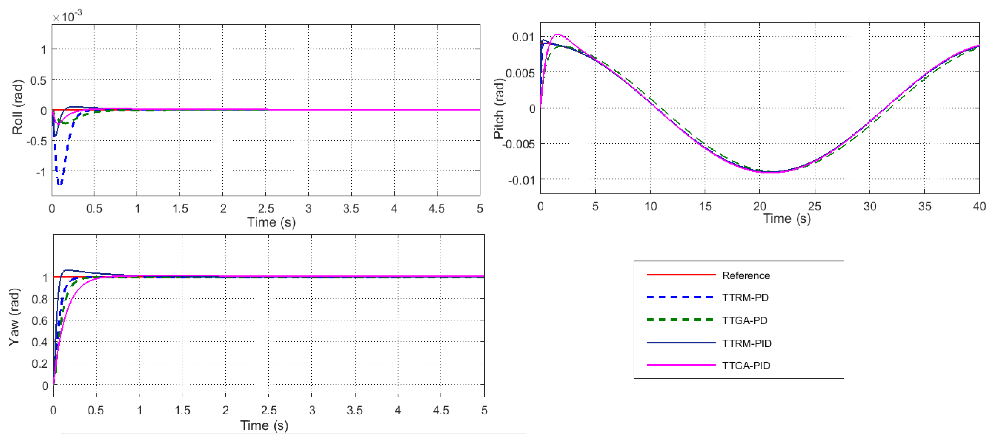
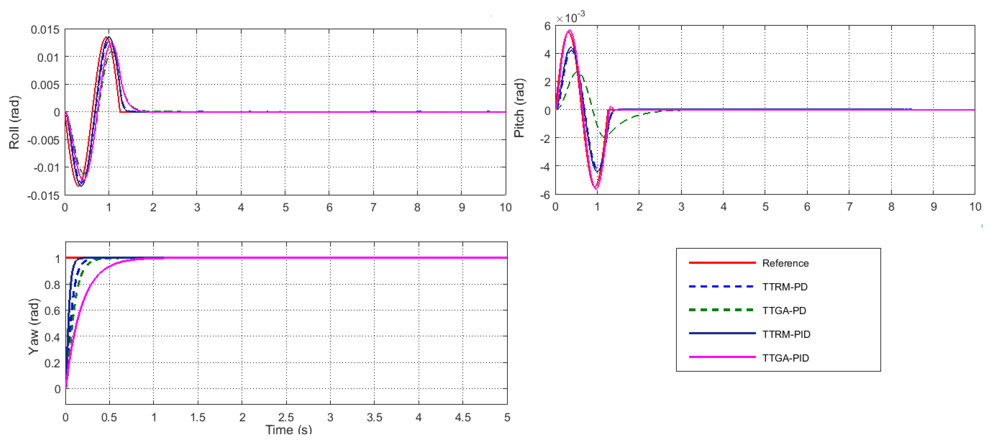
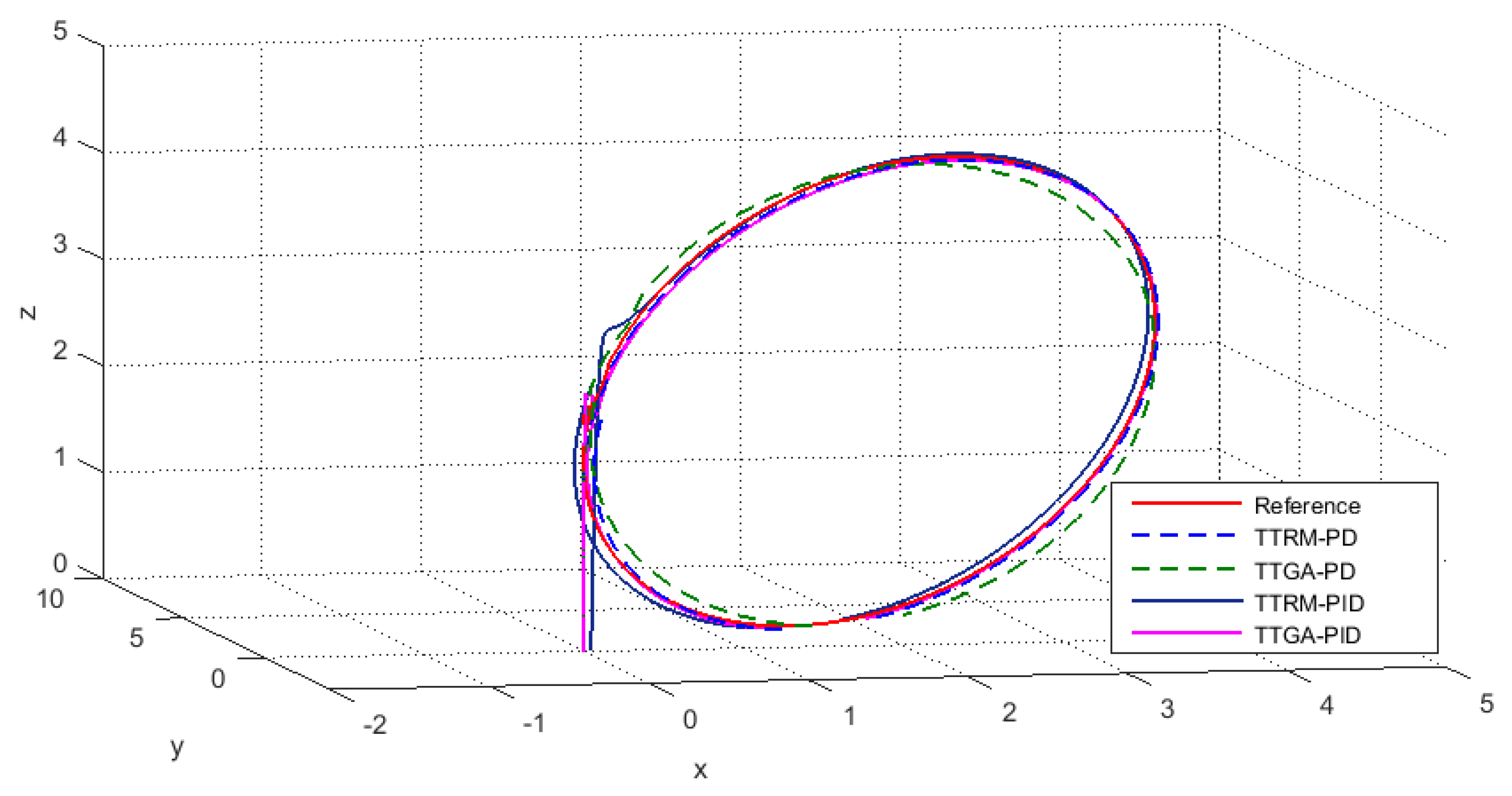
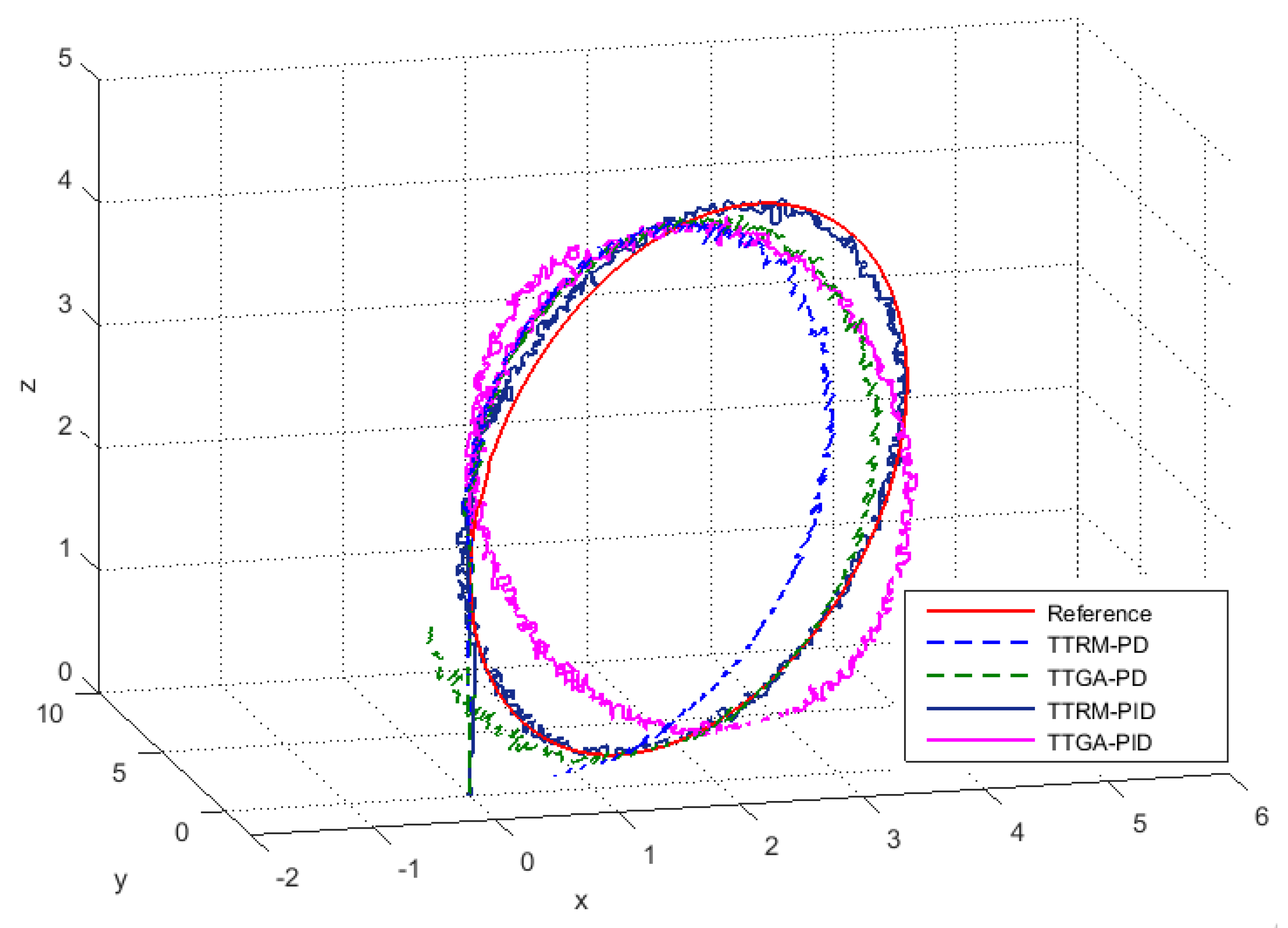
5.2. Trajectory Tracking via Attitude Stabilization

In this subsection, the results of the last performed simulations are presented.
Figure 9 shows the results of the position tracking, and as can be seen, the desired position is achieved. In both cases, the PD and PID controllers drive the quadcopter to the desired fixed point in a settling time of approximately 1 s with the PD controllers, and less than one second with the PID controllers. On the contrary, an overshoot of 30% is present in the x and y response, corrected by the PID controllers. These results were obtained after many trials to find out both the optimal and good-performing PD/PID controllers’ gains.
The attitude ( ϕ and θ ) behaviors corresponding to the position step response and the sinusoidal consign are presented in Figure 10 and Figure 11, respectively. Moreover, Figure 12 shows the tracking in each axis, so that each axis can be examined independently. As in the previous subsection, a simulation was performed for a circular trajectory to test the maneuverability and the validity of this proposed controller.
The 3D plot in Figure 13 illustrates a comparison between the reference trajectory and the actual controlled quadrotor trajectory. As in the previous trajectory tracking simulation, the quadcopter is located initially at the origin ( 0 , 0 , 0 ) . The quadrotor follows the desired path closely in the fourth cases (TTRM-PD, TTRM-PID, TTGA-PD, and TTGA-PID designs). In contrast, as mentioned above, the PID for the position (x and y) responses presented a higher overshoot. Therefore, it is preferred to adopt PD controllers for the trajectory tracking via attitude stabilization.
On the basis of these results, the new proposed strategy of trajectory tracking for quadcopter gives a good performance in term of settling time (less than 1 s) and state error when compared to the hierarchical strategy (Ts about 3 s).
In conclusion, the control methodology based on trajectory tracking via attitude stabilization was approved and its performance was tested.

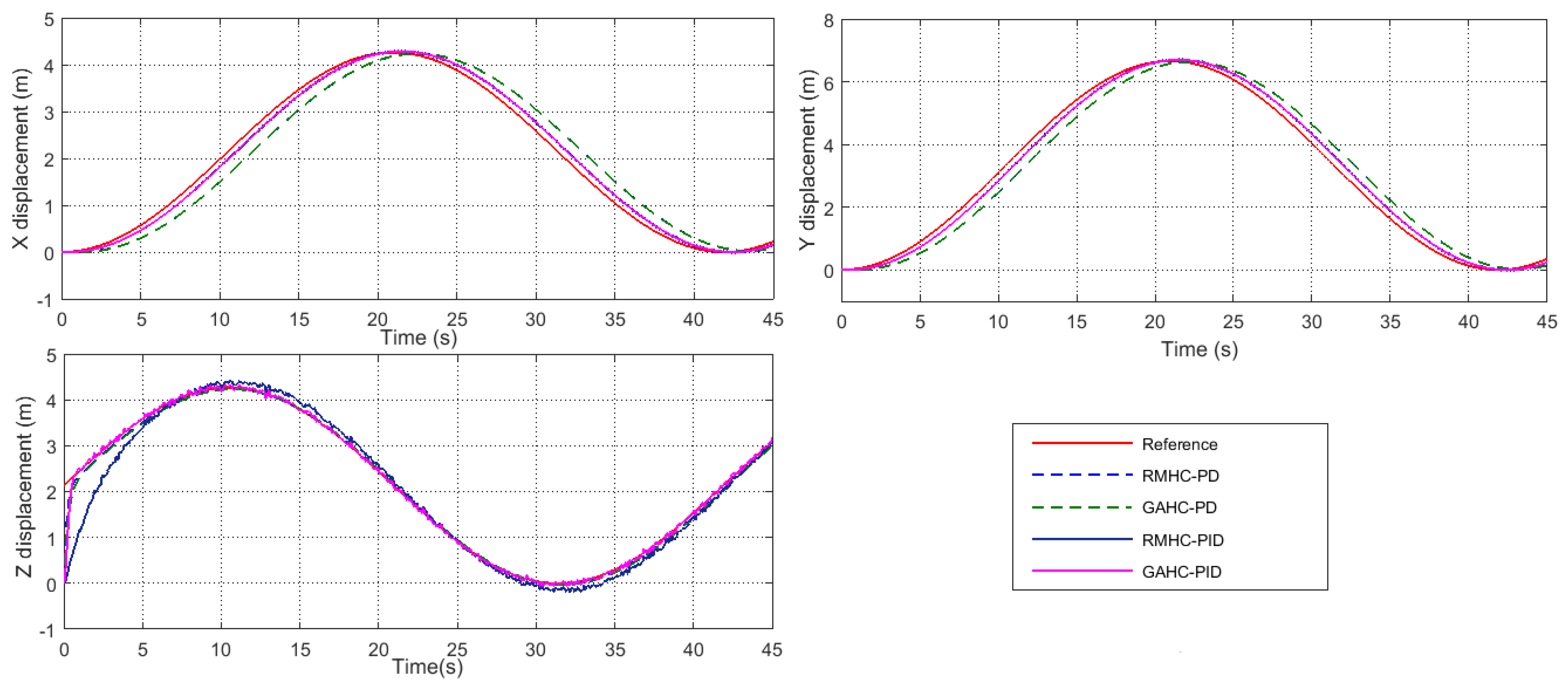
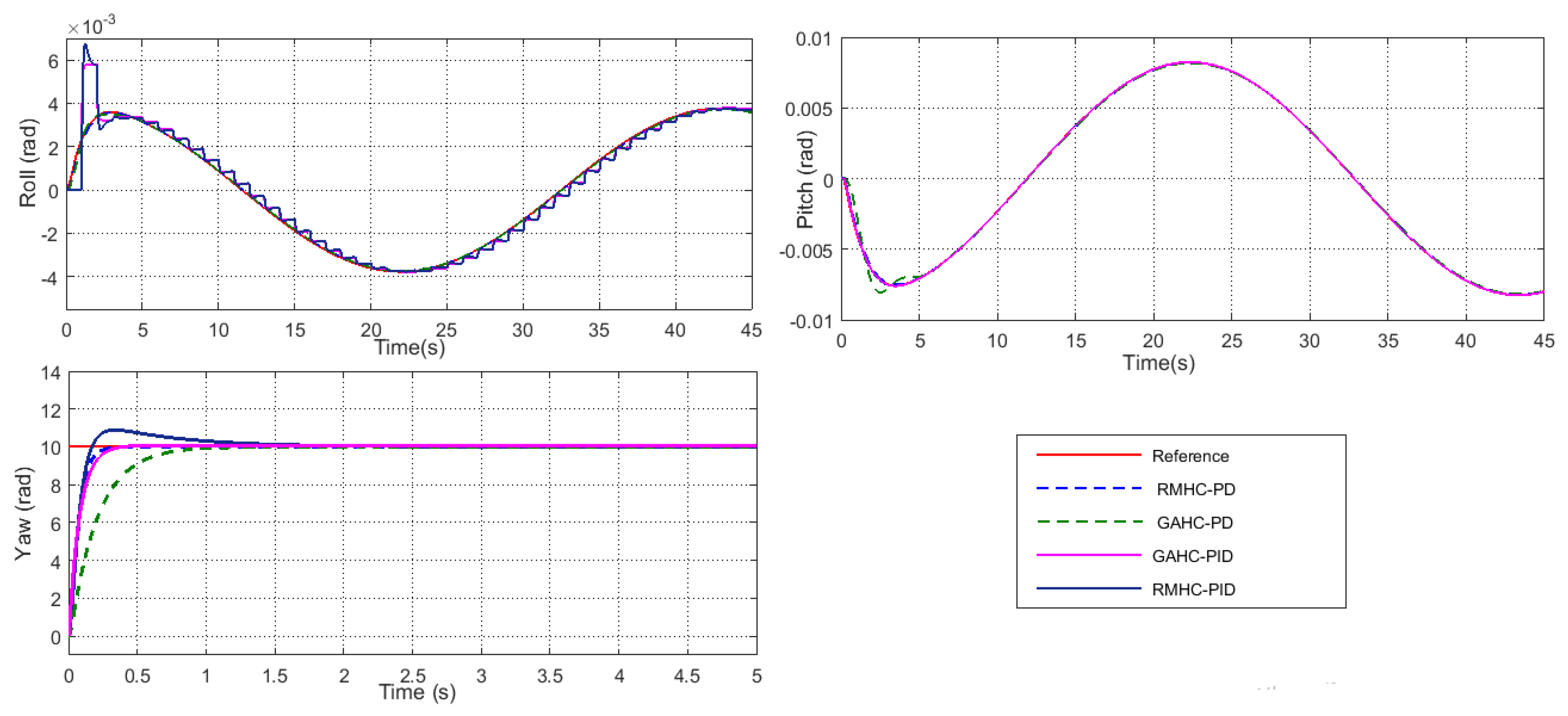
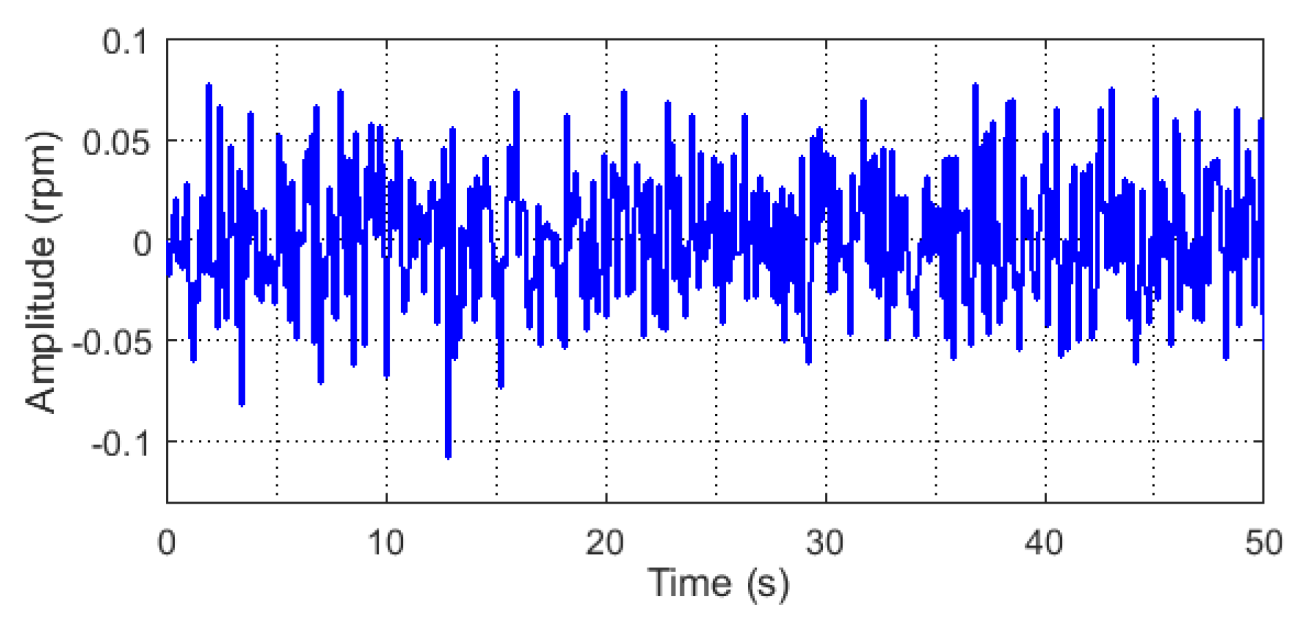
5.3. Trajectory Tracking in the Presence of Disturbance

During the flight, the quadcopter is subjected to external disturbances. The worst type of these are wind disturbances. These kind of disturbances can act on the rotors’ propellers affecting the rotors’ velocity. In our study, for this section, these kind of disturbances are modeled by a random signal with variable amplitude (Figure 14).
To analyze the robustness and the trajectory tracking performance of the proposed controllers, the disturbances presented in Figure 14 are considered as random variations in the four rotors speeds. In the simulink diagram representing the nonlinear model of the quadrocopter, these disturbances are injected as additive signals for the four inputs of the system ( U 1 , U 2 , U 3 , and U 4 ).

5.3.1. Hierarchical Controllers

The circular trajectory in the presence of disturbances is presented in Figure 15 and Figure 16. The flight following a circular trajectory in the presence of disturbances is presented in Figure 15 separately for each axis, and in a 3D view in Figure 16.
The results show that the RMHC and GAHC controllers can stabilize the quadcopter, and achieve the desired path in a disturbed environment. However, it can be clearly seen that for both strategies, PID controllers yield better performance in terms of eroor margin between the system response and the desired reference.

5.3.2. Trajectory Tracking via Attitude Stabilization

As in the previous subsection, Figure 17 and Figure 18 illustrate the trajectory tracking of a circular trajectory, where the system is in a disturbed environment.
These results show that the TTRM-PID and TTGA-PID controllers give the best responses, when compared to TTRM-PD and TTGA-PD in the presence of disturbances. In conclusion, the use of PD controllers is more suitable for this strategy of controller only in the absence of disturbances.

6. Conclusions

In this paper, to accomplish a high performing and robust controller for trajectory tracking; two different methods were developed and applied in two different controller strategies. First, the dynamic model of the quadcopter derived from the Newton–Euler and the Euler–Lagrange equations was presented. Then, the hierarchical strategy was employed in controller design to drive the quadcopter through a desired trajectory. This controller is composed of an inner loop for attitude stabilization and an outer loop for position control. These loops are a set of PD/PID controllers, in which the gains were determined firstly using the RM method, then, optimized by utilizing GA techniques. This paper also presents a novel control strategy to deal with the under actuation of the system studied. This strategy consists of trajectory tracking via attitude stabilization, driving the quadcopter towards the desired trajectory only by adjusting the system’s orientation. As with the first developed controller, this later was synthesized by using both methods (RM and GA). The performance of the proposed controllers was validated through extensive numerical simulations using the Matlab-Simulink environment. The results of the RMHC-PD/TTRM-PD and GAHC-PD/TTGA-PD controllers were compared to the RMHC-PID/TTRM-PID and GAHC-PID/TTGA-PID controllers. In hierarchical structure, the results demonstrate that PD controllers in the inner loop and PID controllers in the outer loop provide better performance. For trajectory tracking via attitude stabilization, PD improves responses in the absence of disturbances. In conclusion, the quadrotor achieves the desired conditions in both set point hovering flight and path following flight in hierarchical structure and trajectory tracking via attitude stabilization.
In both cases (the hierarchical controller and trajectory tracking via attitude stabilization), the disturbances affect the quadcopter position, but within acceptable boundaries, which allow the quadcopter to not lose track of the reference trajectory. In conclusion, the robustness of all proposed controllers was tested and validated in spite of disturbances. The objective of developing an effective and robust trajectory tracking control system for a quadcopter in the presence of disturbances has been achieved.

Author Contributions

Data curation, I.S.; Investigation, I.S. and M.M.; Methodology, I.S. and M.M.; Resources, I.S.; Supervision, M.M., H.A. and A.E.K.; Validation, M.M.; Writing—original draft, I.S.;Writing—review and editing, I.S. and M.M.

Funding

This research received no external funding.

Conflicts of Interest

The authors declare no conflict of interest.

Abbreviations

The following abbreviations are used in this manuscript:
PDProportional, Derivative
PIDProportional, Integral, Derivative
GAGenetic Algorithm
RMReference Model
RMHCReference Model besed Hierarchical Controller
GAHCGenetic Algorithm besed Hierarchical Controller
TTRMTrajectory Tracking by using Reference Model
TTGATrajectory Tracking by using Genetic Algorithm

References

  1. Zhang, Y.; Kondak, K.; Lu, T.; Du, J.; Bernard, M.; Wang, G. Development of the model and hierarchy controller of the quad-copter. Proc. Inst. Mech. Eng. Part G J. Aerosp. Eng. 2008, 222, 1–12. [Google Scholar] [CrossRef]
  2. Mercado, D.; Castillo, P.; Castro, R.; Lozano, R. 2-Sliding Mode Trajectory Tracking Control and EKF Estimation for Quadrotors. IFAC Proc. Vol. 2014, 47, 8849–8854. [Google Scholar] [CrossRef]
  3. Zou, Y. Nonlinear robust adaptive hierarchical sliding mode control approach for quadrotors. Int. J. Robust Nonlinear Control 2017, 27, 925–941. [Google Scholar] [CrossRef]
  4. Wang, L.; Jia, H. The trajectory tracking problem of quadrotor UAV: Global stability analysis and control design based on the cascade theory. Asian J. Control 2014, 16, 574–588. [Google Scholar] [CrossRef]
  5. Cabecinhas, D.; Cunha, R.; Silvestre, C. A nonlinear quadrotor trajectory tracking controller with disturbance rejection. Control Eng. Pract. 2014, 26, 1–10. [Google Scholar] [CrossRef]
  6. Dong, W.; Gu, G.Y.; Zhu, X.; Ding, H. High-performance trajectory tracking control of a quadrotor with disturbance observer. Sens. Actuators A 2014, 211, 67–77. [Google Scholar] [CrossRef]
  7. Sun, L.; Zuo, Z. Nonlinear adaptive trajectory tracking control for a quad-rotor with parametric uncertainty. Proc. Inst. Mech. Eng. Part G J. Aerosp. Eng. 2015, 229, 1709–1721. [Google Scholar] [CrossRef]
  8. Zuo, Z.; Wang, C. Adaptive trajectory tracking control of output constrained multi-rotors systems. IET Control Theory Appl. 2014, 8, 1163–1174. [Google Scholar] [CrossRef]
  9. Nguyen, N.P.; Hong, S.K. Sliding Mode Thau Observer for Actuator Fault Diagnosis of Quadcopter UAVs. Appl. Sci. 2018, 8, 1893. [Google Scholar] [CrossRef]
  10. Khebbache, H.; Tadjine, M. Robust fuzzy backstepping sliding mode controller for a quadrotor unmanned erial vehicle. J. Control Eng. Appl. Inform. 2013, 15, 3–11. [Google Scholar]
  11. Khalili, B.; Rezaei, M. Trajectory tracking control of a quadrotor via fuzzy terminal sliding mode controller in the presence of uncertainty. Bull. Soc. R. Sci. Liege 2016, 85, 227–237. [Google Scholar]
  12. Nafia, N.; El Kari, A.; Ayad, H.; Mjahed, M. Robust Full Tracking Control Design of Disturbed Quadrotor UAVs with Unknown Dynamics. Aerospace 2018, 5, 115. [Google Scholar] [CrossRef]
  13. Su, X.; Wu, Y.; Song, J.; Yuan, P. A Fuzzy Path Selection Strategy for Aircraft Landing on a Carrier. Appl. Sci. 2018, 8, 779. [Google Scholar] [CrossRef]
  14. Chen, Y.M.; He, Y.L.; Zhou, M.F. Decentralized PID neural network control for a quadrotor helicopter subjected to wind disturbance. J. Cent. South Univ. 2015, 22, 168–179. [Google Scholar] [CrossRef]
  15. El Hamidi, K.; Mjahed, M.; El Kari, A.; Ayad, H. Neural and Fuzzy Based Nonlinear Flight Control for an Unmanned Quadcopter. Int. Rev. Autom. Control (IREACO) 2018, 11, 98–106. [Google Scholar] [CrossRef]
  16. Estevez, J.; Graña, M. Robust Control Tuning by PSO of Aerial Robots Hose Transportation; LNCS Springer: Cham, Switzerland, 2015; Volume 9108, pp. 291–300. [Google Scholar]
  17. El Gmili, N.; Mjahed, M.; El Kari, A.; Ayad, H. An Improved Particle Swarm Optimization (IPSO) Approach for Identification and Control of Stable and Unstable Systems. Int. Rev. Autom. Control (IREACO) 2017, 10, 229–239. [Google Scholar] [CrossRef]
  18. Tran, H.-K.; Chiou, J.-S. PSO-Based Algorithm Applied to Quadcopter Micro Air Vehicle Controller Design. Micromachines 2016, 7, 168. [Google Scholar] [CrossRef] [PubMed]
  19. Siti, I.; Mjahed, M.; Ayad, H.; El Kari, A. New Designing Approaches for Quadcopter PID Controllers Using Reference Model and Genetic Algorithm Techniques. Int. Rev. Autom. Control (IREACO) 2017, 10, 240–248. [Google Scholar] [CrossRef]
  20. Wilburn, K.B.; Perhinschi, G.M.; Wilburn, N.J. A modified genetic algorithm for UAV trajectory tracking control laws optimization. Int. J. Intell. Unmanned Syst. 2014, 2, 58–90. [Google Scholar] [CrossRef]
  21. Castillo, P.; Dzul, A.; Lozano, R. Real-time stabilization and tracking of a four rotor mini-rotorcraft. IEEE Trans. Control Syst. Technol. 2003, 12, 3123–3128. [Google Scholar]
  22. Basri, M.A.; Husain, A.R.; Danapalasingam, K.A. Backstepping controller with intelligent parameters selection for stabilization of quadrotor helicopter. J. Eng. Sci. Technol. Rev. 2014, 7, 66–74. [Google Scholar] [CrossRef]
  23. Alexis, K.; Nikolakopoulos, G.; Tzes, A. Model predictive quadrotor control: Attitude, altitude and position experimental studies. IET Control Theory A 2012, 6, 1812–1827. [Google Scholar] [CrossRef]
  24. Efe, M. Neural Network Assisted Computationally Simple PI λ D μ Control of a Quadrotor UAV. IEEE Trans. Ind. Inf. 2011, 7, 354–361. [Google Scholar] [CrossRef]
  25. Xu, R.; Özgüner, Ü. Sliding mode control of a class of underactuated systems. Automatica 2008, 44, 233–241. [Google Scholar] [CrossRef]
  26. Smith, C.A.; Corripio, A.B. Principles and Practice of Automatic Process Control; Wiley: New York, NY, USA, 1985; Volume 2. [Google Scholar]
  27. Bertrand, S.; Guénard, N.; Hamel, T.; Piet-Lahanier, H.; Eck, L. A hierarchical controller for miniature VTOL UAVs: Design and stability analysis using singular perturbation theory. Control Eng. Pract. 2011, 19, 1099–1108. [Google Scholar] [CrossRef]
  28. Mjahed, M. Commande des Systemes; Lectures Notes; Ecole Royale de l’Air: Marrakech, Morocco, 2016. [Google Scholar]
  29. Mjahed, M. Asservissements Lineaires Continus; Lectures Notes; Ecole Royale de l’Air: Marrakech, Morocco, 2014. [Google Scholar]
  30. Sa, I.; Corke, P. Vertical infrastructure inspection using a quadcopter and shared autonomy control. In Field and Service Robotics; Springer: Berlin/Heidelberg, Germany, 2014; pp. 219–232. [Google Scholar]
Figure 1. Quadrotor shape, frame system with a body fixed frame B and the inertial frame E.
Applsci 09 01780 g001
Figure 2. Synoptic scheme of the proposed hierarchical control strategy.
Applsci 09 01780 g002
Figure 3. Synoptic scheme of the proposed trajectory tracking via attitude stabilization strategy.
Applsci 09 01780 g003
Figure 4. Quadcopter position step response obtained by RMHC and GAHC approaches.
Applsci 09 01780 g004
Figure 5. Quadcopter attitude step response obtained using the RMHC and GAHC approaches.
Applsci 09 01780 g005
Figure 6. Quadcopter position trajectory tracking performed using the RMHC and GAHC approaches.
Applsci 09 01780 g006
Figure 7. Quadcopter attitude trajectory tracking performed using the RMHC and GAHC approaches.
Applsci 09 01780 g007
Figure 8. Quadcopter tracking of a circular trajectory in 3D space (solid red line) performed using the RMHC and GAHC approaches.
Applsci 09 01780 g008
Figure 9. Quadcopter position step response achieved via attitude stabilization, on the basis of the TTRM and TTGA approaches.
Applsci 09 01780 g009
Figure 10. Quadcopter attitude response (corresponding to step consign for the position) achieved via attitude stabilization, on the basis of the TTRM and TTGA approaches.
Applsci 09 01780 g010
Figure 11. Quadcopter attitude response (corresponding to sinusoidal consign for the position) achieved via attitude stabilization, on the basis of the TTRM and TTGA approaches.
Applsci 09 01780 g011
Figure 12. Quadcopter position trajectory tracking using the TTRM and TTGA approaches.
Applsci 09 01780 g012
Figure 13. Quadcopter tracking of a circular trajectory in 3D space (solid red line) achieved using the TTRM and TTGA approaches.
Applsci 09 01780 g013
Figure 14. Disturbance signal.
Applsci 09 01780 g014
Figure 15. Quadcopter position trajectory tracking performed using the RMHC and GAHC approaches in the presence of disturbances.
Applsci 09 01780 g015
Figure 16. Quadcopter tracking of a circular trajectory in 3D space (solid red line) performed using the RMHC and GAHC approaches in the presence of disturbances.
Applsci 09 01780 g016
Figure 17. Quadcopter position trajectory tracking using TTRM and TTGA (PD/PID) in the presence of disturbances.
Applsci 09 01780 g017
Figure 18. Quadcopter tracking of a circular trajectory in 3D space (solid red line) achieved using TTRM and TTGA (PD/PID) in the presence of disturbances.
Applsci 09 01780 g018
Table 1. Proportional-derivative (PD) and proportional-integral-derivative (PID) parameters values of the reference model-based hierarchical control (RMHC).
RMHC MethodControllers
C ϕ ( s ) C θ ( s ) C ψ ( s ) C x ( s ) C y ( s ) C z ( s )
PD
Parameters
k p 16.6716.6716.670.100.10190.8
k d 1.211.211.210.200.2034.98
PID
Parameters
k p 37.1737.1733.3418.3437.176.60
k i 65.2265.227.280.2565.220.05
k d 2.352.351.410.412.356.24
Table 2. PD and PID parameters values of the genetic algorithm hierarchical control (GAHC).
GAHC MethodControllers
C ϕ ( s ) C θ ( s ) C ψ ( s ) C x ( s ) C y ( s ) C z ( s )
PD
Parameters
k p 16.8315.7822.827.927.41184.0
k d 2.822.5542.486.456.4023.05
PID
Parameters
k p 48.6335.8334.1813.347.6117.67
k i 8.451.367.570.160.920.10
k d 2.292.356.505.235.4610.40
Table 3. PD and PID parameters values synthesized by reference model method for trajectory tracking using the reference model (TTRM).
TTRM MethodControllers
C ϕ ( s ) C θ ( s ) C ψ ( s ) C z ( s )
PD
Parameters
k p 16.6716.6716.67190.8
k d 1.271.271.2734.98
PID
Parameters
k p 23.4823.4842.3829.01
k i 13.5813.580.8123.58
k d 1.421.421.718.58
Table 4. PD and PID Parameters values synthesized by genetic algorithm optimization for trajectory tracking using the genetic algorithm (TTGA).
TTGA MethodControllers
C ϕ ( s ) C θ ( s ) C ψ ( s ) C z ( s )
PD
Parameters
k p 17.536.1310.33176.91
k d 2.592.921.0345.55
PID
Parameters
k p 27.7323.9234.1821.85
k i 17.8613.521.7112.51
k d 3.430.686.315.25
Table 5. Physical parameters of the quadrotor unmanned aerial vehicle (UAV).
Parameter (Unit)Value
m (Kg)0.53
g (m/s 2 )9.81
l (m)0.4
b (N/rad/s)4.15 ×  10 5
d (N·m/rad/s)7.5 ×  10 7
I x , I y (Kg·m 2 )7.86 ×  10 3
I z (Kg·m 2 )1.173 ×  10 3
J r (Kg·m 2 )2.8385 ×  10 5
K f a x , K f a y , K f t x , K f t y (N/rad/s)5.567 ×  10 4
K f a z (N/rad/s)6.354 ×  10 4
K f t z (N/rad/s)3.354 ×  10 4

