Article

Development of Heat Dissipation Multilayer Media for Volumetric Magnetic Hologram Memory

1
Department of Electrical and Electronic Information Engineering, Toyohashi University of Technology, 1-1 Tempaku-cho, Toyohashi, Aichi 441-8580, Japan
2
Japan Science and Technology Agency, Precursory Research for Embryonic Science and Technology (JST PRESTO), 4-1-8 Honcho, Kawaguchi, Saitama 332-0012, Japan
*
Author to whom correspondence should be addressed.
Appl. Sci. 2019, 9(9), 1738; https://doi.org/10.3390/app9091738
Submission received: 29 March 2019 / Revised: 18 April 2019 / Accepted: 24 April 2019 / Published: 26 April 2019
(This article belongs to the Special Issue Applications of Magneto-Optical Materials)

Abstract

:

Featured Application

This work is aimed at realizing magnetic hologram data storage.

Abstract

Holographic memory is a strong candidate for next-generation optical storage, featuring high recording densities and data transfer rates, and magnetic hologram memory using a magnetic garnet, as the recording material is expected to be used as a rewritable and stable storage technology. However, the diffraction efficiency of magnetic holography depending on the Faraday rotation angle is insufficiently high for actual storage devices. To increase the diffraction efficiency, it is important to record deep magnetic fringes, whereas it is necessary to suppress the merging of fringes owing to heat diffusion near the medium surface. In this work, we investigated the recording process of magnetic holograms in detail with experiments and numerical simulations, and developed a multilayer media with transparent heat dissipation layers to record deep and clear magnetic holograms by controlling the heat diffusion generated during the thermomagnetic recording process. To suppress lateral heat diffusion near the medium surface, we designed and fabricated a multilayer magnetic medium in which the recording magnetic layers are discrete in a film, approximately 12-µm thick. This medium exhibited diffraction efficiency higher than that of the single-layer medium, and error-free recording and reconstruction were achieved using the magnetic assist technique.

1. Introduction

Holographic memory has been attracting attention as a data-storage technology with high recording density and data transfer rates because two-dimensional (2D) page data can be recorded and read selectively from a single position [1,2,3,4,5,6,7,8,9,10,11]. The Holographic Versatile Disk is an international standard for holographic memory and employs a collinear holographic system that can write and read data using a single optical axis with a spatial light modulator as the key device [12,13,14]. Most holographic memories use refractive-index-modulation-type photopolymers, whereas photopolymer-based hologram media can only be written once. In contrast, the magnetic hologram is a candidate for rewritable holograms and exhibits a high material stability, in which the interference patterns of light can be recorded as differences in the direction of magnetization; interference patterns have been recorded on thin films of MnBi and TbFe alloys as magneto-optical recording materials [15,16,17,18].
A magnetic hologram is recorded using the thermomagnetic recording technique (Figure 1). When focused signal and reference beams were incident on a perpendicularly magnetized film, the light interference produces an intensity distribution in the order of the wavelength of light in the film. As a result, absorption of light produces a temperature distribution in the film corresponding to the interference pattern (Figure 1a,b). The magnetization of the heated region above the Curie temperature is reversed during cooling by stray and external magnetic fields (Figure 1c,d). By using this mechanism, the interference pattern of light can be recorded as differences in the direction of magnetization of the magnetic material in the magnetic hologram. To achieve a temperature distribution that corresponds to an interference fringe, the irradiation time of the laser beam must be sufficiently short to suppress thermal diffusion during irradiation [19]. A written hologram can be reconstructed by a magneto-optical effect such as the Faraday effect [15,16,17,18,19,20,21], and a large Faraday rotation angle results in a bright reconstruction image.
We have conducted studies to realize magnetic hologram memory using polycrystalline magnetic garnet films such as bismuth-substituted rare-earth iron garnet (Bi:RIG), which has a sufficient transparency and long-term stability [19,21,22,23,24,25,26,27]. In the garnet films, volumetric magnetic holograms can be recorded with a high resolution because polycrystalline garnet films can have small magnetic domains originating from the crystal grains by the weak magnetic coupling between grains [28]. As a result, we have succeeded in recording 2D data and reconstructing them from the magnetic hologram without error [26,27], whereas the diffraction efficiency of magnetic garnet films, an index for the brightness of an image, would not be sufficient for application to actual storage devices. The diffraction efficiency of magnetic holograms, η, can be theoretically expressed as:
η T sin 2 ( θ F × d / t ) T ( θ F × d / t ) 2 ,
where T is the transmittance, θF is the Faraday rotation angle of the medium, d is the depth of the magnetic fringe, and t is the thickness of the medium [18]. Because the light intensity of the reconstruction image of the magnetic hologram depends on the diffraction efficiency, it is desirable to record a deep magnetic hologram in the recording material that has a large Faraday rotation angle and appropriate transmissivity according to Equation (1). To enhance the diffraction efficiency, one can use magnetophotonic microcavities or magnetophotonic crystals as recording media because of the higher Faraday rotation angle and depth of the formed magnetic fringes [22,23,24]. High diffraction efficiencies can also be achieved by forming deep fringes even for the same recording material. However, thermomagnetic writing with a high incident optical power for forming deep magnetic fringes produces an excessively high temperature near the medium surface, so fringes become wider and merge with adjacent fringes near the surface. To suppress the heat diffusion effect and control the shapes of the fringes, a multilayer structure composed of Bi:RIG and transparent heat dissipation (HD) layers is effective for diffusing the excess heat from the garnet layers into the HD layers (HDLs) [25]. In this study, we investigated in detail the recording process of magnetic holograms in garnet media with experiments and numerical simulations in order to improve diffraction efficiency through forming deep and clear magnetic fringes. Finally, a simple design method for HD multilayer media was developed, and the HD multilayer medium was fabricated. Using this HD multilayer medium, the diffraction efficiency was evaluated, and 2D data were recorded and reconstructed using a collinear interferometer.

2. Materials and Methods

Bi:RIG single-layer and HD multilayer media were deposited on nonmagnetic substituted gadolinium gallium garnet (SGGG) substrates through the radio-frequency magnetron sputtering or ion beam sputtering. For Bi:RIG deposition, we used a target with the composition Bi:Dy:Y:Fe:Al = 1.5:1.0:1.0:3.8:1.2, and Tb3Ga5O12 (TGG) layers were also deposited as HDLs for the HD multilayer medium. The total thickness of the Bi:RIG layer(s) was approximately 3 µm. The deposited Bi:RIG was crystallized by rapid thermal annealing at 750 °C for 15 min in air because the as-deposited Bi:RIG was not crystallized.
Figure 2 illustrates the experimental setup of the two-beam interferometer to evaluate the diffraction efficiency and collinear interferometer to record and reconstruct the 2D data [27]. A pulsed laser with a wavelength of 532 nm and pulse width of 50 ps/pulse was used to record and reconstruct the magnetic holograms. The diffraction efficiency, η, was evaluated using:
η = I 1 I 0 + I 1 ,
where I0 and I1 are intensities of the zero-order transparent light and first-order diffracted light, respectively. The periods of the interference fringe were set to range from 500 line-pairs/mm to 1500 line-pairs/mm. A Helmholtz coil was used to apply an assist magnetic field in the direction opposite to the initial magnetization for enhancing the magnetization reversal. For data recording in the collinear system, 48 × 48 pixels with the 3:16 encoding method for the signal were used [26]. The reconstruction images were obtained by irradiating only the reference parts, and the pixel error ratio was evaluated. The recorded magnetic interference fringes with spatial frequencies of 500 line-pairs/mm and 1500 line-pairs/mm in the Bi:RIG medium were observed in the SPring-8 X-ray radiation facility. X-ray magnetic circular dichroism (XMCD) spectroscopy mapping using circularly polarized X-rays was performed at the BL39XU beam line at SPring-8. The X-ray energy was set to 7.11 keV, which is the Fe K absorption edge, and XMCD measurements were performed with the focused spot size of 100 × 300 nm2. Numerical analysis using COMSOL Multiphysics was also performed to clarify the formation mechanism of the magnetic fringe by thermomagnetic recording and the relationship between the fringe shape and the diffraction efficiency (see Appendix A in detail).

3. Results and Discussion

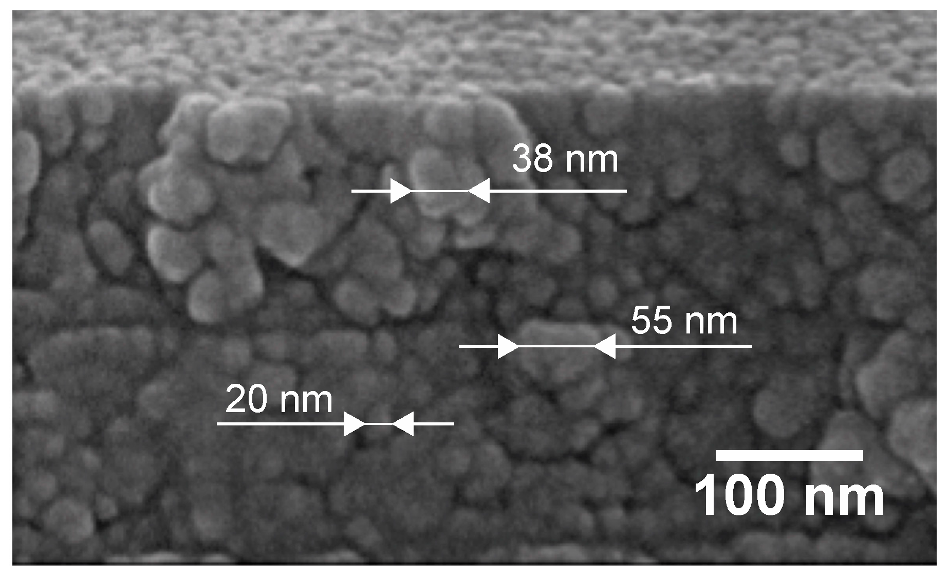
3.1. Garnet Film Morphology and Magnetic Fringe Shape

A typical cross-sectional view of the garnet film used in the experiments is shown in Figure 3 [21]. The polycrystalline garnet film consists of grains measuring 20–55 nm and is enough small to record the interference pattern of the collinear hologram with a sufficient resolution.
Figure 4 shows the experimentally and numerically obtained maximum diffraction efficiencies normalized to that of 500 line-pairs/mm against the spatial frequency of the fringes written in the 3-µm-thick Bi:RIG single-layer medium. The diffraction efficiency decreases with spatial frequency to approximately 20% at 1500 line-pairs/mm in both the experiment and simulation [19]. The simulation results are in good agreement with the experimental results, with the former being slightly larger than the latter.
This decrease in diffraction efficiency with spatial frequency could be because of the decrease in fringe depth [19]. In contrast, to investigate why the experimental diffraction efficiencies are lower than those of the simulation, direct observation of magnetic fringes was performed using X-ray radiation at SPring-8. Figure 5a shows an XMCD observation result of a 500 line-pairs/mm sample in which an interference fringe interval of approximately 2 μm was observed. As shown in the figure, contrast changes are observed at 2-μm intervals; this means that interference fringes could be observed with XMCD mapping. In contrast, in the case of the 1500 line-pairs/mm sample in which an interference fringe interval of 0.7 µm was observed, the interference fringes are not very clear, as shown in Figure 5b. To determine the reason for these results, the Fe Kα fluorescent X-ray intensity distribution simultaneously evaluated in the same location as that in Figure 5a is shown in Figure 5c. From this figure, the contrast, which indicates the concentration of Fe, is found to be nonuniform in the film, and the magnetic fringes observed in the XMCD image tend to be disturbed in the inhomogeneous part of the Fe composition. This suggests that composition fluctuations at a 1-μm scale or less may exist in the Bi:RIG film, and the compositional heterogeneity of this film is a factor influencing the heterogeneity observed in the XMCD image. In addition, by comparing the XMCD intensity of the uniformly magnetized region in the opposite direction to the intensity of the interference fringes, it was found that the magnetization of the magnetic fringes may not be completely reversed by thermomagnetic writing. These observation results indicate that compositional inhomogeneity exists in the Bi:RIG film and disturbs the precise recording of magnetic fringes. Therefore, the improving compositional homogeneity is needed for improving the shape of magnetic fringes, and magnetic assist recording is effective for increasing the magnetic fringe reversal.

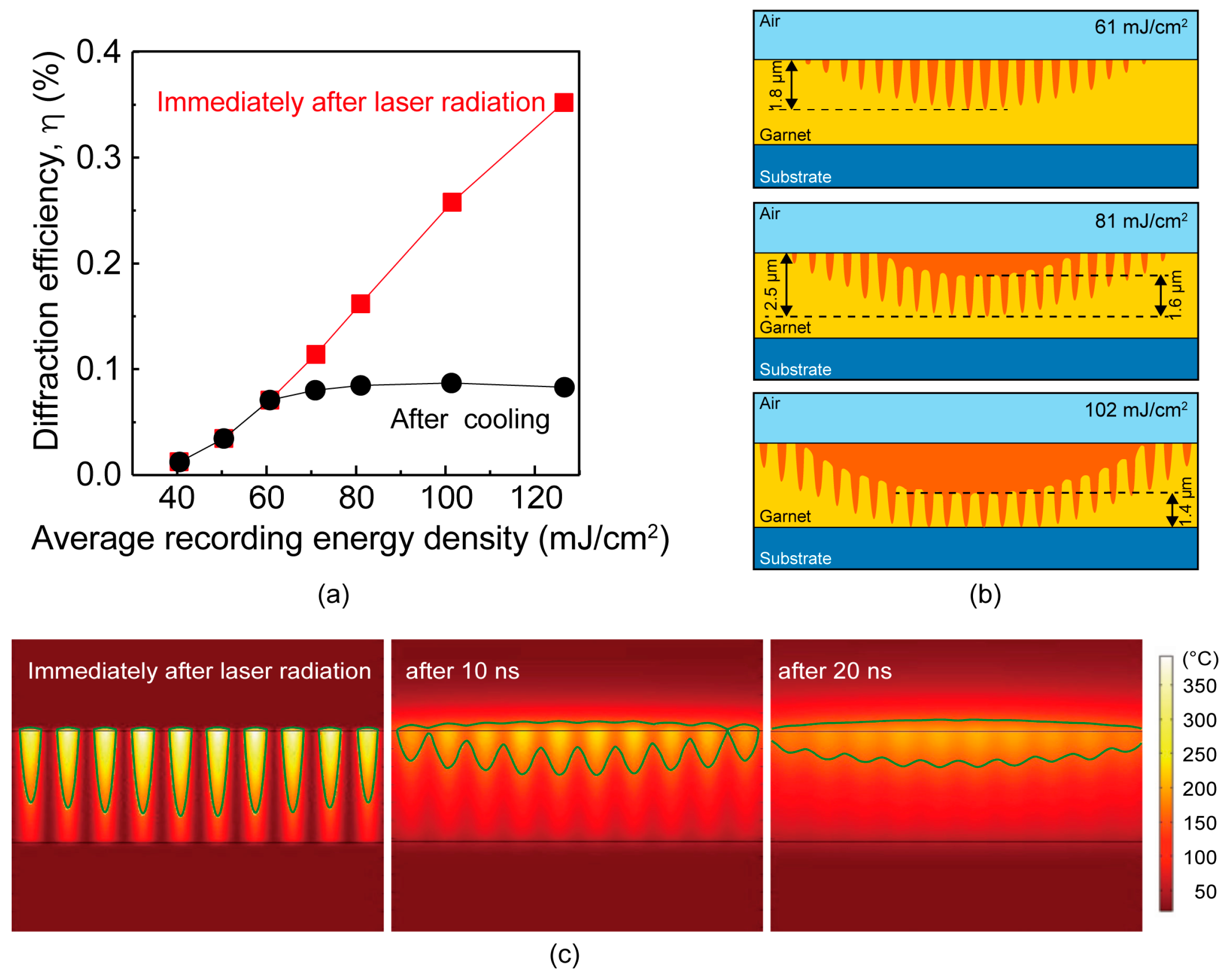
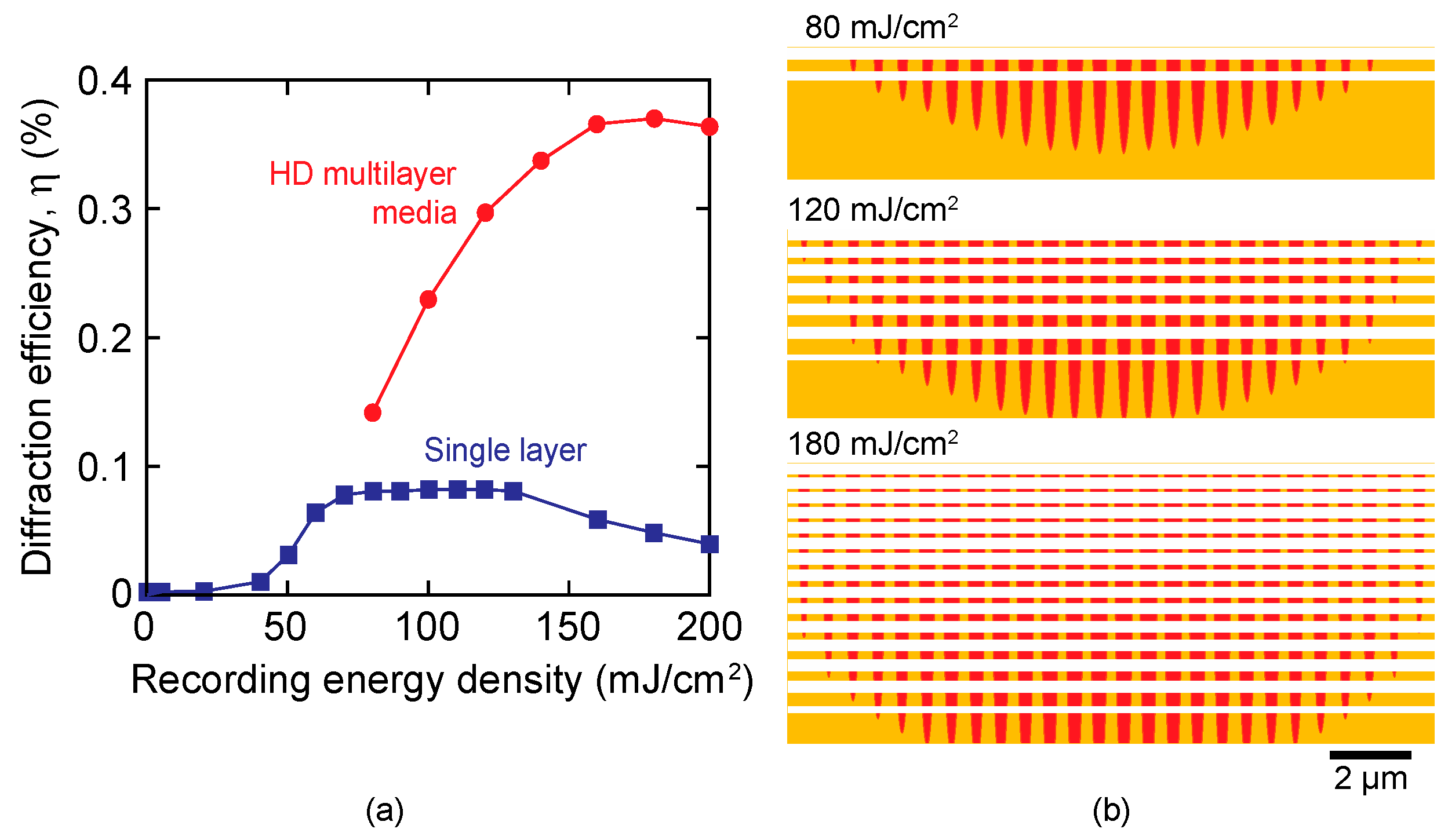
3.2. Effect of Recording Energy

A high recording energy might be effective at forming deep magnetic fringes. Figure 6a illustrates the recording energy dependence of the diffraction efficiency obtained with numerical simulation. As shown in this figure, the diffraction efficiency (black circle symbols) increases with recording energy up to 60 mJ/cm2. However, it reaches saturation, even if the recording energy increases higher than that. To investigate the mechanism in detail, the formation procedure of the magnetic fringe was observed through numerical simulation. The calculated shapes of the magnetic fringe at several recording energies are shown in Figure 6b. As shown in this figure, the total depth of the magnetic fringe increases with the recording energy density; however, the fringe merges near the surface at 81 mJ/cm2 and 102 mJ/cm2. Thus, the effective depth of the fringe is almost the same at approximately 1.6 µm for every case, and this limited effective fringe depth results in the saturation of the diffraction frequency at high recording energies. To investigate the procedure in detail for this merging of adjacent fringes, the time evolution of the temperature distribution in the medium was investigated for the spatial frequency of 1500 line-pairs/mm after laser irradiation, as shown in Figure 6c. The high-temperature region over the Curie temperature surrounded by green lines is separated immediately after laser irradiation; the maximum temperature immediately after laser irradiation reaches approximately 400 °C, and the minimum temperature between the high-temperature region near the surface is still at a room temperature of 25 °C. As the excess heat in the high-temperature region mainly diffuses laterally to the low-temperature region because of the large temperature gradient, the temperature of the low-temperature region rises to a temperature higher than the Curie temperature within 10 ns, as shown in Figure 6c. However, if the shape of the high-temperature region immediately after laser irradiation can be maintained, a high diffraction efficiency can be obtained, as shown in Figure 6a (red square symbols), in which the diffraction efficiency was calculated using a virtual fringe shape identical to the shape of the region heated higher than the Curie temperature immediately after laser irradiation. This strongly suggests that deep and clear magnetic fringes may be recorded if we can suppress the effect of heat diffusion from the regions with excessively high temperatures.

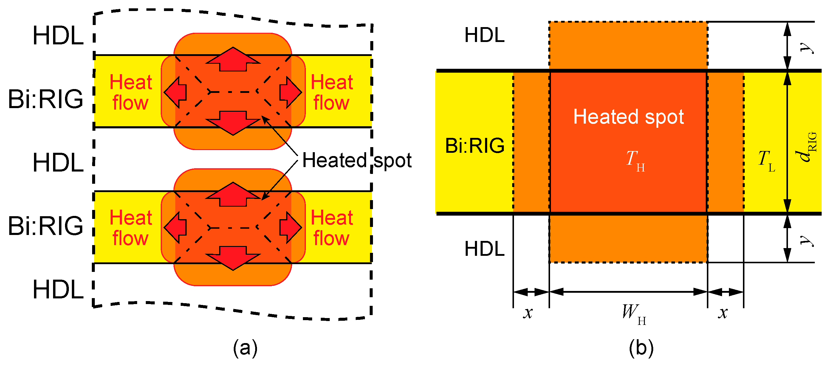
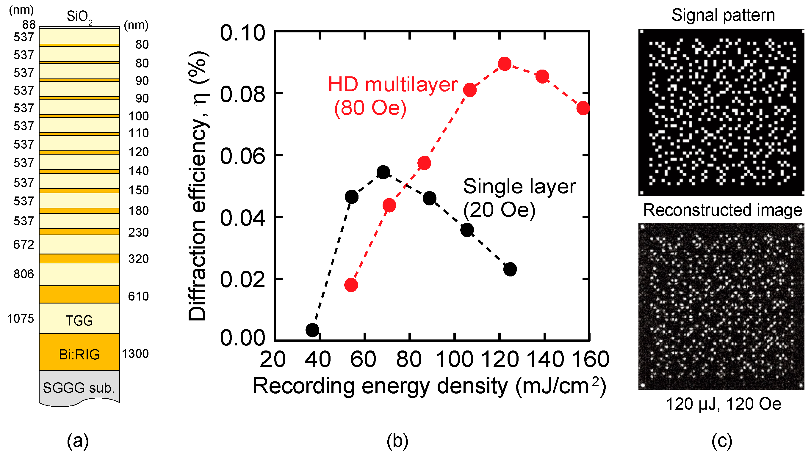
3.3. Design and Properties of HD Multilayer Media

To suppress this heat diffusion effect and control the shapes of the fringes, a stacking structure composed of Bi:RIG and transparent HDLs is effective for diffusing the excess heat from the garnet layers into the HDLs. The fundamental concept of HDLs is shown in Figure 7a. Most of the excess heat at the heated spots caused by the absorption of light energy diffuses to the HDLs, so the amount of heat laterally diffused in the Bi:RIG decreases. Therefore, the temperature increase next to the heated spots in the Bi:RIG decreases, and the increase in the width of the fringes decreases. As a result, the shape of the fringes may be maintained.
For the actual design of HD multilayer media, the thicknesses of the HDLs and garnet layers are important for controlling the heat flow and temperature in the Bi:RIG. A simple model to evaluate their thicknesses shown in Figure 7b is assumed; a Bi:RIG layer with thickness dRIG is sandwiched by HD layers, and the temperature of the heated spot with width WH is set to TH. The heat of this heated spot diffuses to adjacent regions, shown in light orange, and this diffused heat increases the temperature in the adjacent regions within distances x and y in the garnet and HDL. In this process, the temperature of the original heated spot and its adjacent regions shown in orange and light orange in Figure 7b, respectively, is assumed to be a uniform temperature T. In addition, the ratio of the heated length in the garnet and HD layers, x/y, is assumed to be the ratio of the characteristic diffusion length:
x y = k RIG / C RIG k HD / C HD ,
where kRIG and kHD are thermal conductivities of the Bi:RIG and HD layers, and CRIG and CHD are volume heat capacities of the Bi:RIG and HD layers, respectively. In this case, considering the heat balance before and after heat diffusion, we can calculate the size of the region heated up to the Curie temperature, T = TC, as a function of TH and dRIG as follows:
2 x W H = T H T L 2 ( T C T L ) ( 1 + W H d RIG k HS C HS k RIG C RIG ) ,
where TL is the temperature of the nonheated region. Based on Equations (3) and (4), we can determine the appropriate thicknesses of the Bi:RIG and HD layers by determining the acceptable widening of the magnetic fringes 2x/WH for a given TH. In the HDL recording media, because the temperature distribution in the Bi:RIG film differs depending on the thickness to be recorded, it is necessary to design an HD multilayer medium according to the recording thickness.
Figure 8a shows the calculated diffraction efficiency of the HD multilayer media using Al2O3 as the HD material and single-layer medium. The diffraction efficiency of the HD multilayer media increases with the recording energy density up to approximately 150 mJ/cm2, and all HD multilayer media show diffraction efficiencies higher than those in the single-layer medium with the same Bi:RIG thickness. Figure 8b shows the shapes of magnetic fringes in the HD multilayer media recorded at 80, 120, and 180 mJ/cm2. All HD multilayer media maintain the deep and clear magnetic fringes and consequently show high diffraction efficiencies. The magnetic fringe shape recorded at 180 mJ/cm2 indicates that the saturation of the diffraction efficiency is caused by the magnetic fringes reaching the full thickness of the Bi:RIG, and the HDL still functions well at this thickness.
Based on these results, we fabricated the HD multilayer medium shown in Figure 9a in which TGG is used as the HDL material for easy fabrication. In this medium, the uppermost SiO2 layer is used as an antireflective film, and the thicknesses of the TGG layers are sufficiently thicker than that required for HD. The fabricated HD multilayer medium shows a Faraday rotation angle of approximately 2.2 deg/µm, which is slightly smaller than the 2.7 deg/µm of the single-layer medium. Figure 9b shows the diffraction efficiency of the HD multilayer and single-layer media recorded under assist magnetic fields of 80 Oe and 20 Oe, respectively. The maximum diffraction efficiency of the HD multilayer medium is approximately 50% larger than that of the single-layer medium. This suggests that the HDLs effectively absorbed the excess heat and maintained the fringe shape, although the diffraction efficiency of the HD multilayer medium is smaller than the numerically expected efficiency that will reach approximately three times that of the single layer. This small diffraction efficiency is considered to be due to the inhomogeneity in the recording layer and the incomplete magnetization reversal, as described in Section 3.1, even if magnetic assist recording was performed. Because a diffraction efficiency larger than that of the single-layer medium was obtained, 2D data were recorded on this HD multilayer medium using the collinear interference method. The reconstructed image from the HD multilayer medium recorded at 120 µJ under the assist magnetic field of 120 Oe is shown in Figure 9c and is identical to the original signal pattern. This implies that error-free recording and reconstruction were achieved with the HD multilayer medium having discrete magnetic layers in the range of approximately 12 μm. Therefore, the appropriately designed HD multilayer media will be applied to high-diffraction-efficiency magnetic hologram recording media.

4. Conclusions

We investigated in detail the recording process of magnetic holograms in garnet media to achieve high diffraction efficiencies through the formation of deep and clear magnetic holograms. From the analysis of the recording process and recorded hologram, a compositional inhomogeneity was found in the recording garnet, disturbing the formation of a clear hologram. In addition, suppressing the lateral heat diffusion near the surface of the media during the recording process was found to be most important. To achieve this, a simple design method for HD multilayer media was developed, and the HD multilayer medium with transparent HDLs in which the recording magnetic layers are discrete in a film approximately 12-µm thick was designed and fabricated. The diffraction efficiency of the HDL medium was approximately 50% larger than that of the single-layer medium, and error-free reconstruction of 2D page data was also achieved using the HDL medium with the magnetic assist recording technique. This implies that the HDL media can be used as the volumetric magnetic recording medium with high diffraction efficiencies.

Author Contributions

Conceptualization, Y.N. and M.I.; Methodology, Y.N. and M.I.; Validation, Y.N., T.G. and H.U.; Formal Analysis, Y.N. and P.B.L.; Investigation, Y.N.; Writing – Original Draft Preparation, Y.N.; Supervision, M.I.; Funding Acquisition, P.B.L. and M.I.

Funding

This research was funded in part by the Grants-in-Aid for Scientific Research (S) 26220902 and (A) 15H02240.

Acknowledgments

We gratefully acknowledge R. Isogai, N. Sagara, S. Suzuki, K. Kawazu, Z. Shirakashi, and N. Hoshiba for their experimental support, and also greatly appreciate M. Suzuki’s help for the measurement at SPring-8.

Conflicts of Interest

The authors declare no conflict of interest. The funders had no role in the design of the study; in the collection, analyses, or interpretation of data; in the writing of the manuscript, or in the decision to publish the results.

Appendix A

Figure A1a shows a schematic of the calculation model used for the simulation; two Gaussian reference and signal beams with a wavelength of 532 nm were interfered at the surface of the garnet. The calculation was carried out using the following three steps: (i) The interference pattern of the laser beams was determined by electromagnetic calculation, as shown in Figure A1b, and the absorption energy in the garnet film was obtained from the calculated electric field intensity and the absorption coefficient of the garnet. (ii) This calculated absorption energy was used as the heat input in the garnet layer, and the time evolution of the temperature distribution around the garnet was calculated. In this procedure, the garnet film was heated according to the electric field intensity distribution for an irradiation time of 50 ps. During and after heating, the change in temperature distribution was calculated by solving the thermal diffusion equation, as shown in Figure A1c. In this process, the shape of the magnetic fringe in the garnet was determined assuming the magnetization of the regions where the temperature exceeded the Curie temperature of 150 °C, even once, was reversed (Figure A1d). (iii) Finally, only the reference beam irradiated the determined magnetic fringe, as shown in Figure A1e, and the intensities of the transparent and diffracted beams were calculated numerically to determine the diffraction efficiency, where the diffracted light intensity was evaluated as the intensity of the polarized light rotated 90° from the incident light.
Figure A1. (a) Schematic of simulation model, (b) calculated intensity of interfered electric field, (c) temperature distribution around the garnet layer, (d) shape of the formed magnetic fringe (dark gray region), and (e) calculated image of diffracted light where the electric field intensity is shown in the polarized plane rotated 90° from the incident light.
Applsci 09 01738 g0a1

References

  1. Rajchman, J.A. Holographic Optical Memory An Optical Read-Write Mass Memory. Appl. Opt. 1970, 9, 2269–2271. [Google Scholar] [CrossRef]
  2. Mikaeliane, A.L.; Bobrinev, V.I. Holographic Memory Devices. Opto-Electronics 1970, 2, 193–199. [Google Scholar] [CrossRef]
  3. Sakaguchi, M.; Nishida, N.; Nemoto, T. A New Associative Memory System Utilizing Holography. IEEE Trans. Comput. 1970, 19, 1174–1181. [Google Scholar] [CrossRef]
  4. Takeda, Y. Hologram Memory with High Quality and High Information Storage Density -Hologram Memory-. Jpn. J. Appl. Phys. 1972, 11, 656–665. [Google Scholar] [CrossRef]
  5. D’Auria, L.; Huignard, J.P.; Spitz, E. Holographic read-write memory and capacity enhancement by 3-D storage. IEEE Trans. Magn. 1973, 9, 83–94. [Google Scholar] [CrossRef]
  6. Curtis, K.; Pu, A.; Psaltis, D. Method for holographic storage using peristrophic multiplexing. Opt. Lett. 1994, 19, 993–994. [Google Scholar] [CrossRef]
  7. Hong, J.H.; McMichael, I.C.; Chang, T.Y.; Christian, W.R.; Paek, E.G. Volume holographic memory systems: techniques and architectures. Opt. Eng. 1995, 34, 2193–2203. [Google Scholar] [CrossRef]
  8. Breuckmann, B.; Thieme, W. Computer-aided analysis of holographic interferograms using the phase-shift method. Appl. Opt. 1985, 24, 2145–2149. [Google Scholar] [CrossRef] [PubMed]
  9. Rakuljic, G.A.; Leyva, V.; Yariv, A. Optical data storage by using orthogonal wavelength-multiplexed volume holograms. Opt. Lett. 1992, 17, 1471–1473. [Google Scholar] [CrossRef] [PubMed]
  10. Li, H.-Y.S.; Psaltis, D. Three-dimensional holographic disks. Appl. Opt. 1994, 33, 3764–3774. [Google Scholar] [CrossRef] [PubMed]
  11. Psaltis, D.; Levene, M.; Pu, A.; Barbastathis, G.; Curtis, K. Holographic storage using shift multiplexing. Opt. Lett. 1995, 20, 782–784. [Google Scholar] [CrossRef]
  12. Horimai, H.; Tan, X.; Li, J. Collinear holography. Appl. Opt. 2005, 44, 2575–2579. [Google Scholar] [CrossRef]
  13. Horimai, H.; Tan, X. Advanced collinear holography. Opt. Rev. 2005, 12, 90–92. [Google Scholar] [CrossRef]
  14. Horimai, H.; Tan, X. Holographic information storage system: today and future. IEEE Trans. Magn. 2007, 43, 943–947. [Google Scholar] [CrossRef]
  15. Mezrich, R.S. Curie-point writing of magnetic holograms on MnBi. Appl. Phys. Lett. 1969, 14, 132–134. [Google Scholar] [CrossRef]
  16. Mezrich, R.S. Reconstruction effects in magnetic holography. IEEE Trans. Magn. 1970, 6, 537–541. [Google Scholar] [CrossRef]
  17. Mezrich, R.S. Magnetic holography. Appl. Opt. 1970, 9, 2275–2279. [Google Scholar] [CrossRef] [PubMed]
  18. Haskal, H.M. Polarization and efficiency in magnetic holography. IEEE Trans. Magn. 1970, 6, 542–545. [Google Scholar] [CrossRef]
  19. Nakamura, Y.; Takagi, H.; Lim, P.B.; Inoue, M. Effect of recording condition on the diffraction efficiency of magnetic hologram with magnetic garnet films. J. Appl. Phys. 2014, 116, 103106. [Google Scholar] [CrossRef]
  20. Tanaka, M.; Ito, T.; Nishimura, Y. Diffraction efficiency of magnetic hologram. IEEE Trans. Magn. 1972, 8, 523–525. [Google Scholar] [CrossRef]
  21. Nakamura, Y.; Takagi, H.; Lim, P.B.; Inoue, M. Magnetic volumetric hologram memory with magnetic garnet. Opt. Express 2014, 22, 16439–16444. [Google Scholar] [CrossRef]
  22. Isogai, R.; Sagara, N.; Goto, T.; Nakamura, Y.; Lim, P.B.; Inoue, M. Diffraction efficiency of volumetric magnetic holograms with magnetophotonic crystals. J. Magn. Soc. Jpn. 2014, 38, 119–122. [Google Scholar] [CrossRef]
  23. Isogai, R.; Goto, T.; Takagi, H.; Nakamura, Y.; Lim, P.B.; Inoue, M. Effect of structure and properties of magnetic material on diffraction efficiency of magnetophotonic crystal media for magnetic volumetric holography. J. Magn. Soc. Jpn. 2015, 39, 33–36. [Google Scholar] [CrossRef]
  24. Isogai, R.; Suzuki, S.; Nakamura, K.; Nakamura, Y.; Takagi, H.; Goto, T.; Lim, P.B.; Inoue, M. Collinear volumetric magnetic holography with magnetophotonic microcavities. Opt. Express 2015, 23, 13153–13158. [Google Scholar] [CrossRef]
  25. Isogai, R.; Nakamura, Y.; Takagi, H.; Goto, T.; Lim, P.B.; Inoue, M. Thermomagnetic writing into magnetophotonic microcavities controlling thermal diffusion for volumetric magnetic holography. Opt. Express 2016, 24, 522–527. [Google Scholar] [CrossRef] [PubMed]
  26. Nakamura, Y.; Shirakashi, Z.; Takagi, H.; Lim, P.B.; Goto, T.; Uchida, H.; Inoue, M. Error-free reconstruction of magnetic hologram via improvement of recording conditions in collinear optical system. Opt. Express 2017, 25, 15349–15357. [Google Scholar] [CrossRef]
  27. Shirakashi, Z.; Goto, T.; Takagi, H.; Nakamura, Y.; Lim, P.B.; Uchida, H.; Inoue, M. Reconstruction of non-error magnetic hologram data by magnetic assist recording. Sci. Rep. 2017, 7, 12835. [Google Scholar] [CrossRef] [PubMed]
  28. Mito, S.; Sakurai, H.; Takagi, H.; Baryshev, A.V.; Inoue, M. Polycrystalline magnetic garnet films comprising weakly coupled crystallites for piezoelectrically-driven magneto-optic spatial light modulators. J. Appl. Phys. 2012, 111, 07A519. [Google Scholar] [CrossRef]
Figure 1. Thermomagnetic recording process of magnetic hologram. (a) Unidirectionally magnetized film; (b) partial heat-up due to the absorption of laser energy; (c) disappearance of the magnetization of regions heated higher than the Curie temperature; (d) reversal of the magnetization of such regions due to the stray magnetic field.
Applsci 09 01738 g001
Figure 2. Experimental setup for two-beam and collinear interference systems [27]. In the collinear system, both reference and signal parts shown on the digital micromirror device are irradiated on the recording medium for recording, and only the reference parts are irradiated for reconstructing the hologram. In the two-beam interference system, a laser beam is divided into two by a half mirror and incident on the medium for recording, and one of the beams is stopped by a shutter for reconstruction.
Applsci 09 01738 g002
Figure 3. Cross sectional view of a typical garnet film that consists of grains with size 20–55 nm. Because the grain size is approximately 50 nm or less, interference fringes with 1500 line-pairs/mm (667 nm periods) are recorded with 13 or more grains. Adapted with permission from Reference [21].
Applsci 09 01738 g003
Figure 4. Diffraction efficiency of the magnetic hologram normalized to that at 500 line-pairs/mm: Comparison between simulation and experimental results at various spatial frequencies. In both experiments and simulations, the diffraction efficiencies decreased on increasing the spatial frequency of the interference fringes.
Applsci 09 01738 g004
Figure 5. XMCD mapping images of magnetic interference fringes recorded at spatial frequencies of (a) 500 and (b) 1500 line-pairs/mm, and (c) Fe intensity at the same location as that for 500 line-pairs/mm. In the case of 500 line-pairs/mm, contrast changes at 2-μm intervals are observed in the XMCD image, while the stripes of the XMCD tend to be disturbed in the dark regions of the Fe intensity distribution shown in (c). On the other hand, the contrast changes at 0.7-µm intervals are less clear in the case of 1500 line-pairs/mm.
Applsci 09 01738 g005
Figure 6. (a) Calculated diffraction efficiency at 1500 line-pairs/mm. The usual diffraction efficiency (black circles) is saturated at energy densities higher than 60 mJ/cm2, while continuously increasing, when the virtual fringes immediately after laser irradiation are used (red squares). (b) Shapes of magnetic fringes recorded at various energy densities. (c) Variation in temperature distribution after laser irradiation recorded at 81 mJ/cm2. The shape of the regions with a temperature higher than the Curie temperature (150 °C) is surrounded by green lines.
Applsci 09 01738 g006
Figure 7. (a) Fundamental concept of HDLs. Most of the excess heat at the heated spots diffuses to the HDLs, so the amount of heat laterally diffused in the Bi:RIG decreases and the increase in temperature of the Bi:RIG is also reduced. (b) Model for design of thicknesses of garnet and HDL.
Applsci 09 01738 g007
Figure 8. (a) Calculated diffraction efficiency of HD multilayer and single-layer media. (b) Calculated shapes of magnetic fringes in HD multilayer media for energy densities of 80 mJ/cm2, 120 mJ/cm2, and 180 mJ/cm2.
Applsci 09 01738 g008
Figure 9. (a) Designed structure of HD multilayer medium; (b) diffraction efficiency of HD multilayer and single-layer media; (c) signal pattern and reconstructed image from HD multilayer medium recorded at 120 µJ under an assist magnetic field of 120 Oe using collinear interferometer. There is no pixel error between them, and error-free reconstruction was achieved.
Applsci 09 01738 g009

