1. Introduction
The modular multilevel converter (MMC), a new type of voltage source converter (VSC), has many advantages over the traditional two or three level topology, such as better harmonic performance, low switching frequency, etc. This advanced technology is envisioned as the most promising option for the integration of renewable energy sources and has been widely investigated in recent years [
1,
2,
3]. In China, an MMC-HVDC grid usually uses overhead lines because large-scale renewable energy bases are generally far from load centers, as it makes the fault ride-through of MMC-HVDC grid become more thorny [
4].
Currently, the half-bridge sub-module (HBSM) is the main topology of a practical MMC-HVDC grid because of better economy [
5]. When a short-circuit fault occurs on the DC line, very large fault currents will be caused in the DC lines and converters [
6]. Since temporary faults often occur on overhead lines, MMC-HVDC needs reclosing to improve the reliability and continuity of the power supply [
7]. Consequently, the vulnerable power electronic elements in the converter will be exposed to overcurrent again when the system attempts to reclose a permanent fault.
The suppression of overcurrent mainly depends on an effective fault current limiter (FCL). Reference [
8] limited the overcurrent in HVDC lines by a current limiting inductor (CLI) and studied the impact of different sizes on current rise. Reference [
9,
10] studied the performance of a superconducting fault current limiter (SFCL) and concluded that the appropriated SFCL can reduce the fault current peak, the size of the CLI and also the fault identification time. Reference [
11] presented a solid state FCL in a VSC-HVDC system with MMC converters, but the detailed structure and the configuration method were not clear. Reference [
12,
13] both proposed a resistive DC fault current limiter. The limiter was installed in each arm or at the outlet of the converter to increase the damping performance of the DC fault current loop and effectively limit the dc-side current, and then interrupt the fault circuit by a breaker. Reference [
14] proposed a RL-FCL which is composed of a reactor, a resistor, a reversed diode and an IGBT connected in parallel to limit the overcurrent and the overvoltage. The aforementioned references mainly focused on the overcurrent limiting when the fault occurred but did not conduct further research on the post-fault and the reclosing process.
There has been little research on reclosing process, especially for MMC-HVDC. Reference [
15] used two thyristors in parallel with the sub-modules to realize fault clearance and automatic recovery, but the converter must be blocked for a long time when reclosing a permanent fault. Reference [
16] used series braking resistance (SBR) cooperating with a high-temperature superconducting FCL to reduce the fault currents during reclosing, but it did not illustrate how to select the parameter of the SBR. A soft reclosing model (SRM) is proposed in Reference [
17] to limit the reclosing over-current of VSC-MTDC. However, the current calculation in this reference is made on the assumption that the voltage discharge voltage remains constant and neglects the restriction of the safety of the equipment. Overcurrent suppression during the reclosing process of MMC-HVDC needs further research.
This paper focuses on the suppression of overcurrent for overhead lines based MMC-HVDC grid during the reclosing process. First, mesh current method (MCM) based short-circuit current calculation is introduced to a loop MMC-HVDC grid. Then a novel FCL, which consists of a CLI, a reclosing current limiting resistance (RCLR) and a bypass switch, is proposed. Compared with traditional FCL, the proposed circuit can limit the maximum arm currents to a specified value during the reclosing process, and the calculation method of RCLR is also given in details.
2. Fault Current Calculation of a Loop MMC-HVDC Grid
2.1. Characteristics of a Pole-to-Pole Fault
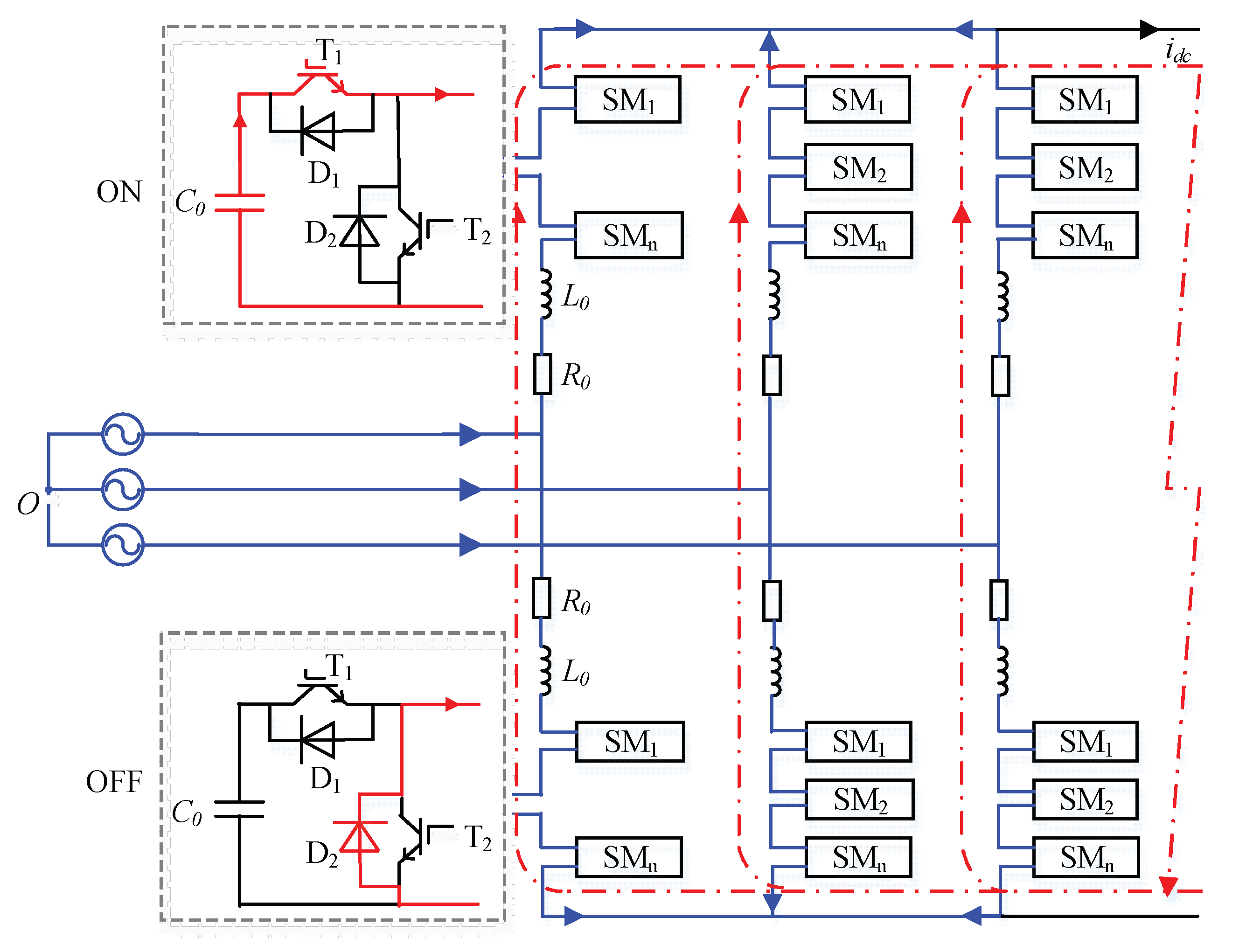
A common three-phase MMC is shown in
Figure 1. It is composed of six arms and each arm consists of N sub-modules (SMs) connected in series and an arm inductor L
0. Each SM includes two insulated gate bipolar transistors (IGBTs), two diodes and a DC capacitor C
0. If the SM is ‘ON’ state, the output of SM is the dc capacitor voltage. When the SM is ‘OFF’ state, the output of SM is zero.
The pole-to-pole fault is the most serious fault in the DC side of MMC-HVDC. The fault process can be divided into two stages according to whether the converter is blocked [
18].
Before the converter is blocked, the arm current is shown in
Figure 1. During this stage, all the capacitors of SMs in ‘ON’ state will discharge through T
1 immediately (the red line), and thus the currents in the arms and DC lines increase extremely fast. For the AC system, the fault is equivalent to a three-phase short-circuit. So, the AC system also injects short-circuit currents (the blue line) during this stage, whereas they are not capable of flowing into the DC lines, because their contributions sum to zero in the converter. The arm current is a superposition of the discharging current and three-phase short-circuit current. Due to the sorting algorithm within the converter, there are always N SMs being switched in thus all the SMs will discharge during the fault. Given to the high control frequency, the SMs in the upper and the lower arm can be regarded as discharging at the same time. Therefore, the equivalent circuit of the converter during this stage is displayed as
Figure 2.
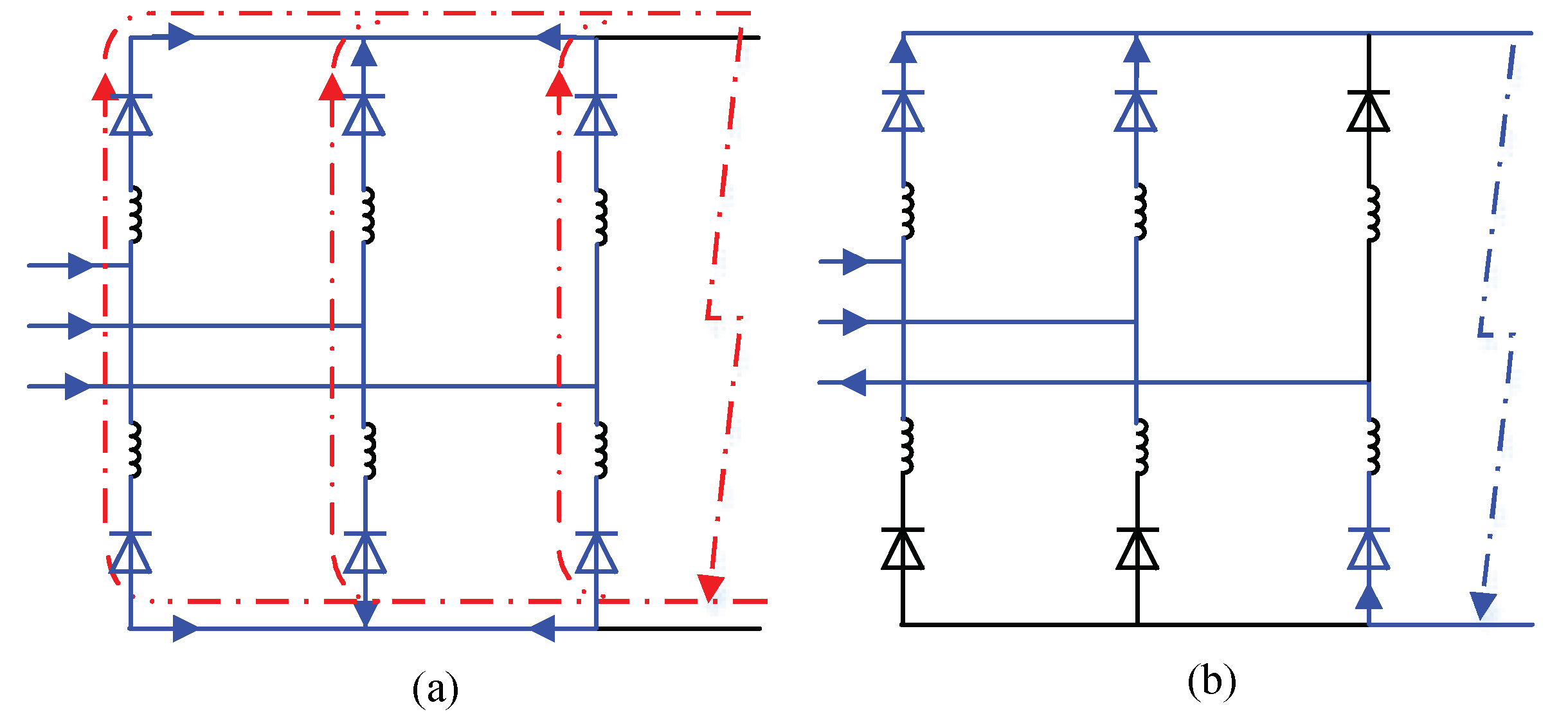
If the arm current in any arm exceeds the threshold of overcurrent protection of SM, the converter will be blocked immediately. The fault process after blocking can be further divided into two sub-stages. The first one is inductor free-wheeling circuit as is shown in
Figure 3a. The fault currents are maintained by the arm inductor. At this stage, each arm still carries a third of the DC line current, and no AC currents are injected in DC line.
The stage of inductor free-wheeling will end when the inductor free-wheeling current decrease to zero. Then the converter starts to act as an uncontrolled rectifier as
Figure 3b. At this stage, the fault currents in the DC lines are fed by the AC system. Generally, the protection time in MMC-HVDC grid is within 5 ms after the fault occurrence [
19], so this stage of the uncontrolled rectifier seldom occurs in practical system.
2.2. Short-Circuit Current Calculation Method
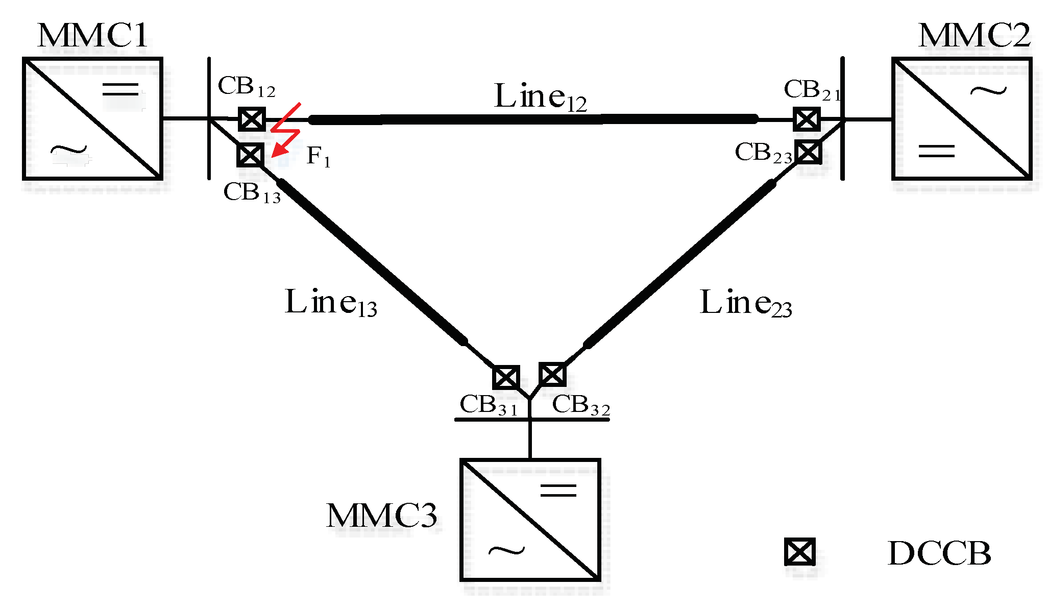
The short-circuit current calculation of a loop MMC-HVDC is different from that of a two-terminal MMC-HVDC or a star join multi terminal DC grid as the fault current of the latter can be calculated separately. For a loop MMC-HVDC, as displayed in
Figure 4, all the converters inject fault current through different lines to the fault spot, and the currents from different converters cause coupling problem.
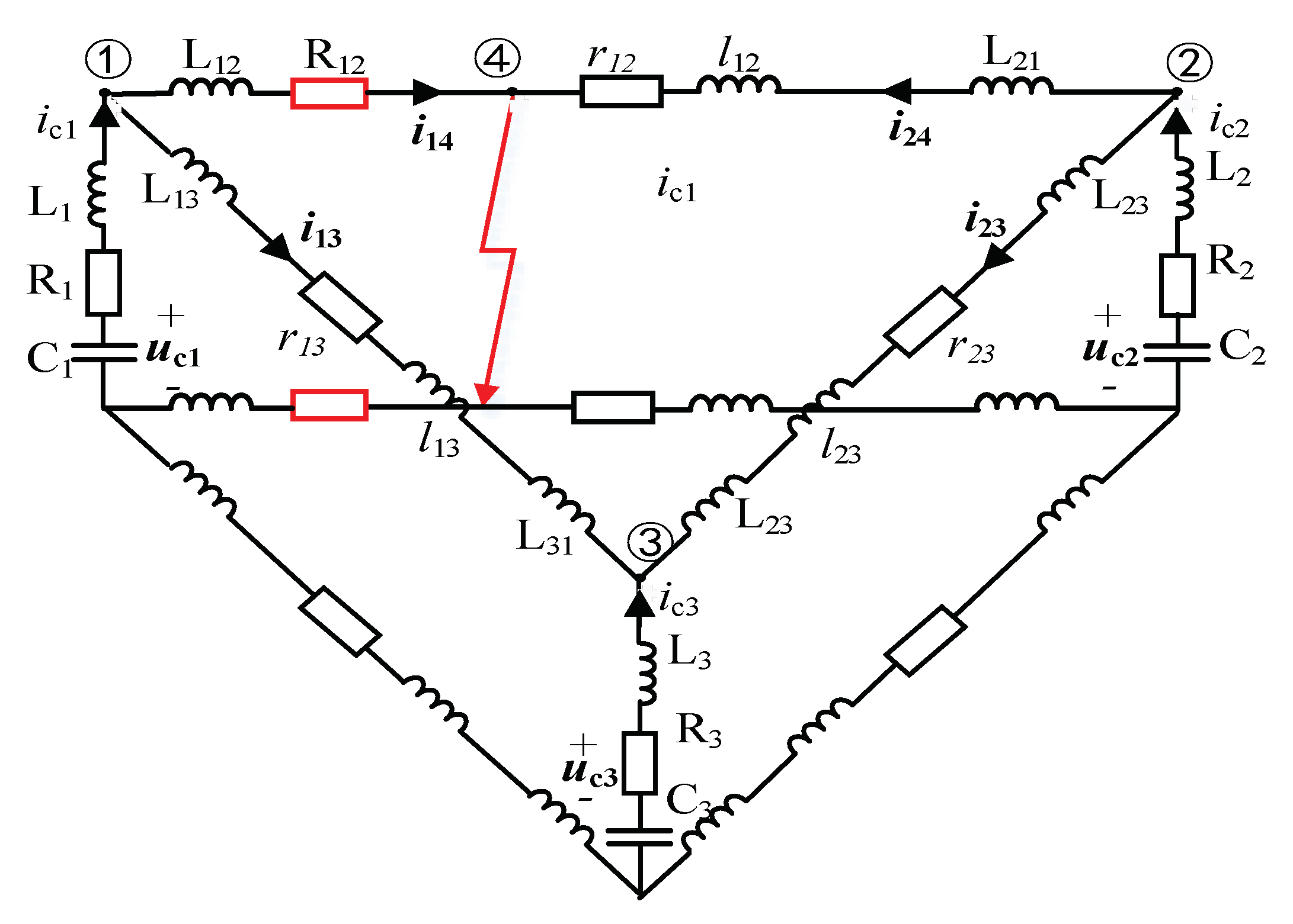
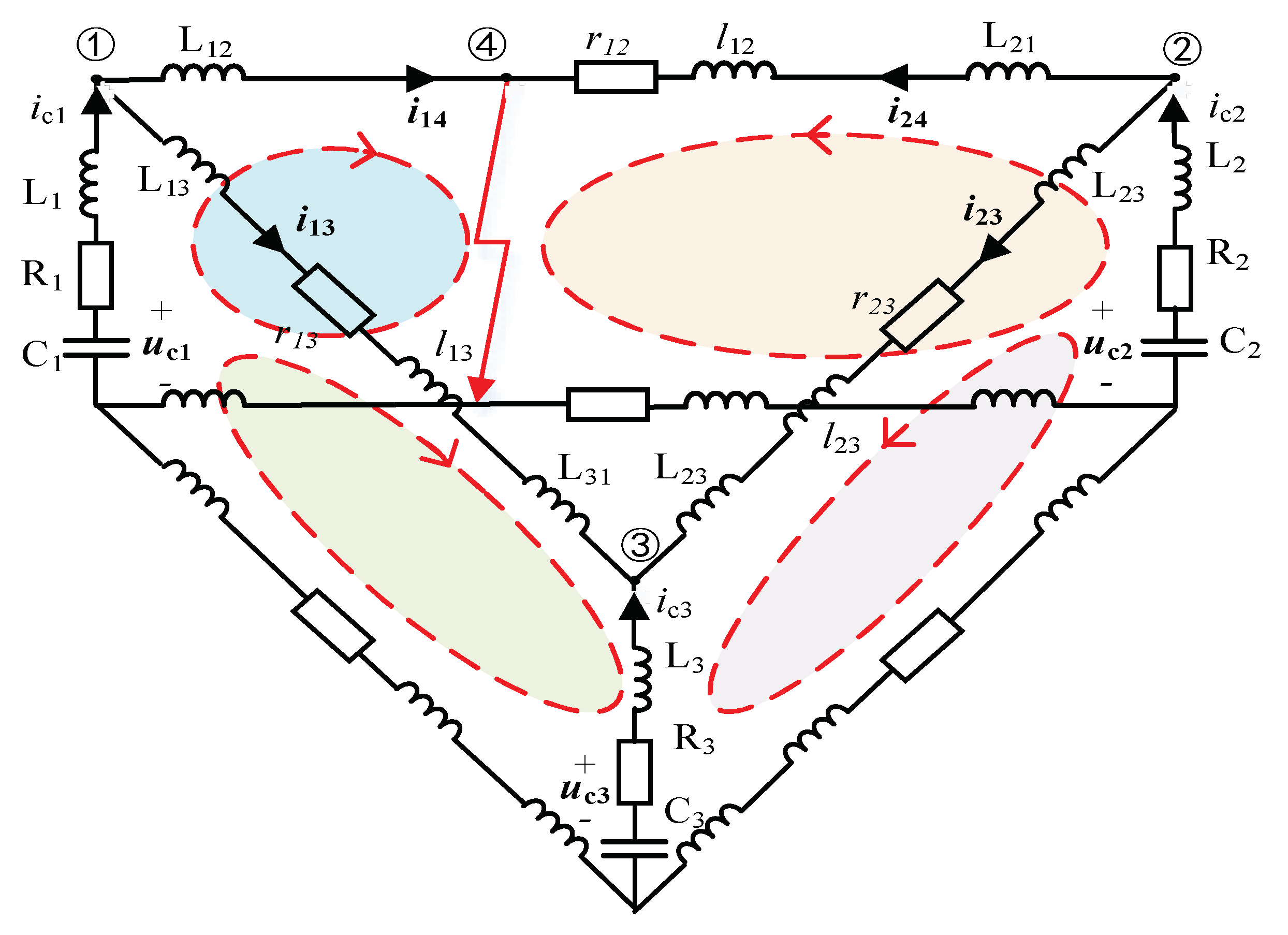
To handle the current coupling problem, the mesh current method (MCM) is first introduced to a short-circuit current calculation of MMC-HVDC grid before the converters are blocking. For example, when there is a pole-to-pole fault at the DC outlet of MMC1, the whole grid can be divided into four meshes. The equivalent circuit is illustrated in
Figure 5. L
i, C
i and R
i represent the equivalent circuit of the converter,
rij and
lij represent the DC overhead lines and L
ij is CLI. According to the four meshes, a state equation can be established as Equations (1) and (2). Then the current in different lines can be calculated.
3. Operation Principle of the Reclosing Current Limiting Resistance based Fault Current Limiter
3.1. The Operation Principle of the Fault Current Limiter
The CLI is an effective and mature device to limit fault currents in the MMC-HVDC grid, but it can’t further reduce the overcurrent stresses on the power electronic elements in the converter in the reclosing process. Therefore, an additional circuit, which is composed of an RCLR and a parallel switch, is proposed based on the traditional CLI, as shown in the dotted line box of
Figure 6.
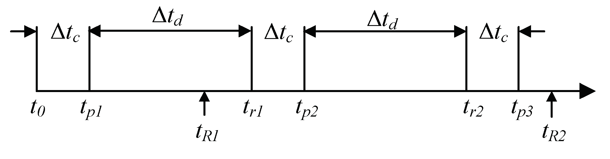
Similar to an AC system, the fault ride-through of an overhead lines based MMC-HVDC grid needs two or three reclosing attempts to determine whether the fault is temporary.
Figure 7 shows the sequence of fault ride-through when reclosing a permanent fault. The fault starts at the instant of
t0, and the DCCB on the faulty line will be tripped at
tr1 after the protection identification time of Δ
tc. During the deionization time of Δ
td, the bypass switch is opened, and thus the RCLR is inserted into the fault loop. The DCCB is reclosed at
tp1 and tripped again at
tr2 after detecting there is still a fault. By using the RCLR, the overcurrent stresses on powering electronic elements can be reduced significantly, and the converter can keep continuous operation. The same reclosing process will be done at
tp2 and
tr2. At last, the DCCB will never be reclosed after the identification of a permanent fault. The bypass switch is opened at
tR2 and waits for the next operation command.
3.2. The Calculation Method of RCLR
There are two main electric elements in the proposed FCL. The main function of CLI is to limit the rise rate of fault currents and ensure the reliable operation of the DCCB, while that of the RCLR is to reduce the overcurrent in the converter during reclosing. Extensive papers have studied the calculation method of the CLI in MMC-HVDC grid [
8,
20,
21,
22], so it will not be discussed in this paper. The main contribution of this paper is to propose a novel calculation method of RCLR, which can limit the arm currents to a specified value. According to the aforementioned analysis, the constraint of the RCLR is denoted by Equation (3).
Imax represents the maximum value of arm current during reclosing,
Ith represents the threshold of SMs overcurrent protection, and
k is ratio coefficient which denotes the limiting level of fault currents.
By using the RCLR, only SMs discharging will appear during reclosing, whereas it is difficult to describe the accurate relations between arm currents and RCLR through mathematical equations. In order to solve this problem, a method of estimating the maximum arm current is proposed. The FCL reduces the discharging speed of the SMs significantly during reclosing, so the AC output can be considered still under control within the several milliseconds after fault. If the circulating currents in the arm are neglected, the maximum current in the arm is approximately equal to Equation (4)
where
iac is the amplitude of phase current in the AC side of converter,
idc represents the current measured at positive pole of the converter shown in
Figure 1, and the Δ
tc is protection time from reclosing time to the trip time of the DCCB. By substituting (4) into (3), the following inequality can be obtained as Equation (5). Define the value satisfying the equation condition of (5) as the critical resistance R
0.
4. Simulation
4.1. The Test System
A three-terminal MMC-HVDC grid, shown in
Figure 4, is modeled based on PSCAD/EMTDC simulation platform. The system adopts the symmetric monopole configuration with a rated DC voltage of ±20 kV. All the converters are connected by bipolar transmission lines which make use of a frequency-dependent distributed parameter model, and a hybrid DCCB and a FCL are placed at the terminal of each line. MMC1 and MMC3 control the active power, while MMC2 controls the DC voltage. The detailed parameters of the test system are shown in
Table 1. Other simulation parameters are set as follows: the protection time Δ
tc is 5 ms; the deionization time Δ
td is 150 ms; the threshold of SMs overcurrent protection
Ith is 2 kA; the CLI on each line is 15 mH. Moreover, the converter will be blocked after the fault current declines to 10 A.
4.2. The Validation of the FCL
For the test system, a pole-to-pole fault F
1 is applied at the DC outlet of MMC1. The overcurrent in MMC1 is the most serious, and thus it will be taken as the example for simulation. When the RCLR R
12 is configured, the equivalent circuit in
Figure 4 is modified as
Figure 8 and Equation (1) is modified as Equation (6). The upper and lower limitation of the RCLR are set to 0 and 15 Ω, respectively, and the calculation step is 0.1 Ω.
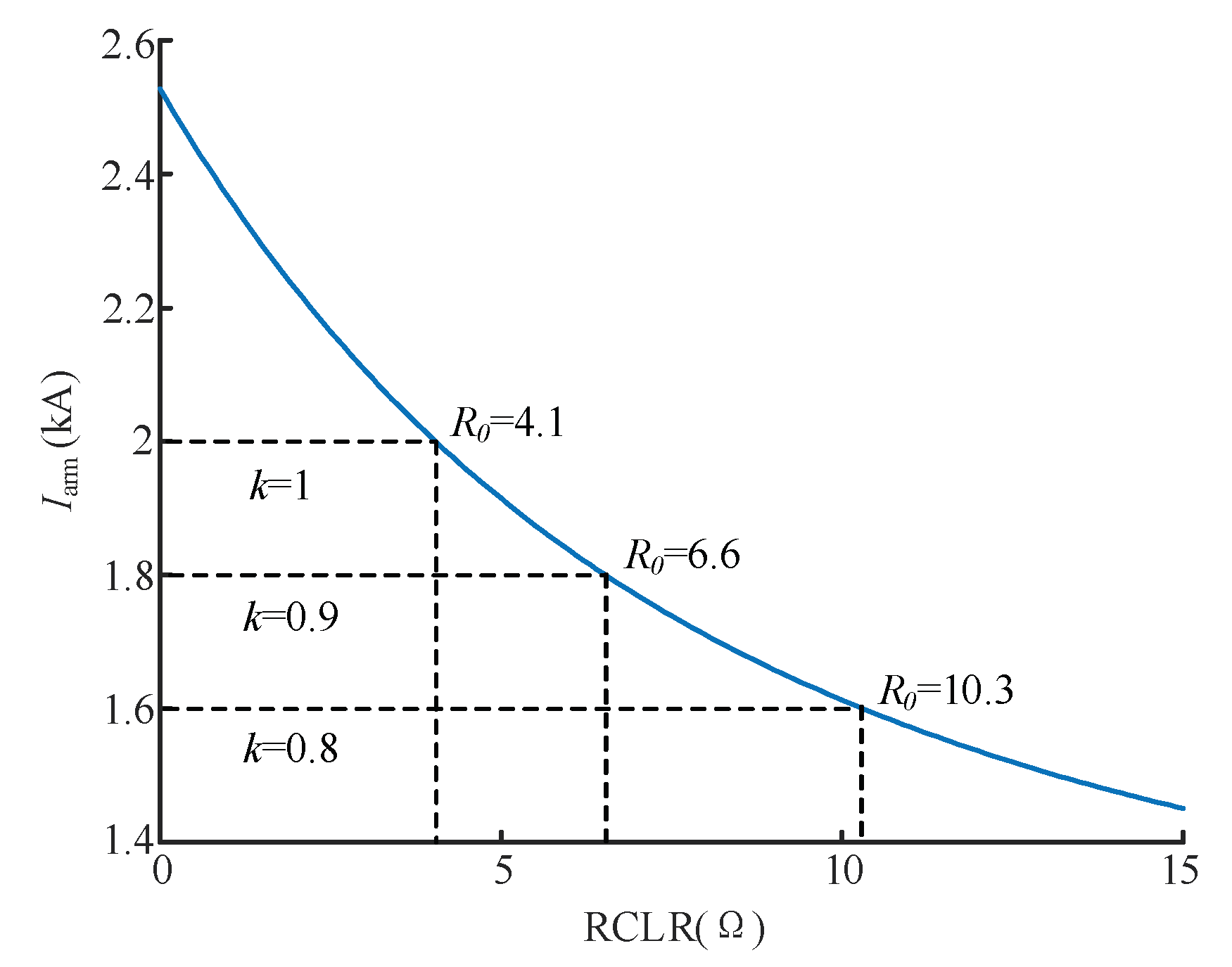
By solving (2) and (6), the relation between the maximum arm current and the critical resistance R
0 of FCL can be obtained, as shown in
Figure 9.
Take
k = 1,
k = 0.9 and
k = 0.8 for examples to verify the effectiveness of the proposed calculation method.
Figure 10 shows the DC currents on the faulty line where ‘k = ×’ means without RCLR (only using the CLI).
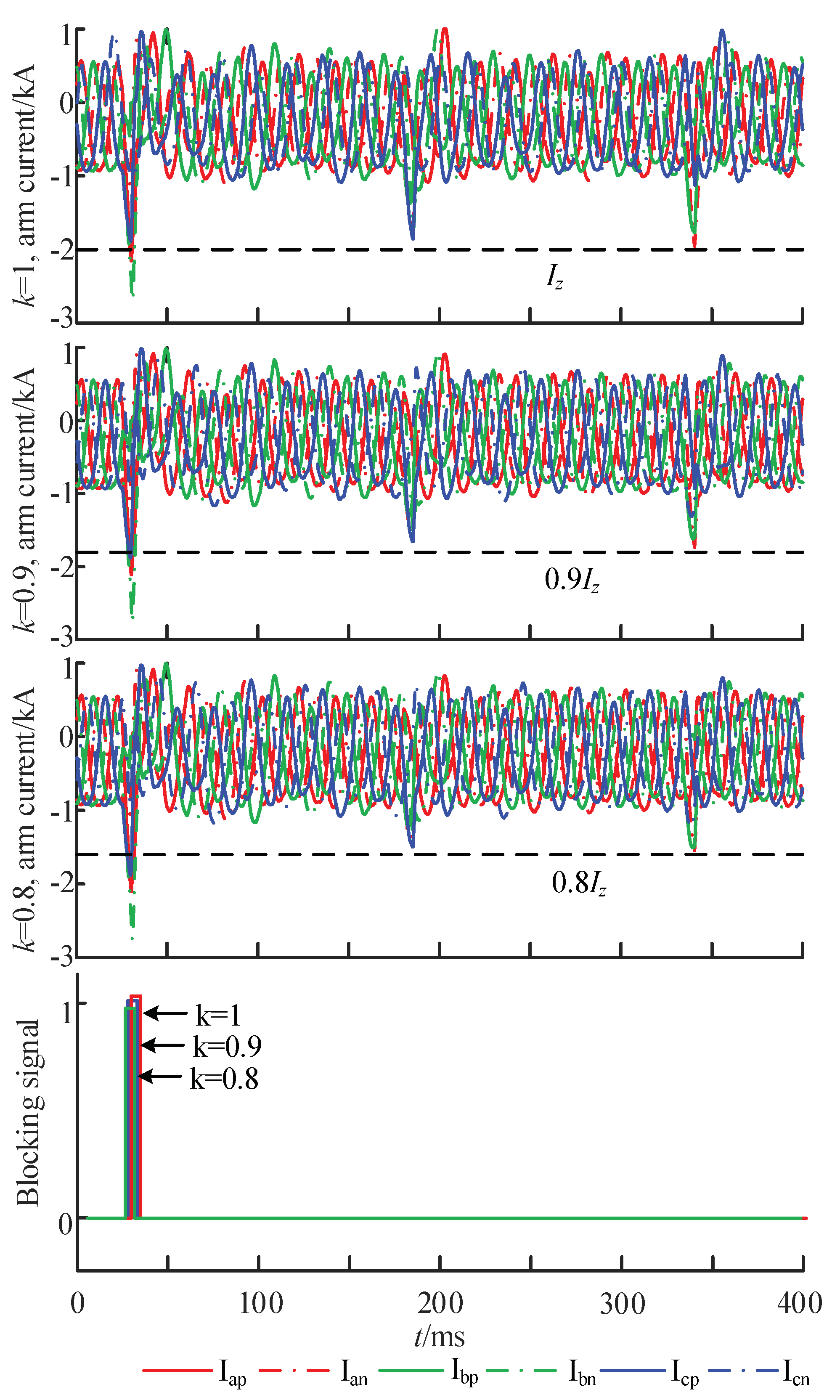
Figure 11 shows the arm currents in MMC1 under different current limiting levels.
As is observed in
Figure 10 and
Figure 11, serious overcurrent still exists without RCLR during reclosing, and the converter is blocked again when reclosing the DCCB leading to the interruption of power flow for a long time. However, by using the proposed RCLR, the fault currents in both the faulty line and converter will be reduced significantly during reclosing, and the converter can keep continuous operation without blocking. As it is observed in
Figure 12, the maximum value of arm current under different current limiting level is close to but less than the specified value and the converters are not blocked during the reclosing process. The proposed method can meet the overcurrent limiting requirement with a lower resistance value proving the calculation method is accurate and effective.
5. Discussion
There has been wide research on the fault current limiter (FCL), such as the current limiting inductor (CLI), superconducting fault current limiter (SFCL), Solid State FCL and resistive fault current limiter. All the limiters will work when the fault occurs to limit the current to a lower amplitude and then break the fault circuit. For CLI, it is capable of limiting the overcurrent rise, but too many inductors in the DC grid will influence the transient response, stability and the speed for DCCB interrupting the fault current. Moreover, a large value inductor will bring large size and manufacturing burdens. For SFCL, it can reduce the fault current peak and the size of CLI, but it costs too much. A solid state FCL can interrupt the DC fault current very quickly in even hundreds of microseconds but the extra large amount of power electronic components bring much conduction loss. Resistive fault current limiter usually aims to accelerate the process of fault current decaying and is often activated by electronic switches but neglects the high voltage exerted on the electronic components at the switching. The above current limiting strategies all mean to limit the current to some level making the DCCB or other breakers to interrupt the fault current more quickly and easily. None of them pay attention to the post-fault process.
Research on the current limiting during the reclosing process for MMC-HVDC is really rare. Reclosing is necessary for an MMC-HVDC system to determine whether the fault is temporary or permanent. For a permanent pole-to-pole fault, the arm will undergo overcurrent again during each reclosing process. So, the overcurrent suppression during the reclosing process is of great significance. In the present literature, resistive limiters have been proposed but there are two problems remaining unsolved. Firstly, none of them accurately calculated the overcurrent, which is the base of current limiting. Secondly, a detailed configuration method of the limiter, especially of the calculation of the resistor, was not given or well-thought-out. In this paper, accurate current is calculated based on the proposed mesh current method, and the detailed calculation method of RCLR is conducted. The selection of resistor is based on different limiting levels of the fault current which is flexible for different thresholds of SMs overcurrent protection. The proposed method in this paper can limit the overcurrent to a required level with a lower resistance value.
6. Conclusions
Overcurrent will recur during the reclosing process without any current limiting strategy under a permanent pole-to-pole fault in MMC-HVDC which may threaten the safety of the power electronic elements and even the system. Moreover, the overcurrent will make the converter block repeatedly. To configure a reasonable FCL, the key is to calculate the overcurrent accurately and figure out the tolerance for the overcurrent. In this paper, a mesh current method (MCM) is proposed to calculated the short-circuit current based on the state equation. Based on the current calculation and the threshold of SMs overcurrent protection, the configuration principle of the reclosing current limiting resistance is proposed. The simulations constructed in PSCAD/EMTDC prove that the proposed method in this paper can limit the overcurrent in the arm to a required level under different limiting levels to protect the power electronic elements and preventing the converter frequently blocking during the reclosing process which may shorten the recovery time for the system. So, the overcurrent suppression strategy during the reclosing process of MMC-HVDC proposed in this paper is effective from the perspective of security and operation efficiency.


