Article

Coupled Analysis of Offshore Wind Turbine Jacket Structures with Pile-Soil-Structure Interaction Using FAST v8 and X-SEA

1
Konkuk University, 120 Neungdong-ro, Gwangjin-gu, Seoul 05029, Korea
2
MaREI Centre for Marine and Renewable Energy, University College Cork, Cork P43C573, Ireland
*
Author to whom correspondence should be addressed.
Appl. Sci. 2019, 9(8), 1633; https://doi.org/10.3390/app9081633
Submission received: 21 February 2019 / Revised: 2 April 2019 / Accepted: 8 April 2019 / Published: 19 April 2019
(This article belongs to the Special Issue Offshore Wind Energy)

Abstract

:
The coupled analysis between a turbine in operating condition and a complex jacket support structure was formulated in this paper for the reliable evaluation of offshore wind turbine structures including pile-soil-structure interactions (PSSIs). Discussions on the theoretical and simulation aspects of the coupled analysis are presented. The dynamic coupled analysis was implemented in X-SEA program and validated with FAST v8 (fatigue, aerodynamics, structures and turbulence) developed by NREL, USA. By replacing the sub-structural module in the FAST with the component of offshore substructure in the X-SEA, the reaction forces and the turbine loads were calculated in each time step and the results from X-SEA were compared with that from FAST. It showed very good agreement with each other. A case study of a NREL 5MW offshore wind turbine on a jacket support structure was performed. Coupled dynamic analyses of offshore wind turbine and support structures with PSSI were carried out. The results showed that in the coupled analysis, the responses of the structure are significantly less than in the uncoupled analysis. The support structure considering PSSI exhibited decreased natural frequencies and more flexible responses compared to the fixed-support structure. The implemented coupled analysis including PSSI was shown to be more accurate and computationally efficient.

1. Introduction

In order to construct an offshore wind turbine (OWT), an engineer should select a proper support structure concept. The selection depends on various factors including water depth, environmental and seabed conditions, and installation equipment where water depth and seabed conditions are two basic factors. A few common types of offshore wind support structures include monopile, gravity, tripod, jacket and floating types [1]. Monopile (as shown in Figure 1a) and gravity structures are often found to be the most suitable for shallow water regions, where the water depth is lower than 30 m. Tripod and jacket structures, as respectively shown in Figure 1b,c, can be built in transitional water regions, which have a water depth between 30 and 50 m [1]. Floating types are expected to be the most cost-effective and reasonable solution for deeper waters [2]. While the monopile transfers the lateral and moment loads by bending to the soil, both the tripod and jacket dissolve the global moments to pairs of forces and transfer them as axial loads to the soil, and are advantageous especially in weak soils [3]. They are considered to be a relatively lightweight concept and have good stability and overall stiffness [4]. Compared to the tripod concept, the jacket foundation concept is more preferable in terms of scour, ship collision, complexity of joints, deflection at tower top and overall weight [3]. The study in this paper focuses on jacket-foundation supported OWTs.
The jacket foundation concept consists of three parts: Piles, jackets and transition pieces. The jacket is characterized by three or four legs. It appears that the four-legged jacket supported by main piles is particularly suitable for the offshore wind industry [5]. The benefits of using the jacket foundation concept are that it is found to be endurable against environmental load, has a higher level of stiffness and lower soil dependency and is suitable for installations in deeper water or in waters with high waves and at sites with poor soil conditions. However, the structural analysis and design of jacket foundations are more complicated than other foundation concepts, which may push up the costs of fabrication and installation [6] and are therefore focused in this paper.
In order to ensure structural safety of all of the components and serviceability of the OWT system, an accurate and detailed dynamic analysis of the complex OWT behavior is required. Ong et al. (2014) presented numerical studies of the dynamic responses of a jacket OWT using both decoupled and coupled models [7]. In the decoupled model, the wind load is included through time-dependent forces and moments at a single node on the top of the tower. The coupled model is a hydro-servo-aero-elastic representation of the system. In the first decoupling method, internal loads obtained from the coupled model were applied directly as time-dependent point loads in the decoupled model, the point mass and the mass moments of inertia were not included [7] but the dynamic responses were significantly over-predicted. In their second decoupling method, the thrust and torque from an isolated rotor model were used as wind loads and a linear damper was introduced to account for the aerodynamic damping. However, there were considerable differences in the time histories and spectral plots of the tower base moment, tower top displacement and axial force under combined wind and waves. Excessive computation times on the complex system of jacket foundation-OWTs remains an issue.
In order to cope with the excessive computation times on complex foundation types such as jackets and tripods, super element modeling was combined with the concept of modal truncation augmentation using the Craig-Bampton method, which consists in extending the reduction basis by adding ‘residual vectors’ [8]. Their case study enabled efficient integrated simulation of OWTs. However, effects of soil and soil-pile interactions have not been accounted for in their method and case study. The dynamic coupled analysis using super element modeling combined with the Craig-Bampton (C-B) method was implemented in the X-SEA program [9,10] and validated with FAST v8 (fatigue, aerodynamics, structures and turbulence) [11]. The coupled dynamic analysis of OWTs can be performed in X-SEA by joining aerodynamic, hydrodynamic, electrical system and structural dynamics modules.
Jacket tubular members are capable of carrying loads [12] and transfer induced stress to neighboring regions so that the connection will able to resist the loads. One can exert external forces and moment to a connection beyond their elastic limits to obtain load-deflection behavior before total failure [13,14] but the energy will pass through the layer of soft, poorly consolidated marine clays and then into stiffer clay or sand strata. The interaction between the environmental load conditions and soil, the structure of the piles and the soil around the piles constitute the entire complex vibration system under the role of a load. Laboratorians developed all of the information of lateral-deflection for design in soft clay [15,16] merely interned to simplify load deflection relationship for grouted. Recently, the use of soil behavior treated like a plastic was recommended by the American Petroleum Institute [17], which becomes a method for determining pile capacity for lateral and axial end bearing loads in either clay or sandy sand soils. The nonlinear behavior is present to simulation soil spring by using P-Y, T-Z and Q-Z data for predicting soil nonlinearity and energy dissipation through radiation damping [18].
In this paper, in order to achieve both reliable and computationally efficient evaluation of OWT foundations, theoretical formulations for coupled analysis between the OWT and jacket foundation including pile-soil-structure interaction will be developed on the basis of the X-SEA program [9,10]. By replacing the sub-structural module in the FAST v8 program with the component of offshore substructure in the X-SEA program using the present study driver, the reaction force and the turbine load and response will be compared in each time step and compared with X-SEA and FAST v8 programs. The simulation and parametric study of a coupled analysis with a soil-pile interaction of an NREL 5MW OWT with a jacket foundation will be performed.

2. Coupled Analysis of Turbine and Support Structure

In this section, the method of development of the coupled analysis between the turbine and support structure including the pile-soil structure interaction is described in term of the dynamic time integration method. The nonlinear soil spring, which used P-Y, T-Z and Q-Z curves, were introduced. Environmental conditions of the offshore support structures were also included.
The FAST program is a computer-aided engineering (CAE) tool for simulating the coupled dynamic response of onshore, offshore and floating wind turbines [11]. FAST v8 joins aerodynamics, hydrodynamics, electrical system, substructure and structural dynamics modules. A coupled nonlinear simulation in the time domain enabled the analysis of a range of wind turbine configurations, including two or three blade horizontal axis rotor, pitch or stall regulation, rigid or teetering hub, upwind or downwind rotor and lattice or tubular tower.

2.1. Brief Introduction of Offshore Structural Analysis Software X-SEA

The X-SEA finite element analysis software was developed for the analysis and design of floating and fixed offshore structures in oil/gas and wind farm platforms. The current version of X-SEA developed in Konkuk University, Seoul, Korea, is the result of extensive research and development of the finite element program FINAS [19], which was developed in Imperial College London.
The solution of X-SEA ranges from simple static to highly advanced nonlinear dynamic analysis [20]. The hydrodynamics in X-SEA is based on the Morison equation and diffraction wave theory. The evaluation of fatigue life in the frequency domain can be carried out for oil/gas platforms under wind and wave motions. In addition, the evaluation of fatigue life in the time domain can be carried out for offshore wind turbine structures for various load combinations of turbine loads, wave loads, currents load etc. The safety of the offshore structures can be investigated using various design standard code checking using the API-RP-2A [21], Euro code 3, AISC, NORSOK and ISO19902. Offshore structural analysis options in X-SEA are listed in Table 1 and its element library is demonstrated in Table 2. The user-friendly graphical interface in X-SEA was developed using the pre/post processor software, GiD 14 [22].
The fixed offshore hydrodynamic analysis can be carried out to get the dynamic response in X-SEA. The X-SEA wave kinematics is based on the Airy wave theory, Stokes’s 5th order, stream function, cnoidal and solitary wave theory [23]. The hydrodynamic force includes contributions from Morison’s equation, added mass and damping contributions and incident wave excitation from linear diffraction.
For a single member, the equation of motion within the limitations of the assumptions stated above is written as:
( M + M ˜ ) U ¨ + ( C + C ˜ ) U ˙ + K U = 1 2 C D ρ A D | u | u + C M ρ V M d u d t
where ρ denotes water density, C D and C M denotes drag and inertia coefficients, u denotes the horizontal and vertical velocity of water particles and D is the diameter of the member. A D denotes the projected area of the object perpendicular to the velocity and V M is the volume of the displaced fluid. U ˙ is the structural velocity and U ¨ is the structural acceleration. In Equation (1), M ˜ is known as the added mass and C ˜ is the hydrodynamic damping. These are given as:
M ˜ = ρ ( C M 1 ) V M
C ˜ = C D ρ A D u ¯
The modeling of the structures having large dimensions relative to the wavelengths is considerably different from that of the jacket framed structures, because the Morison theory is no longer applicable, therefore a diffraction theory must be considered. A three-dimensional (3D) mesh is necessary for applying the wave diffraction theory. The diffraction wave pressure on an element area is written as [24]:
P = F z z b = ρ g H A ( k a ) k a cosh ( k s ) cosh ( k d ) cos ( ω t δ )
where A ( k a ) is the variable of interest versus the range of wave that may be obtained by the Bessel equation, s is the interest position of element and δ is the random phase angle.
The first step of the hydrodynamic analysis is to calculate the diffraction pressure on each of the shell and solid elements as the wave propagates through the offshore structure. The integration of these pressures then produces the net force on the structure, which is used to calculate the structure motions.

2.2. Coupled Dynamic Analysis of Turbine and Support Structures

There are two approaches for simulation and analysis of offshore wind turbine structures: The uncoupled and coupled methods [25]. The uncoupled method is a single way of simulation by transferring six components of turbine forces and moments to the tower of the wind turbine structure. However, this uncoupled analysis does not consider the interaction among the turbine, the tower and the substructure at the same time of analysis [26].
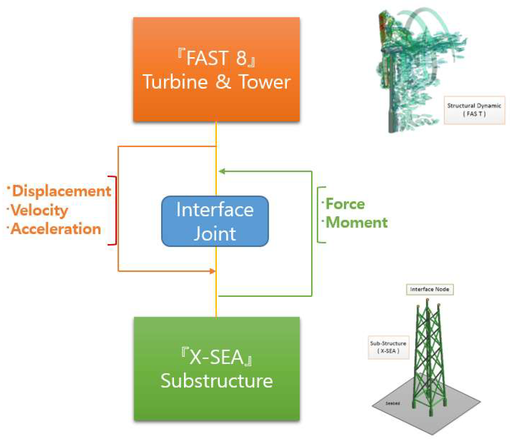
The coupled method is represented in this paper for solving the interaction behavior among the tower, turbine and substructure. The basic layout of the coupled method within the X-SEA program is obtained by loosening the coupling of substructure module of the FAST v8 program [27] and replaced by the X-SEA program instead as illustrated in Figure 2. At the interface nodes position of the X-SEA program, the displacement, rotation, velocity and acceleration are the input data from the structural dynamic module in the FAST v8 program. The reaction forces at the interface node are outputs from the X-SEA program for input to the structural dynamic module in the FAST v8 program. By following the above concept of exchanging motion and forces, it can be called a “coupled method”.

2.3. Pile-Soil-Structure Interaction

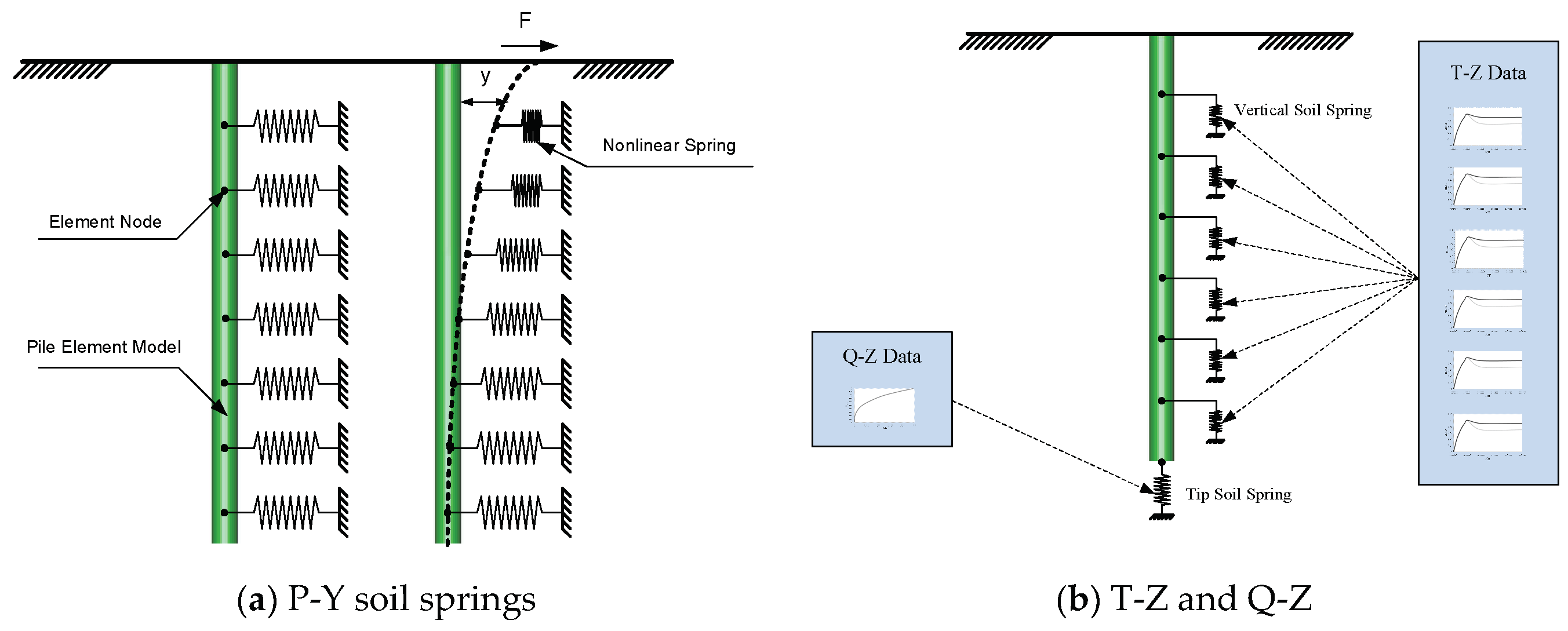
The length of the pile embedded in the seabed soil is termed pile penetration. The amount of pile penetration required that is needed to achieve the compression and tension (pullout) capacities necessary to support the offshore platform. The soil around the pile must resist lateral and axial bearing loads. As the nature of the soil is complicated to predict, finding a closed form solution to such a problem is extremely difficult. The American Petroleum Institute recommended practice [17] of the provided method for determining pile capacity for lateral and axial bearing loads in either clay or sandy soils. All the information on lateral and horizontal load was developed by laboratorians from the soil simple data called “P-Y, T-Z and Q-Z data” as shown in Figure 3 at specific offshore sites The basic concept of the pile was treated as a plastic laterally loaded beam. In reality, soil behavior should be predicted as a series of independent springs with nonlinear soil stiffness, in which the lateral stiffness at one point was affected by the lateral stiffness at other points along the depth of the pile. If the soil conditions at a support are different from the others, such variation should be taken in to account [28].
Two methods to predict the response of the composite pile-soil system can be used in an offshore structural analysis as follows:
(1)
The pile-soil-structure interaction (PSSI), the nonlinear soil behavior is simulated as a nonlinear soil spring by using P-Y, T-Z and Q-Z curve data according to the American Petroleum Institute.
(2)
The pile-soil interaction (PSI), similar to the pile-soil-structure interaction, the pile-soil interaction simulated the nonlinear soil behavior using P-Y, T-Z and Q-Z curve as a nonlinear soil spring.
The axial load pile takes into account the T-Z and Q-Z curve data and is converted to vertical and tip soil spring stiffness as shown in Figure 3.

3. Numerical Examples

3.1. Verification of Jacket Support Structure for NREL 5MW Offshore Wind Turbine

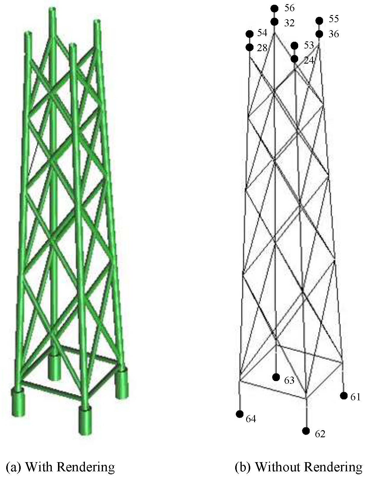
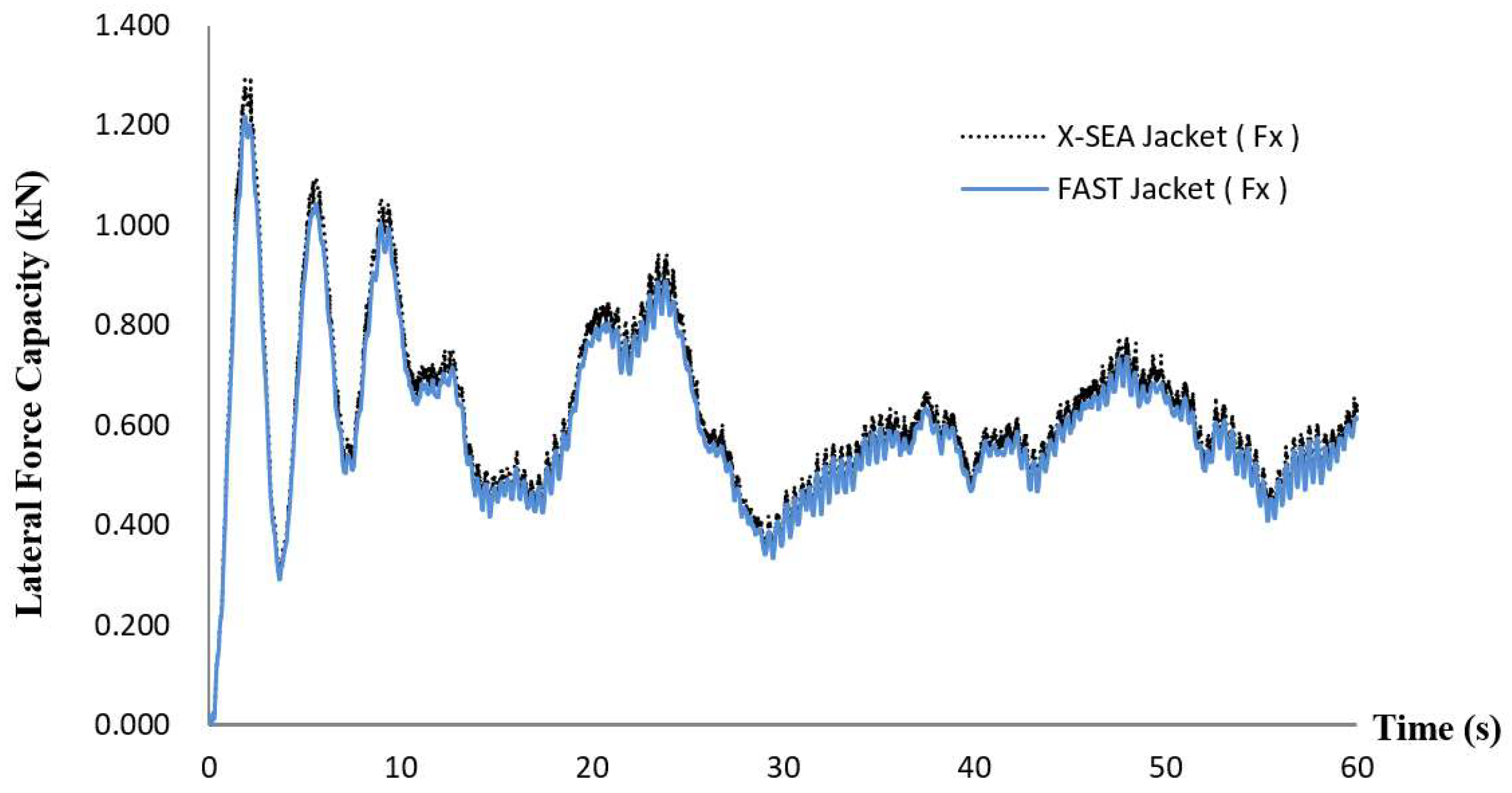
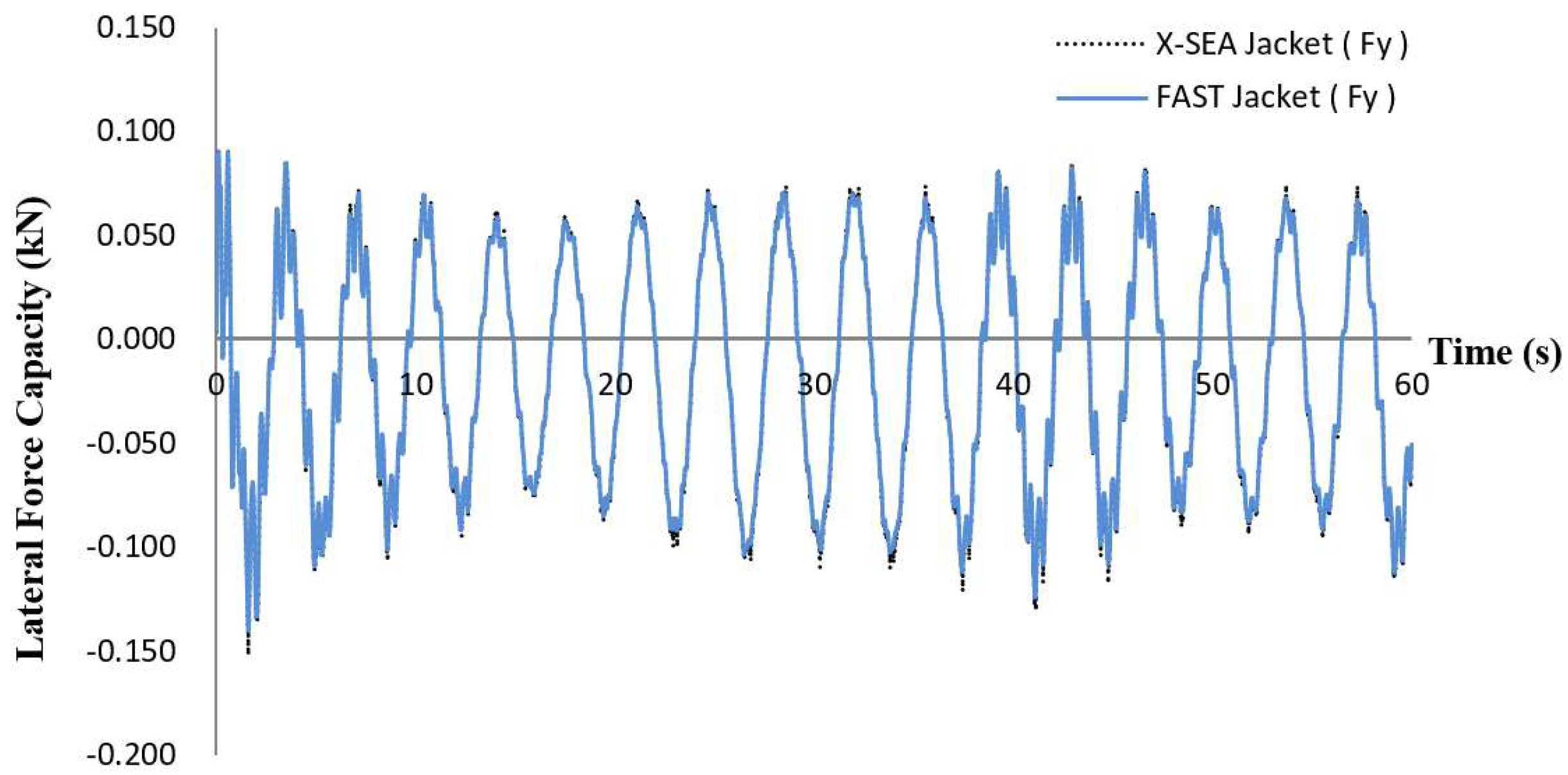
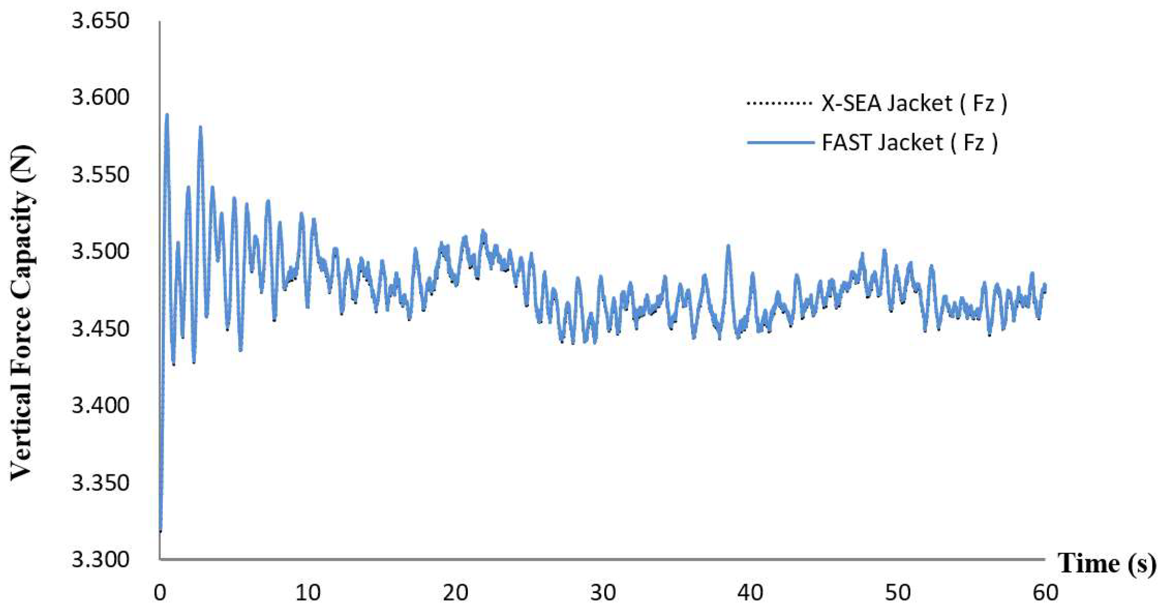
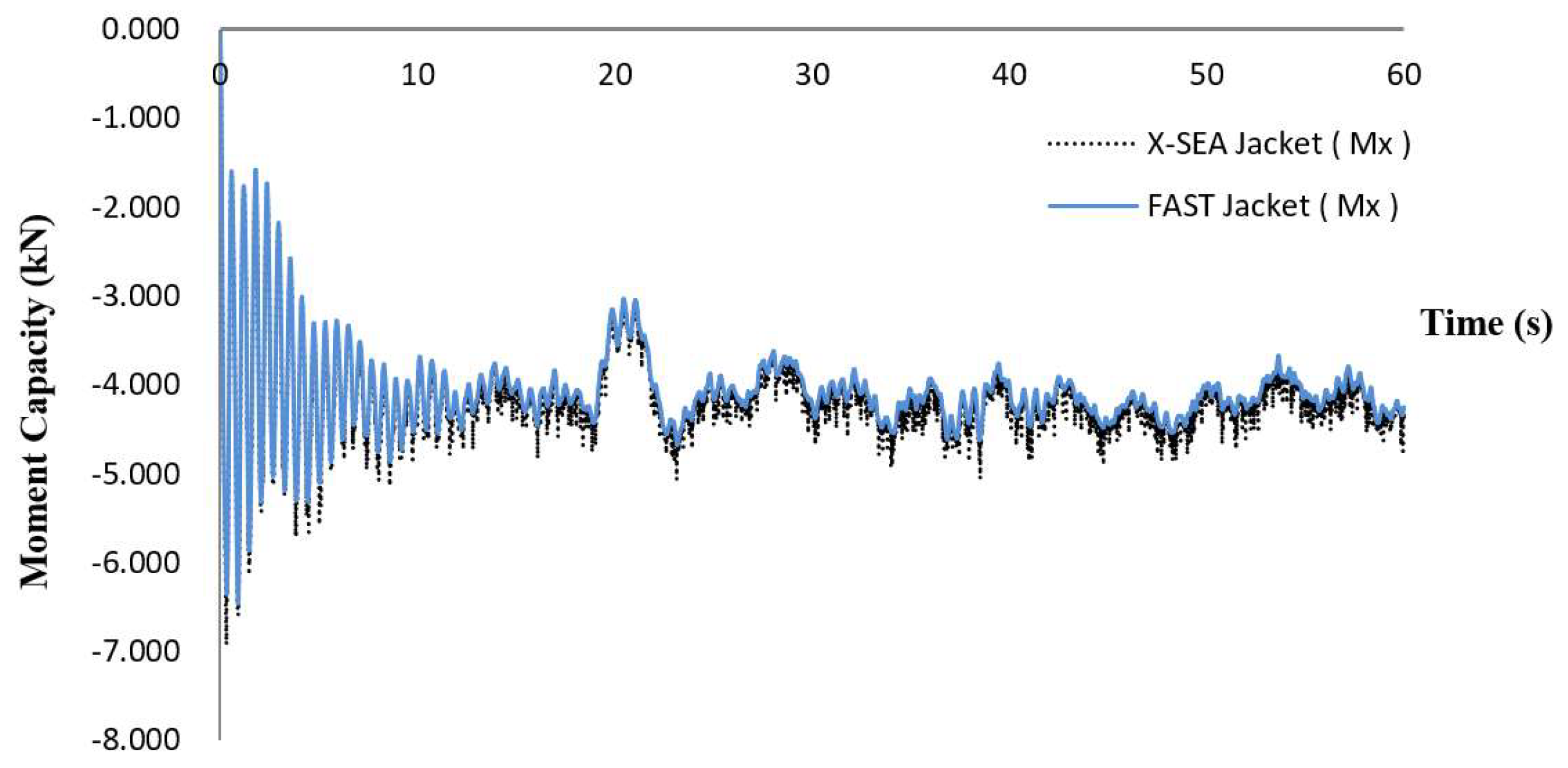
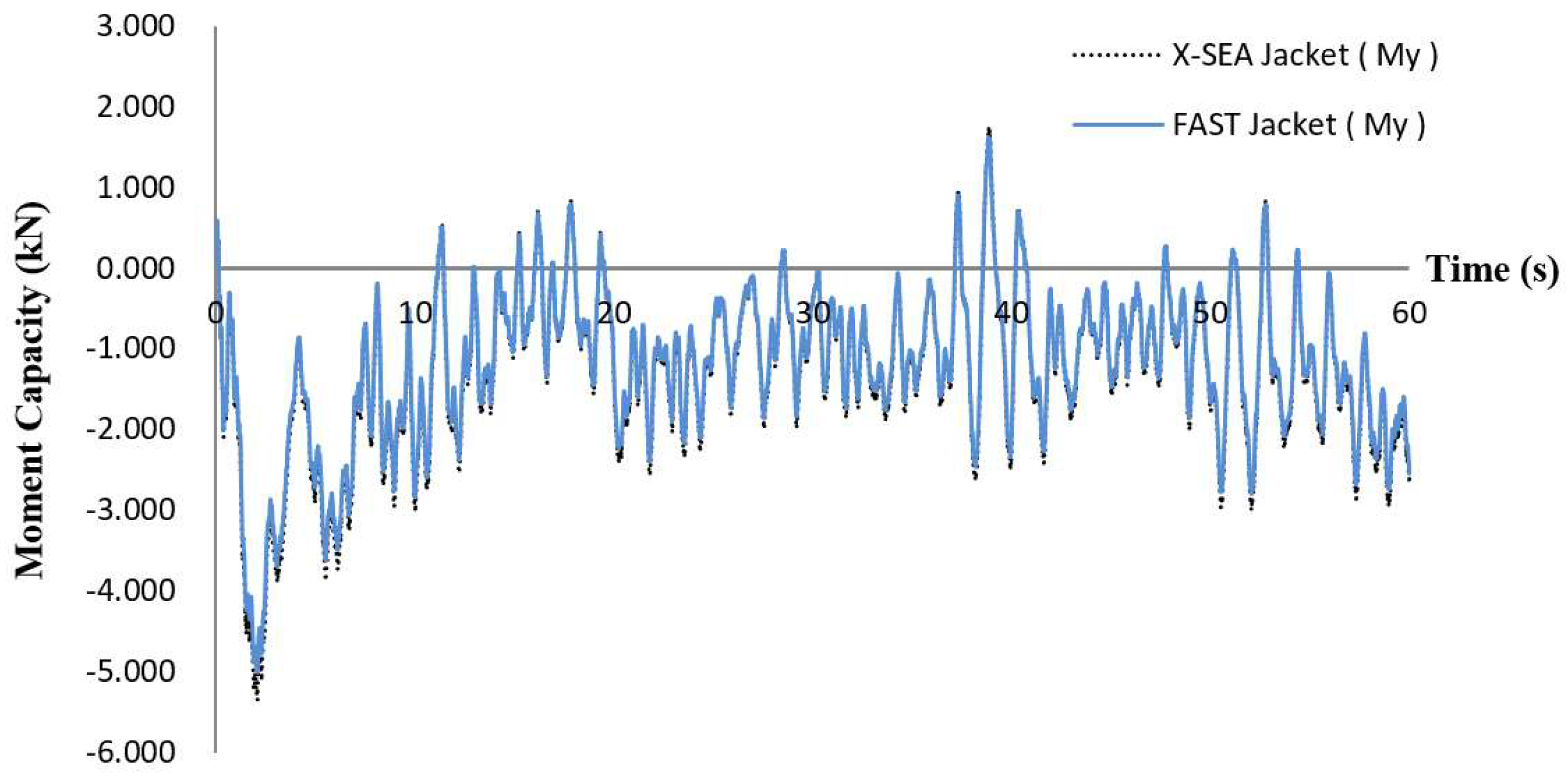
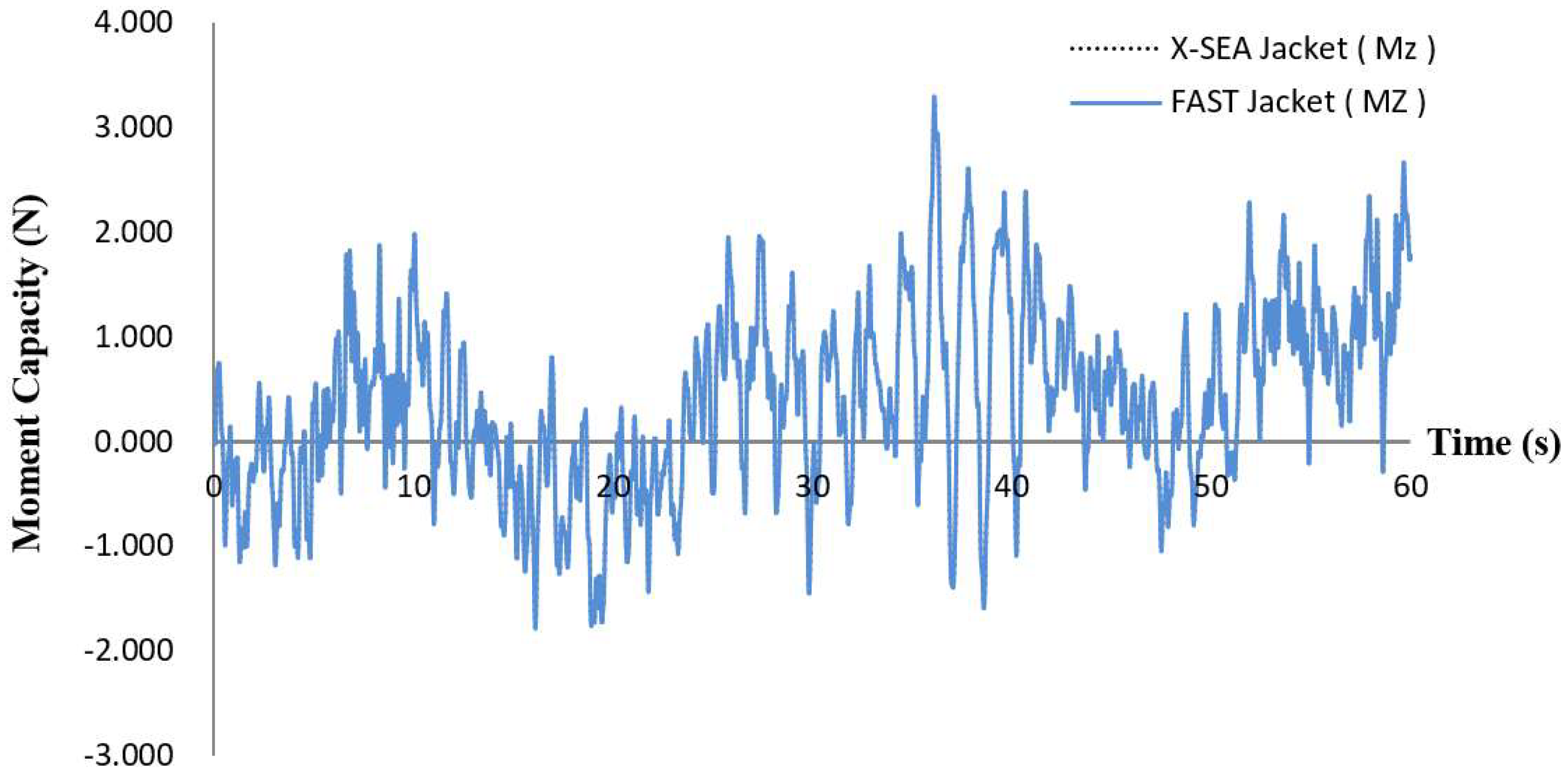
The jacket support structure of the OWT, which was studied in the US National Renewable Energy Laboratory (NREL), was located on the seabed with a fixed boundary condition, had 70.15 m height driven into 50 m water depth and extended 20.15 m above the mean sea level. The mean wind speed was 14 m/s. The support structure corresponded to periodic wave kinematics of 8 m significant wave height and 10 sec period of wave, where the water density was 1025 kg/m3. The jacket foundation model is illustrated in Figure 4. Thar model has 12 joints and 112 elements. The joint numbers 61–64 were the fixed boundary conditions located on the seabed. The joint numbers 24, 28, 32, 36, 54, 55 and 56 were the transition pieces or interface joints to transfer the loads and motions within the X-SEA program. The geometry and material properties of the jacket structure are given in Table 3. The same wave forces produced by Airy wave theory were applied to both X-SEA and FAST v8 substructure models [9]. The resulted dynamic lateral reaction forces in the x- and y-directions and the vertical reaction force in the z-direction are compared in Figure 5, Figure 6 and Figure 7, respectively. Figure 8, Figure 9 and Figure 10 compare the resulted dynamic reaction moment capacity on the jacket support structure about x-, y- and z-directions, respectively. These reaction forces and moments resulted from X-SEA and FAST v8 substructure models in good agreement.

3.2. Coupled Dynamic Analysis of Turbine and Support Structure

In this example, the coupled analysis of the NREL 5MW offshore wind turbine and the jacket support structure as mentioned in Section 3.1 was performed. The four piles supporting the jacket structure were fixed on the seabed. The support structure with 70.15 m height drove through a 50 m water depth and extended 20.15 m above the mean sea level. The environmental conditions with 2.8 m wave height and 6.07 seconds wave period were taken into account.
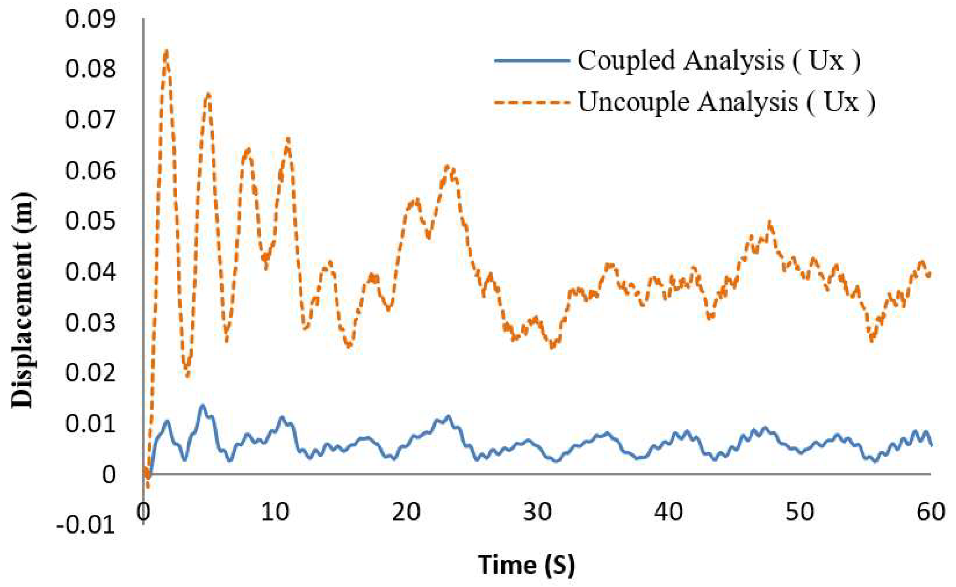
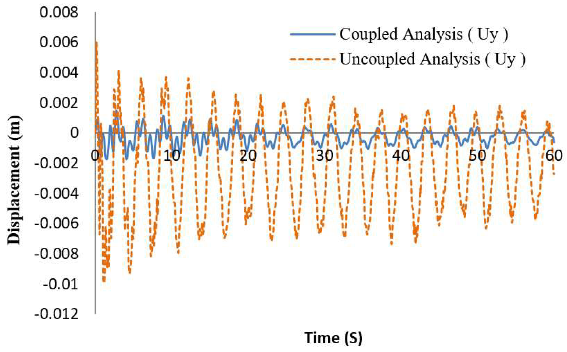
The X-SEA program was used to determine the hydrodynamic forces and calculate the responses of the substructure by interchanging the displacement, velocity, acceleration, force and moment at the interface point with the FAST v8 program. Between these two programs, these responses were exchanged using the present study module. The displacement of the coupled and uncoupled analysis method was monitored below the interface joint for obtaining the accurate responses of the structure in x- and y-directions as shown in Figure 11 and Figure 12. It is obvious from these plots that, in the coupled analysis the interaction between the support structure and the tower structure was accounted for, the averaged oscillation of the structure was therefore 6.9 times less than that of the uncoupled analysis. In addition, the coupled analysis of the turbine and structure produced a result close to the realistic behavior of a wind turbine in the test site, which includes the turbine effect while the computational time was only slightly different.

3.3. Dynamic Coupled Analysis of Turbine and Support Structure-Pile-Soil Interaction

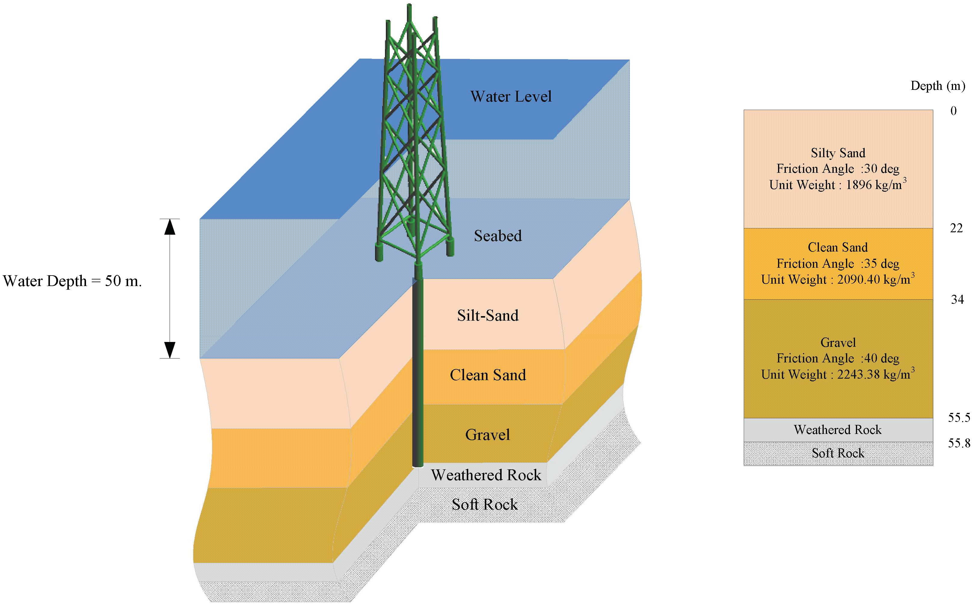
In this example, the coupled analysis of a NREL 5MW offshore wind turbine, jacket support structure and structure-pile-soil interaction was performed. The geometry and section properties of the jacket structure were mentioned in the above section. In this case, the pile head was connected with four cylindrical tubes of 55 m depth, 1.5 m diameter and 0.05 m thickness and penetrated the soil. The soil consisted of five layers with the property data given in Figure 13. The piled support structure was considered as the substructure and the soil behavior was predicted as nonlinear soil spring stiffness. The information of the soil stiffness was due to the P-Y, T-Z and Q-Z curve data specific offshore design standard. In addition, the second model of the piled support structure uses the super element concepts to reduce the matrix size and computation time. The basic concept is the condensation of three-dimensional soil stiffness to a single value.
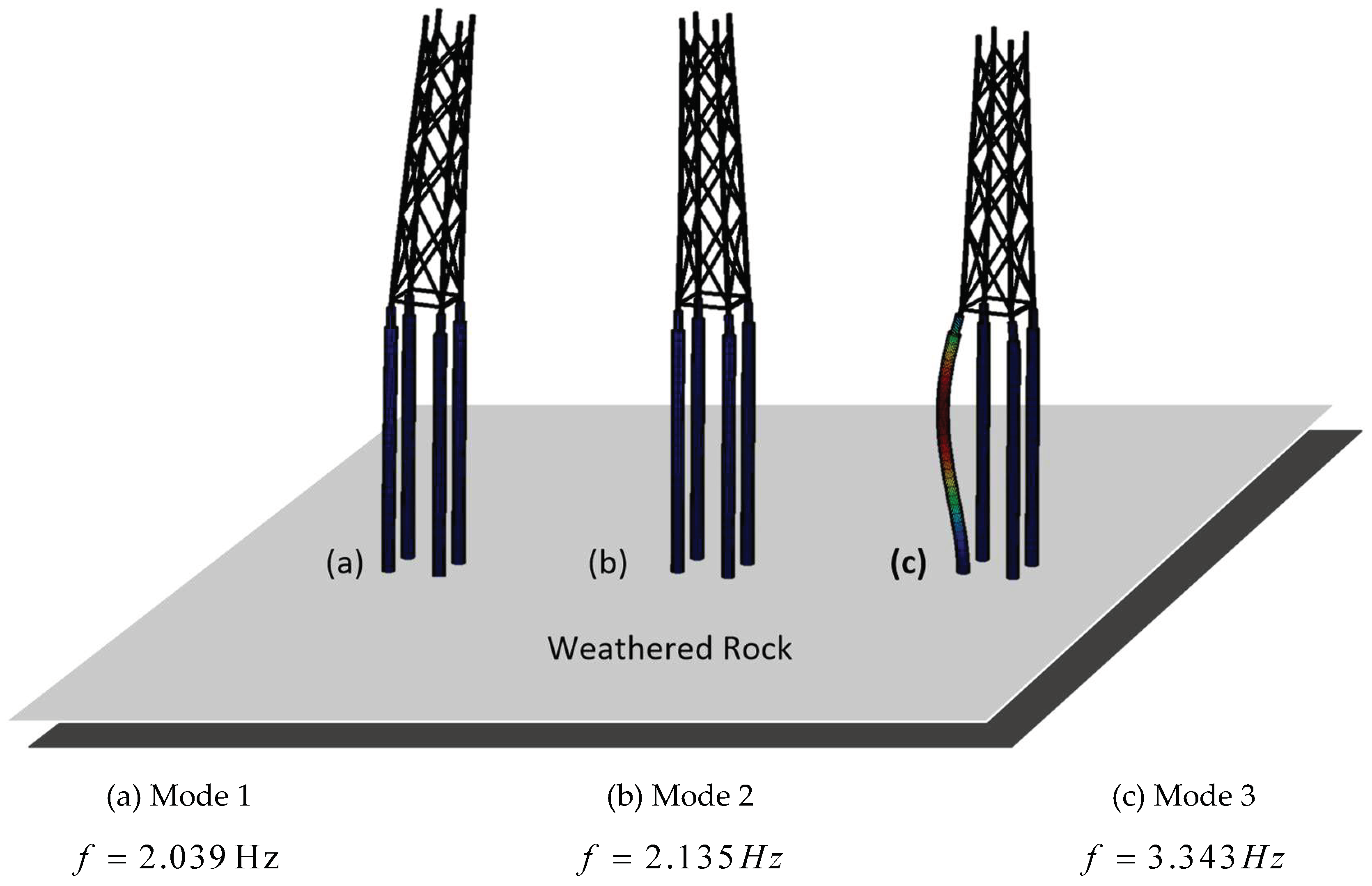
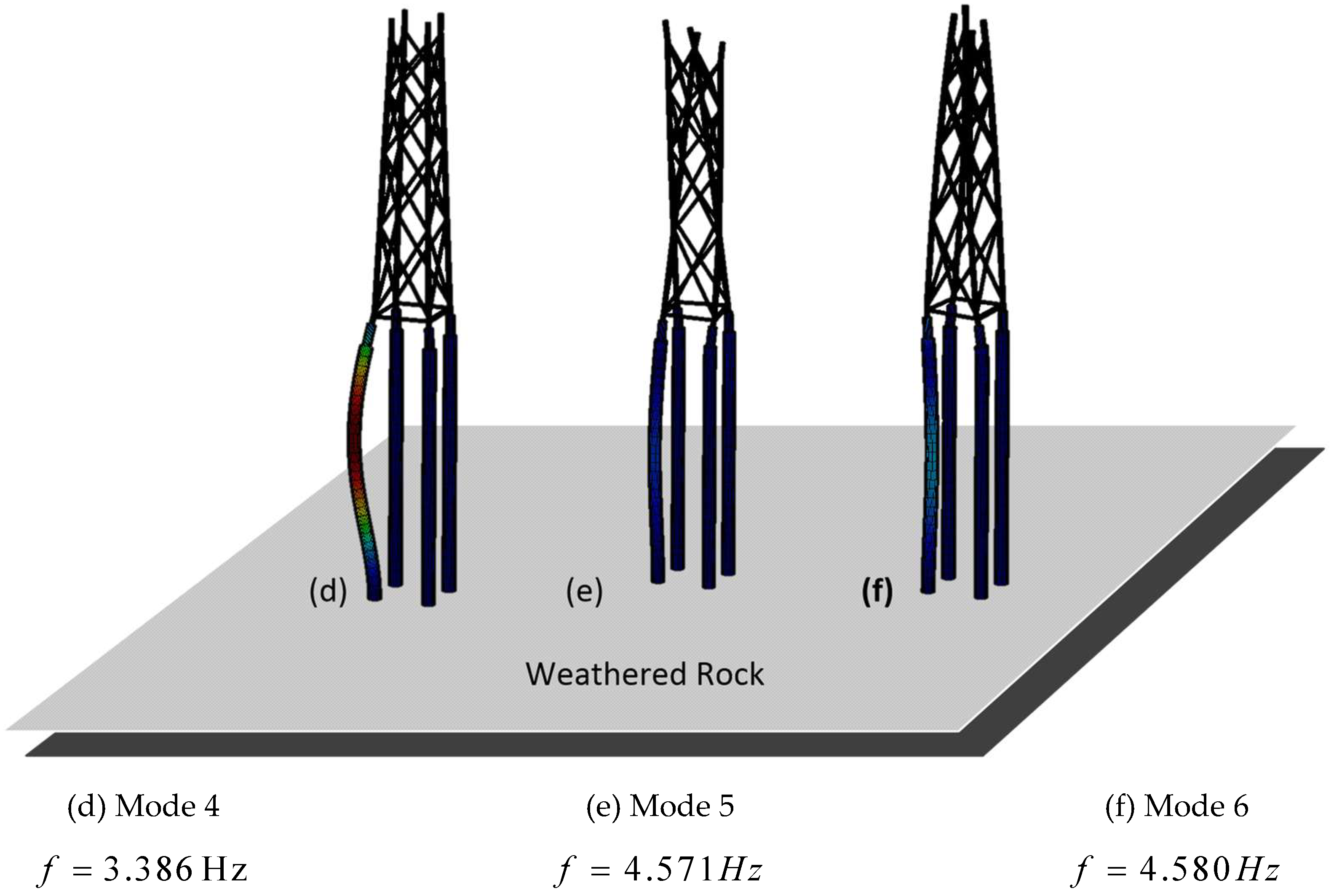
The natural frequency analysis of the piled support structure was carried out using the X-SEA program. This analysis was proposed to avoid a non-stationary load, which causes the system resonance when excitation due to the environmental load and natural frequencies being closer to the design chart. The model of the frequency analysis provides the six modes as illustrated in Figure 14. The scaling factor of 25 was used to amplify the jacket support structure shape in the X-SEA program. In the first mode, the jacket support structure was oscillating globally in the x-direction. The mode shape was the movement of the whole structure with a natural frequency of 2.039 Hz as illustrated in Figure 14a. The second mode shapes were slightly different with a natural frequency of 2.135 Hz and oscillated globally in the opposite x-direction as illustrated in Figure 14b. In the third mode shape, which was the bending mode of the pile structure and without the effect of a whole structure with a natural frequency of 3.343 Hz as illustrated in Figure 14c. The fourth mode shape with a natural frequency of 3.386 Hz had a similar shape to the third mode was oscillating globally in the z-direction as illustrated in Figure 14d.
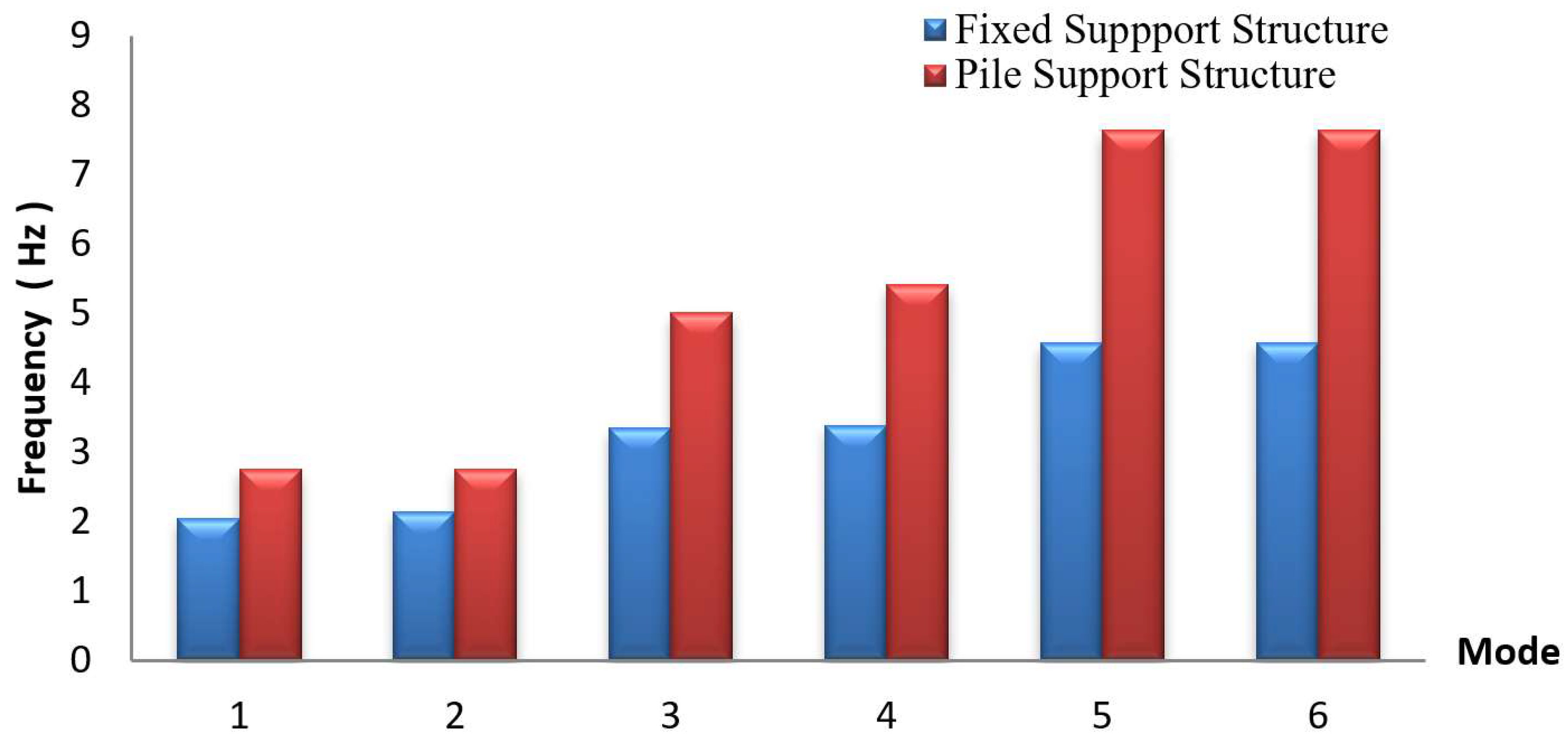
The fifth mode shape was a torsional mode about the z-direction, where twisting occurred along the structure at the free to end boundary condition with a natural frequency of 4.571 Hz as illustrated in Figure 14e. Whereas the sixth mode shape with a natural frequency of 4.58 Hz was a combination mode due to twisting along the support structure and insignificance at the pile structure as shown in Figure 14f. By comparing the natural frequencies of the fixed support structure, it was obvious that those of the piled-support structure increased 1.351, 1.291, 1.497, 1.599, 1.670 and 1.667 times, respectively, as illustrated in Figure 15. The significant differences in natural frequencies were attributed to the self-weight and soil stiffness along the pile length. It could be concluded that a larger self-weight and soil stiffness leads to the increase in excitation but a decrease in the natural frequencies of the structure.
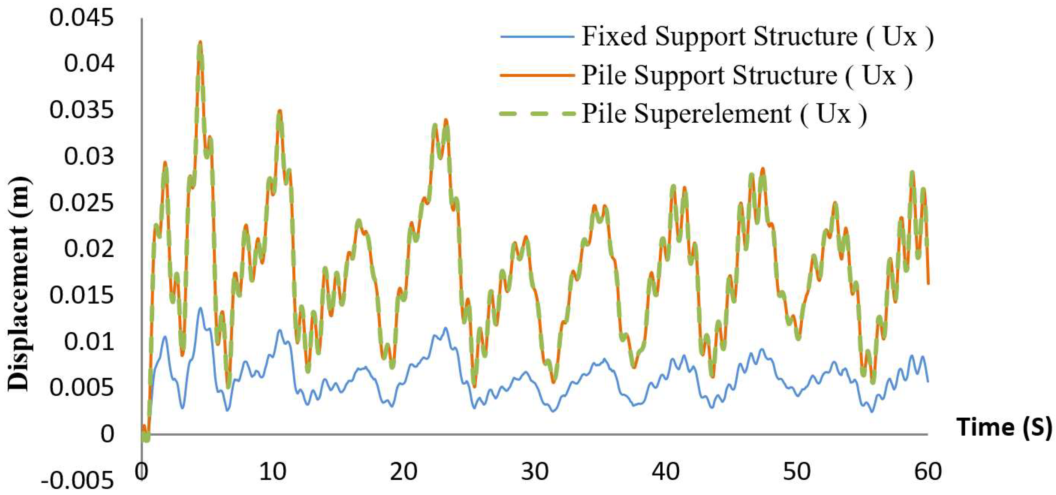
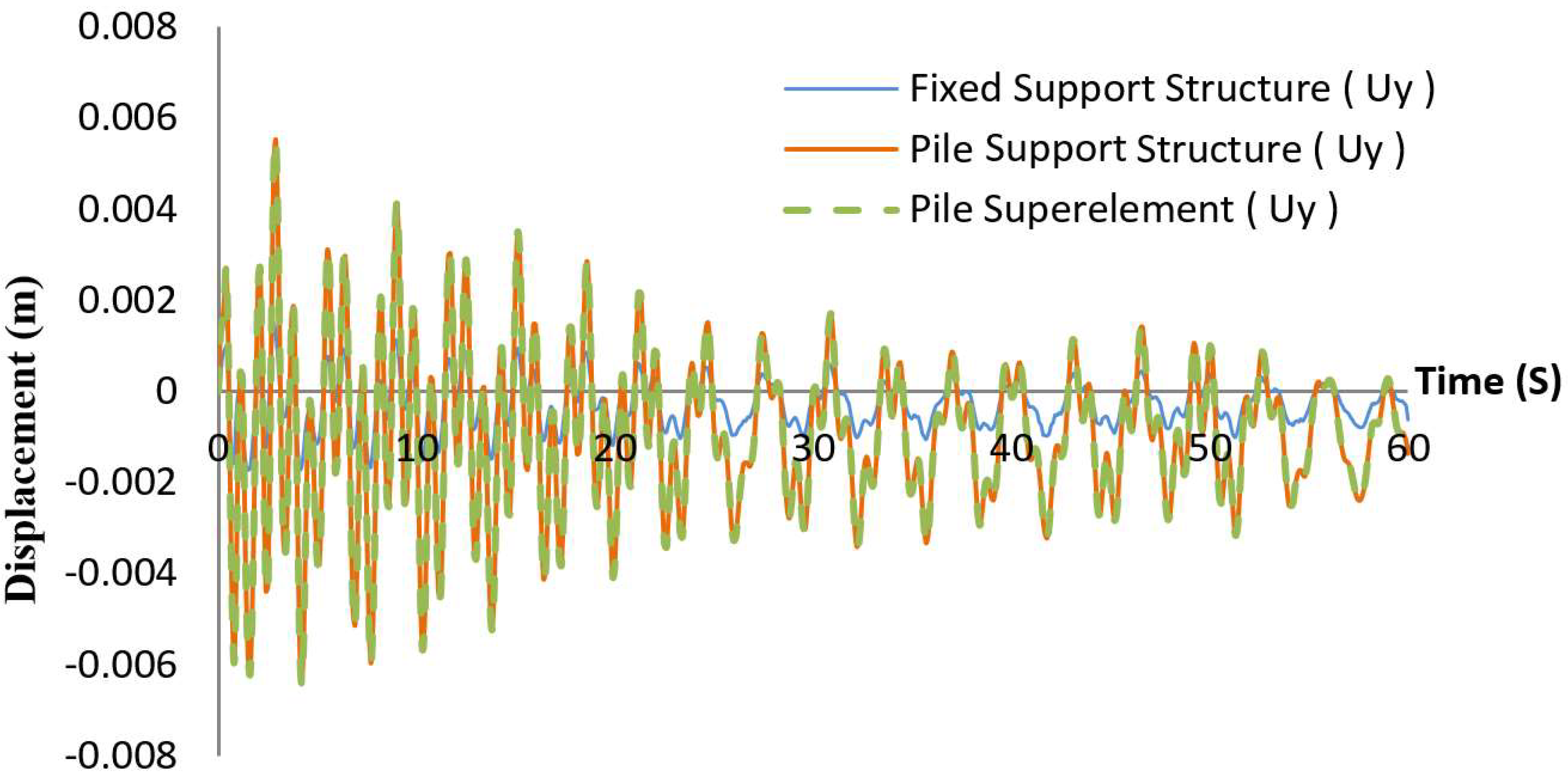
Compared with the fixed support structure, the piled support structure produced a more flexible response with 3.83 times in terms of the maximum values as shown in Figure 16 and Figure 17. The results of the pile using the superelement were identical to that of the piled support structure. Whereas, the resulted displacements in the y-direction had a similar trend as the x-direction but increased 3.13 times in terms of the peak values. It can be concluded that the responses of the piled support structure was significantly influenced by the environmental load, turbine responses, structural stiffness and nonlinear three-dimensional soil spring stiffness. The results predicted by using PSSI were therefore more accurate.
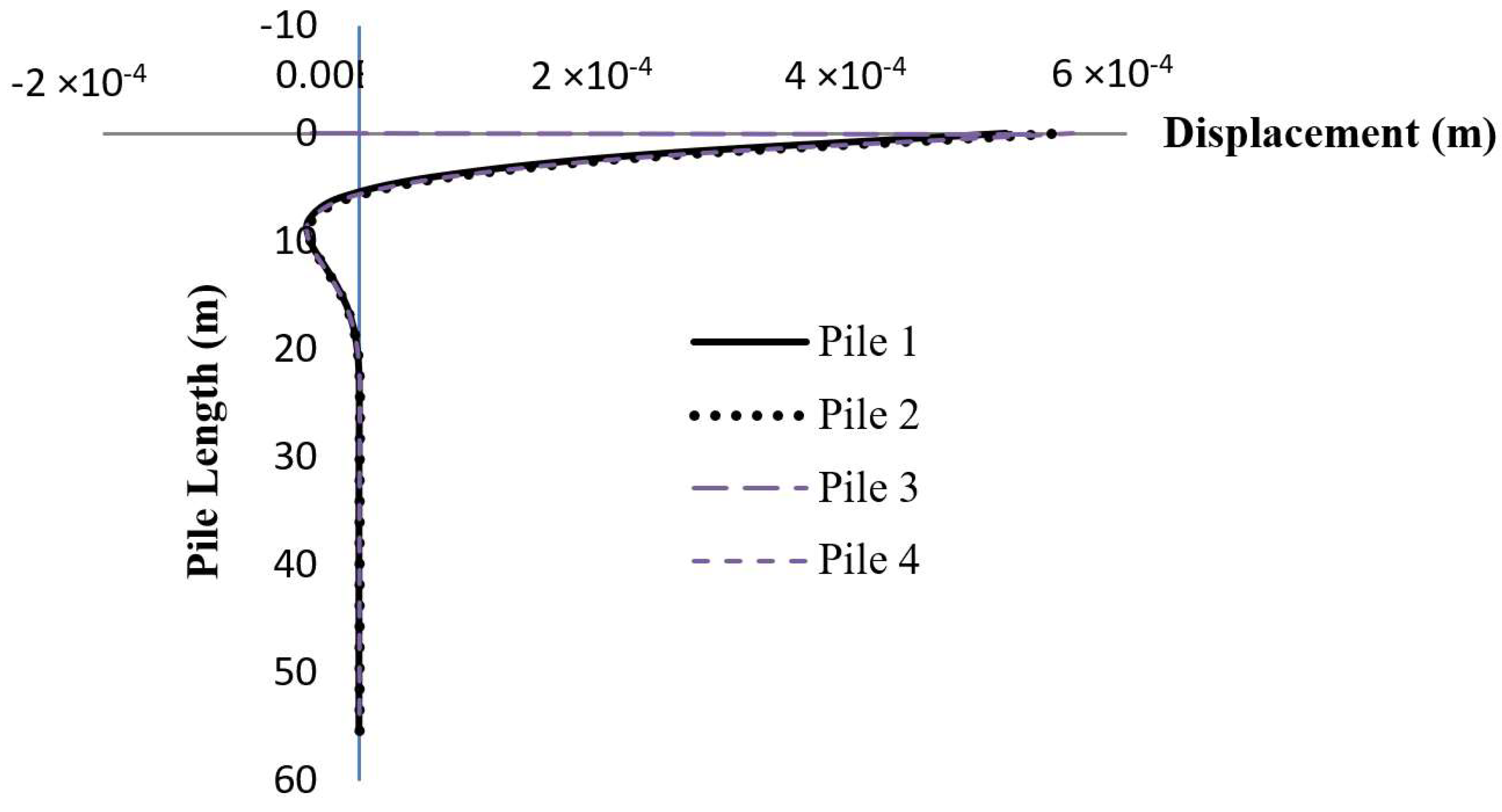
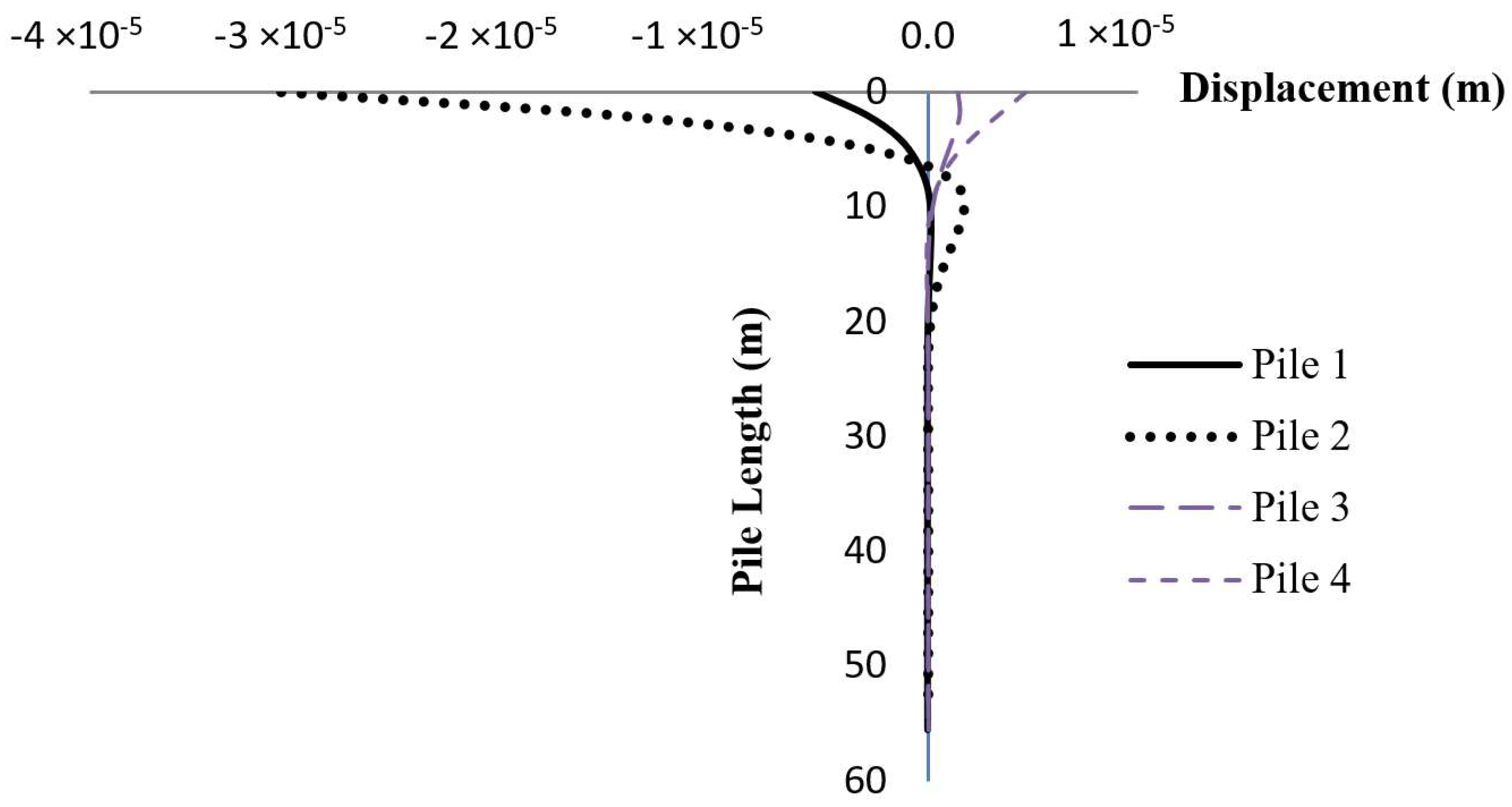
When the external load acts on the foundation, the structure should be sustainable. While the loads were transferring through to the piles via their end bearing and soil skin friction and by a pile curves response in the lateral and transverse directions, as in Figure 18 and Figure 19, the maximum lateral displacement of 0.00024 m occurred at the analysis time of 4.5 seconds. The maximum transverse displacement of 0.0000405 m occurred at the analysis time of 4.2 seconds. It can be concluded that the piled support structure is capable to hold and resist the external forces beyond the plastic limits of soil.

4. Concluding Remarks

Reliable and computationally efficient evaluation of the complex system of jacket foundation-offshore wind turbine remains an issue. Theoretical formulation and simulations of the coupled analysis between the wind turbine and jacket support structure including the pile soil structure interaction (PSSI) have been therefore presented. A case study of a NREL 5MW offshore wind turbine on a jacket support structure has been performed. By replacing the sub-structural module in the FAST v8 program with the offshore substructure component in the X-SEA program, the reaction forces and moments were calculated in each time step and compared with those resulted from the FAST v8 program. It showed very good agreement with each other. In the coupled analysis of the fixed-support structure, the interaction between the hydrodynamic forces and the tower structure was accounted for and the averaged oscillation of the structure was 6.9 times less than that of the uncoupled analysis.
The parametric study of the fully coupled analysis with PSSI has then been carried out. The results showed that the soil stiffness increased the excitation but decreased the natural frequencies of the structure. The significant differences were related with the self-weight or mass, number degree of freedom and stiffness in the equation of motion. The support structure considering PSSI exhibited a more flexible response compared to the fixed-support structure. The coupled analysis including PSSI was shown to be more accurate and time-efficient as it could characterize the three-dimensional nonlinear stiffness of soil and the influence of environmental loads more properly.

Author Contributions

Formal analysis, P.P.; Investigation, P.P.; Validation, P.P.; Conceptualization, V.N.D. and K.-D.K.; Methodology, V.N.D. and K.-D.K.; Writing—original draft preparation, P.P. and V.N.D.; Writing—review and editing, V.N.D. and K.-D.K.; Funding acquisition, K.-D.K.

Funding

This work is supported by Korea Electric Power Corporation (Development of analysis program of offshore wind turbine structure and design example using FAST turbine aerodynamic load). This work was supported by the Technology Innovation Program (10077981, Software for the analysis and design of fixed offshore structures) funded by the Ministry of Trade, Industry & Energy (MOTIE, Korea). The second author (V. N. Dinh) has been funded by Science Foundation Ireland (SFI) Research Centre: MaREI - Centre for Marine and Renewable Energy (12/RC/2302). The authors are grateful for the support.

Conflicts of Interest

The authors declare no conflict of interest.

References

  1. Chen, I.-W.; Wong, B.-L.; Lin, Y.-H.; Chau, S.-W.; Huang, H.-H. Design and analysis of jacket substructures for offshore wind turbines. Energy 2016, 9, 264. [Google Scholar] [CrossRef]
  2. Dinh, V.N.; Basu, B. On the modeling of spar-type floating offshore wind turbines. Key Eng. Mater. 2013, 569–570, 636–643. [Google Scholar] [CrossRef]
  3. Schaumann, P.; Böker, C. Can jackets and tripods compete with monopiles? In Proceedings of the Copenhagen Offshore Wind, Copenhagen, Denmark, 26–28 October 2005. [Google Scholar]
  4. Zaaijer, M.B. Comparison of monopile, tripod, suction bucket and gravity base design for a 6 MW turbine. In Proceedings of the Offshore Windenergy in Mediterranean and Other European Seas (OWEMES Conference), Naples, Italy, 10–12 April 2003. [Google Scholar]
  5. Jonkman, J.; Butterfield, S.; Musial, W.; Scott, G. Definition of a 5-MW Reference Wind Turbine for Offshore System Development; Technical report, NREL/TP-5000-38060; National Renewable Energy Laboratory (NREL): Golden, CO, USA, February 2009. [Google Scholar]
  6. Lozano-Minguez, E.; Kolios, A.J.; Brennan, F.P. Multi-criteria assessment of offshore wind turbine support structures. Renew. Energy 2011, 36, 2831–2837. [Google Scholar] [CrossRef] [Green Version]
  7. Ong, M.C.; Bachynski, E.E.; Økland, O.D.; Passano, E. Dynamic responses of a jacket-type offshore wind turbine using decoupled and coupled models. In Proceedings of the ASME 2014 33rd International Conference on Ocean, Offshore and Arctic Engineering (OMAE2014), San Francisco, CA, USA, 8–13 June 2014. [Google Scholar]
  8. Voormeeren, S.N.; van der Valk, P.L.C.; Nortier, B.P.; Molenaar, D.-P.; Rixen, D.J. Accurate and efficient modeling of complex offshore wind turbine support structures using augmented superelements. Wind Energy 2014, 17, 1035–1054. [Google Scholar] [CrossRef]
  9. Plodpradit, P. The Coupled Analysis of Offshore Wind Turbine Structure with Pile-Soil-Structure Interaction, Department of Civil and Environmental System Engineering. Ph.D. Thesis, Konkuk University, Seoul, Korea, 2017. [Google Scholar]
  10. Kim, K.-D.; Vachirapanyaku, S.; Plodpradit, P.; Dinh, V.N.; Park, J.-H. Development of offshore structural analysis software X-SEA and FAST. In Proceedings of the 38th International Conference on Ocean, Offshore & Arctic Engineering, ASME 2019 OMAE 2019-96778, Glasgow, Scotland, UK, 9–14 June 2019. [Google Scholar]
  11. Jonkman, J. FAST v8. National Renewable Energy Laboratory (NREL): Golden, CO, USA, 2018. Available online: https://nwtc.nrel.gov/FAST8 (accessed on 1 May 2014).
  12. Ali, A.A.M.; Al-Kadhimi, A.; Shaker, M. Dynamic behavior of jacket type offshore structure. Jordan J. Civ. Eng. 2012, 6, 418–435. [Google Scholar]
  13. Raheem, S.E.A.; Abdel Aal, E.M.A.; Abdel Shafy, A.G.A.; Abdel Seed, F.K. Nonlinear analysis of offshore structures under wave loadings. Eng. Sci. 2012, 40, 673–687. [Google Scholar]
  14. Raheem, S.E.A. Nonlinear response of fixed jacket offshore platform under structural and wave loads. Coupled Syst. Mech. 2013, 2, 111–126. [Google Scholar] [CrossRef]
  15. Matlock, H. Correlation for design of laterally loaded piles in soft clay. In Proceedings of the Offshore Technology in Civil Engineering, Houston, TX, USA, 22–24 April 1970. [Google Scholar]
  16. O’Neill, M.W.; Murchinson, J.M. An Evaluation of p-y Relationship in Sand; American Petroleum Institute Report for University of Houston: Houston, TX, USA, May 1983. [Google Scholar]
  17. American Petroleum Institute. Recommended Practice for Planning, Designing and Constructing Fixed Offshore Platforms-Working Stress Design, API Recommended practice 2A-WSD. December 2007. Available online: http://latorebondeng90245.tripod.com/api_rp2a.pdf (accessed on 9 April 2019).
  18. Mostafa, Y.E.; Naggar, M.H.E.L. Response of fixed offshore platform to wave and current loading including soil-structure interaction. Soil Dyn. Earthq. Eng. 2004, 24, 357–368. [Google Scholar] [CrossRef]
  19. Kim, K.D.; Suthasupradit, S.; Kim, Y.H.; Lomboy, G.R.; Dinh, V.N. New development of XFINAS software for nonlinear dynamic and seismic analysis of structures. In Proceedings of the Third Asian-Pacific Congress on Computational Mechanics (APCOM’07) & the Eleventh International Conference on the Enhancement and Promotion of Computational Methods in Engineering and Science (EPMESC XI), Kyoto, Japan, 2007. [Google Scholar]
  20. Kim, K.D.; Plodpradit, P.; Manovachirasan, A.; Sinsabvarodom, C.; Kim, B.-J. Analysis of offshore structures for wind turbines and oil and gas using X-SEA software. In Proceedings of the 11th World Congress on Computational Mechanics (WCCM XI), 5th European Conference on Computational Mechanics (ECCM V), 6th European Conference on Computational Fluid Dynamics (ECFD VI), Barcelona, Spain, 20–25 July 2014. [Google Scholar]
  21. American Petroleum Institute. Recommended Practice for Planning, Designing and Constructing Fixed Offshore Platforms-Load and Resistance Factor Design, API Recommended practice 2A-LRFD; API Recommended Practice 2A-LRFD; American Petroleum Institute: Washington, DC, USA, 1993. [Google Scholar]
  22. GID, Cimne, 2016. Available online: https://www.gidhome.com (accessed on 5 January 2017).
  23. Dawson, T.H. Offshore Structure Engineering; Prentice-Hall, Inc.: Englewood Cliffs, NJ, USA, 1983. [Google Scholar]
  24. Sarpkaya, T.; Isaacson, M. Mechanics of Wave Force on Offshore Structure; Van Nostrand Rehold Company: New York, NY, USA, 1981. [Google Scholar]
  25. Basu, B.; Staino, A.; Dinh, V.N. Vibration of wind turbines under seismic excitations. In Proceedings of the Fifth Asian-Pacific Symposium on Structural Reliability and its Applications, Singapore, 23–25 May 2012. [Google Scholar] [CrossRef]
  26. Dinh, V.N.; McKeogh, E. Offshore wind energy: Technology opportunities and challenges. In Proceedings of the First Vietnam Symposium on Advances in Offshore Engineering, Lecture Notes in Civil Engineering, Hanoi, Vietnam, 1–3 November 2018; 18, pp. 3–22. [Google Scholar] [CrossRef]
  27. Damiani, R.; Jonkman, J.; Hayman, G. SubDyn User’s Guide and Theory Manual; National Renewable Energy Laboratory (NREL): Golden, CO, USA, March 2015. [Google Scholar]
  28. Dinh, V.N.; Basu, B.; Brinkgreve, R.B.J. Wavelet-based evolutionary response of multi-span structures including wave-passage and site-response effects. J. Eng. Mech. 2014, 140, 04014056-1-12. [Google Scholar] [CrossRef]
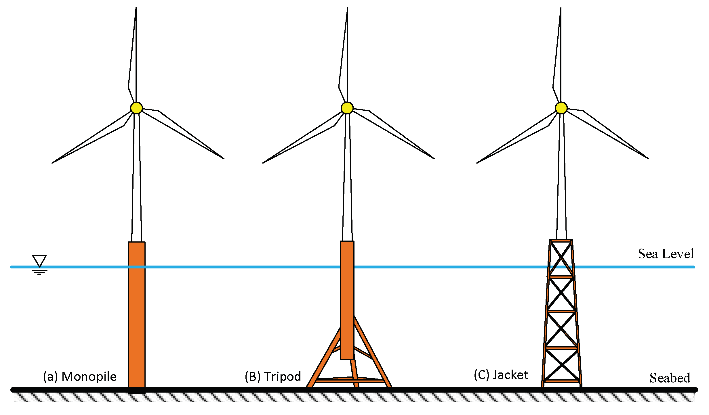
Figure 1. Different types of wind turbine offshore foundations.
Applsci 09 01633 g001
Figure 2. Basis layout of the structure module within X-SEA.
Applsci 09 01633 g002
Figure 3. Soil-pile interaction model.
Applsci 09 01633 g003
Figure 4. NREL 5MW jacket support structure model.
Applsci 09 01633 g004
Figure 5. Comparison of the dynamic lateral reaction force capacity on the jacket support structure in the x-direction resulted from X-SEA and FAST v8 programs.
Applsci 09 01633 g005
Figure 6. Comparison of the dynamic lateral reaction force capacity on the jacket support structure in the y-direction resulted from X-SEA and FAST v8 programs.
Applsci 09 01633 g006
Figure 7. Comparison of the dynamic vertical reaction force capacity on the jacket support structure in the z-direction resulted from X-SEA and FAST v8 programs.
Applsci 09 01633 g007
Figure 8. Comparison of the dynamic reaction moment capacity on the jacket support structure about the x-direction resulted from X-SEA and FAST v8 programs.
Applsci 09 01633 g008
Figure 9. Comparison of the dynamic reaction moment capacity on the jacket support structure about the y-direction resulted from X-SEA and FAST v8 programs.
Applsci 09 01633 g009
Figure 10. Comparison of the dynamic vertical reaction moment capacity on the jacket support structure about the z-direction resulted from X-SEA and FAST v8 programs.
Applsci 09 01633 g010
Figure 11. Comparison of displacements in the x-direction resulted from coupled and uncoupled analyses from the X-SEA program.
Applsci 09 01633 g011
Figure 12. Comparison of displacement in the y-direction resulted from coupled and uncoupled analyses from the X-SEA program.
Applsci 09 01633 g012
Figure 13. The jacket support structure with the pile-soil-structure interaction (PSSI) model.
Applsci 09 01633 g013
Figure 14. The natural frequencies and mode shape of piled support structure (scaling factor = 25).
Applsci 09 01633 g014aApplsci 09 01633 g014b
Figure 15. A comparison of the natural frequencies between the piled support structure and fixed support structure.
Applsci 09 01633 g015
Figure 16. A comparison of the displacement on the fixed support structure, piled-support structure and pile superelement models in the x-direction.
Applsci 09 01633 g016
Figure 17. A comparison of the displacement on the fixed support structure, pile support structure and pile superelement models in the y-direction.
Applsci 09 01633 g017
Figure 18. The maximum distribution of displacement along the pile length in the lateral direction (x).
Applsci 09 01633 g018
Figure 19. The maximum distribution of displacement along the pile length in the transverse direction (y).
Applsci 09 01633 g019
Table 1. Offshore structural analysis options of X-SEA.
Solution Features of X-SEA
Environmental load (wave, current, wind, marine growth, buoyancy, earthquake, self-weight etc.)
Regular (five kinds) and irregular wave (PM and JONSWAP Spectrum)
3D linear diffraction wave theory (shell and solid element)
Static analysis with load combinations
Frequency analysis
Three-dimensional prestressed concrete analysis using 3D solid and shell element
Geometrical and material nonlinear analysis of frame, shell and solid elements
Nonlinear time history dynamics (dynamics of large deformation of elastoplastic analysis using frame, shell and solid elements)
Pile-soil-interaction foundation analysis (P-Y, T-Z and Q-Z)
Dynamic analysis in time domain and frequency domain
COG (center of gravity)
Automatic calculation of Stress Concentration Factor (SCF) with local joint flexibility
Fatigue damage analysis in time and frequency domain
Mooring analysis with seabed contact for floating offshore structures
Multiple calculation of FAST v8 wind turbine loads
Coupled analysis of FAST v8 and offshore structural analysis
Code checking (AISC, API, Euro Code 3, Norsok, DNV and IEC wind)
Table 2. Element Library of X-SEA.
Hydrodynamic Analysis
X-SEA Element Material Property
Shell elementXSHELL3-QSI: 3 node quasi-conforming
XSHELL4-ANS: 4 node assume natural strain
Elastoplastic: Von Mises with strain hardening, Ivanov-Yulishin,
Concrete elasto-plastic and elasto-plastic fracture, laminate composite, concrete creep
Frame elementXFRAME: 2 node frame element with warping (7 dof, shear deformation, tapered, offset)Elasto-plastic: Von Mises, concrete creep
Solid elementXSOLID4T & XSOLID10T: 4 and 10 node, tetrahedral
XSOLID8-EAS: EAS 8 node
Elasto-plastic: Von Mises, Mohr-Coulomb, Drucker-Prager, Tresca
Truss elementXTRUSS: 2 node three-dimensional elementElasto-plastic: Von Mises
Cable elementXCABLE–Parbolic
XCABLE–Catenary
XCABLE-Mooring
5-point nonlinear model
Spring elementXSPRING: 3D Spring
Link ElementGap, hook, gap-hook
Interface element1D, 2D, 3D (bond-slip element)
Tendon element3D prestressing tendon
Table 3. Geometry and material properties of the jacket support structure.
ParameterValue
Outer diameter of a leg [m]1.200
Wall thickness of a leg [m]0.045
Outer diameter of a diagonal [m]0.800
Wall thickness of a diagonal [m]0.035
Young’s modulus [N/m2]2.1 × 1011
Density [kg/m3]7850