BIM-Based AR Maintenance System (BARMS) as an Intelligent Instruction Platform for Complex Plumbing Facilities


Abstract
1. Introduction
- Introduction;
- Related works: the progress of AR and its applications in FM and BIM;
- Research purpose;
- BIM-based AR Maintenance System (BARMS): the development process, framework, and functions of the system;
- Experiment design: the design, task, and site of the experiment;
- 5.1.
- Encountered problems in preliminary tests;
- 5.2.
- Systems and location to be experimented;
- 5.3.
- Experiment procedures;
- Experiment result: PSSUQ analysis;
- Discussion: further discussion of the experimental results and related issues;
- Conclusions.
2. Related Works
3. Research Purpose
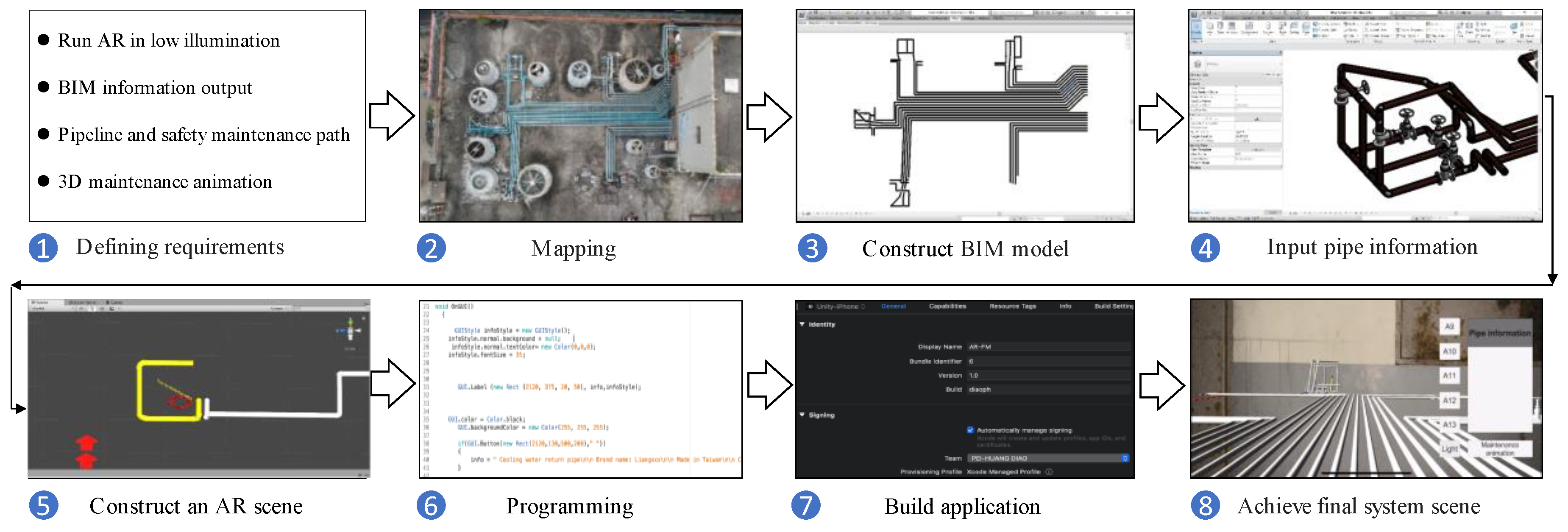
4. BARMS
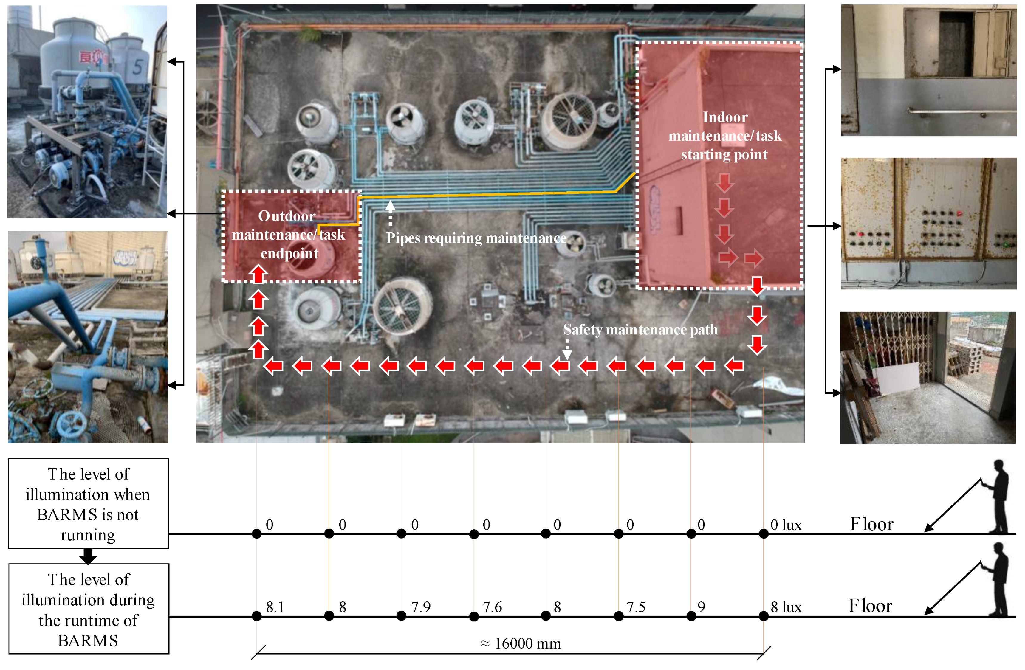
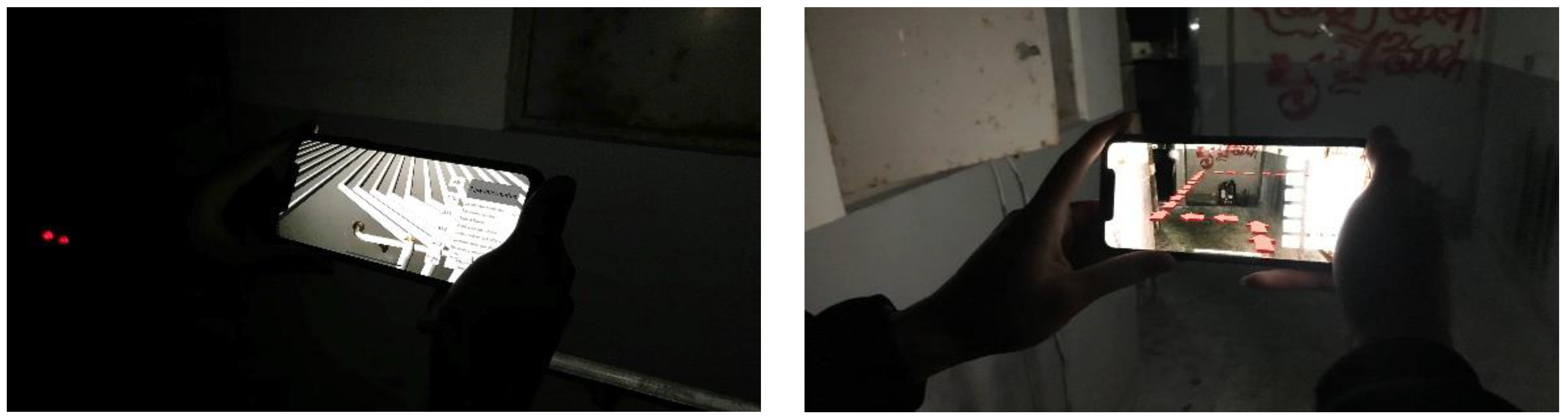
- SLAM and markerless operation in low light conditions;
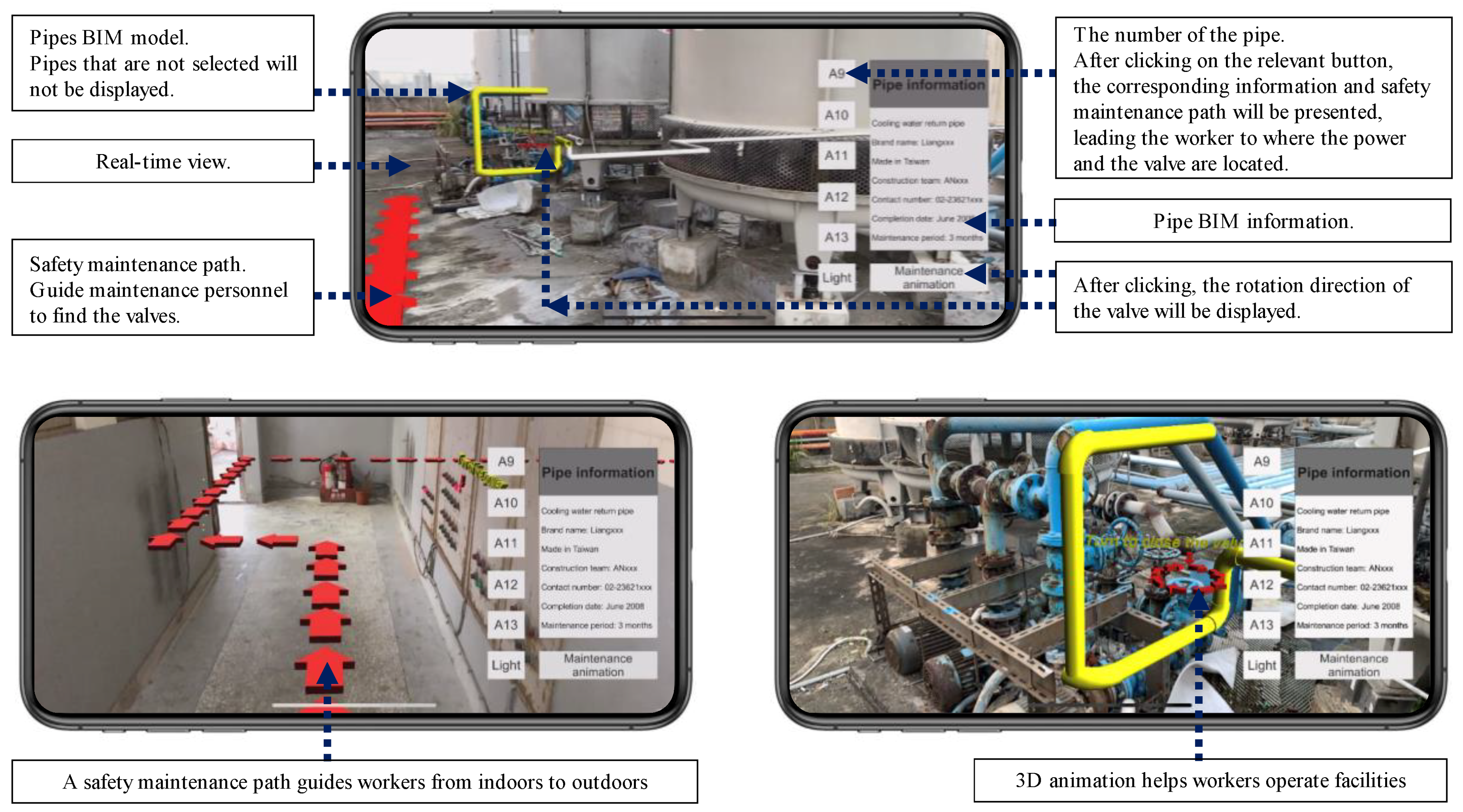
- Pipe and entity information display;
- Safety maintenance route display; and
- 3D maintenance animated guide.
5. Experiment Design
5.1. Problems Encountered in the Preliminary Tests
- Limited scope of the incorporated systems: MEP, which was separated as an individual or an isolated system, should be considered as integrated or incorporated with the whole system in order to provide a full service function;
- Searching problem: the correct power switch was not able to be located;
- Incorrect selection: a mistake was made in selecting the same pipe on either side of a wall, from indoors to outdoors, and the correct valve of the pipe was difficult to identify among a cluster of settings;
- Unknown operation sequence: no background knowledge was possessed about the inter-relationship of the shut-down sequence between the valve and the cooling tower or pump;
- Incorrect operation sequence: the valve was shut down before the pump was powered off, which resulted in idling and overheating; and
- Uncertain operation details: a trial-and-error approach was attempted to shut down the pump by rotating the valve in the incorrect direction.
5.2. Systems and Location Tested
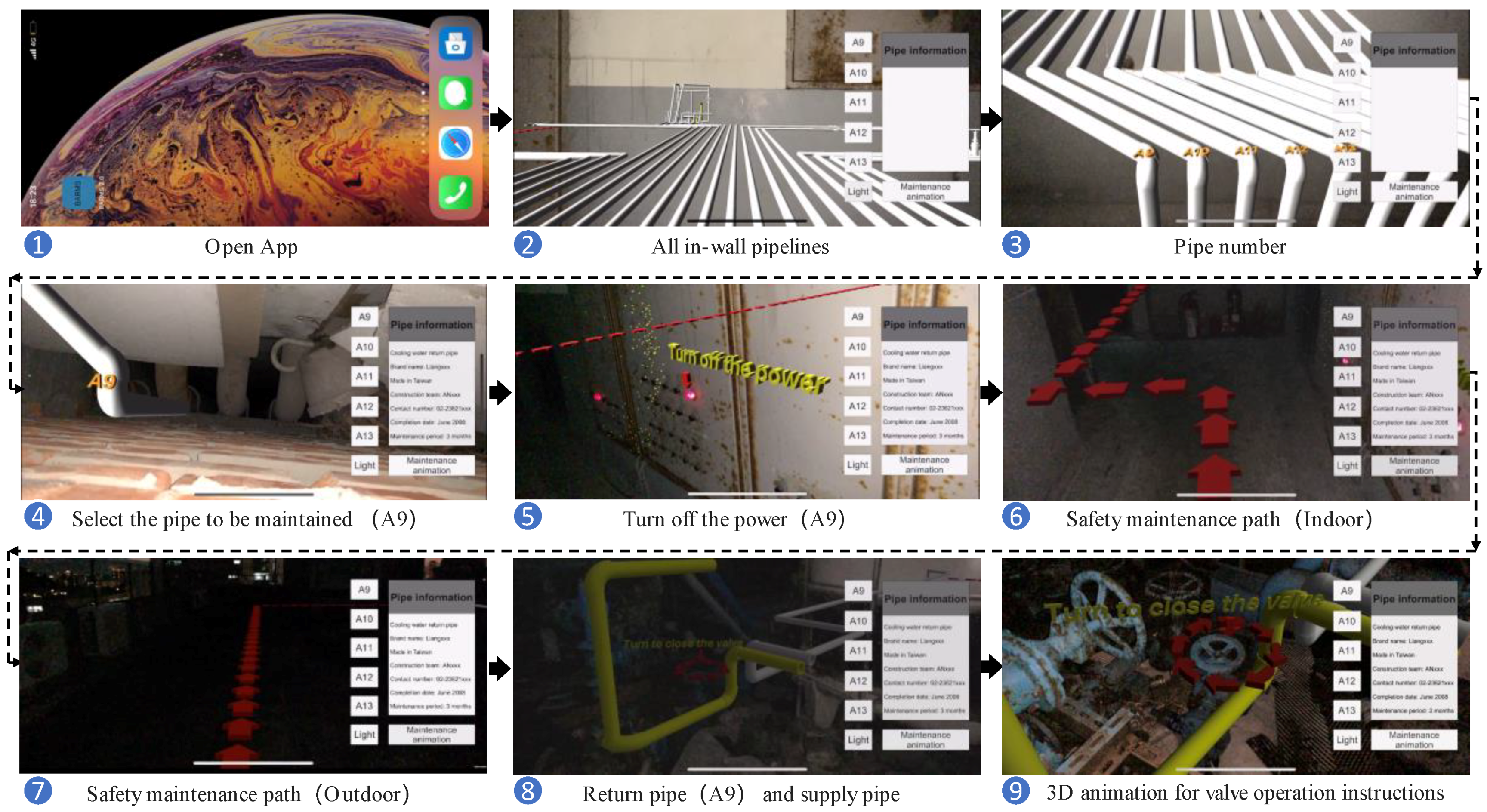
5.3. Experimental Procedures
- Retrieve leaking pipe-related information: the construction date and previous maintenance schedule were retrieved by taking advantage of existing BIM information;
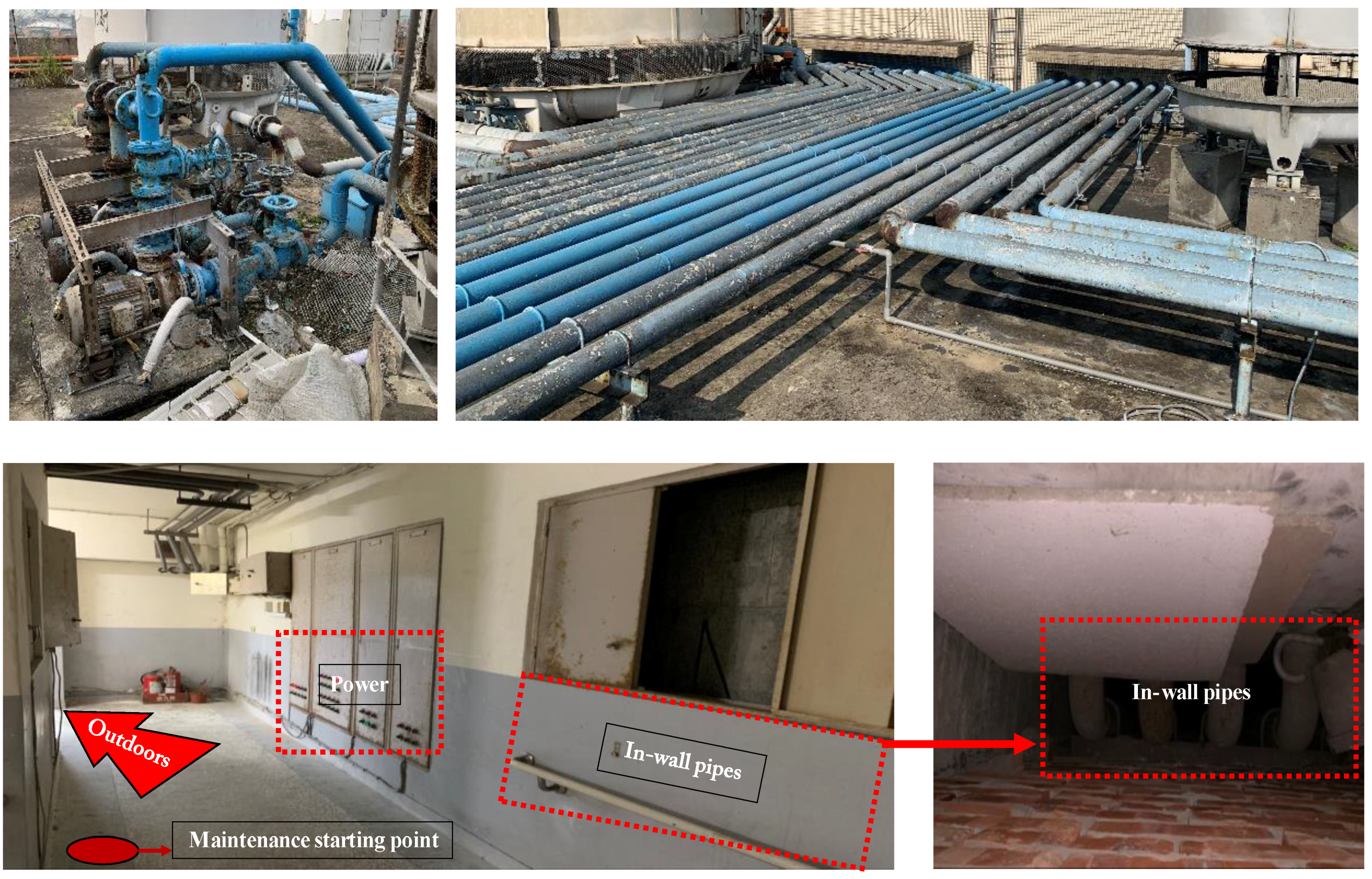
- Trace the corresponding location of the pipe on the other side of wall: tracking has to be performed among 20 possible pipes in order to identify the correct one. Not all of the 20 in-wall pipes are shown in the vertical shaft, i.e., some of the pipes are sealed in the walls. The tested pipe could be seen in the shaft relatively easier than the others. This constitutes one of the most difficult parts of the test, since the indoors and outdoors is separated by a wall, without any visual reference to the pipe outside. Counting the sequential layout of pipes is also impractical because some pipes are not visible in the shaft;
- Previous research has identified a possible solution to the pipe identification problem by projecting the outline of an entity inside of a wall to the surface in order to show the correct location when observed from the outside [11]. Our study extended this concept to show the pipe on the opposite side of a space that is not directly connected. In addition, the entity-pinpointing task had to be performed for other system components, such as the power switch of an electrical system;
- Locate the correct cooling tower to which the pipe is connected: there are two types of pipes—the cooling water supply pipe and the return pipe—which increases the complexity of accurate pipe identification;
- Shut down the power to the cooling tower and the pump connected to the return pipe: power must be shut down before the pipe or the valve. Since the system was designed using the same switch for the tower and its related pump, both components will be powered off at the same time; and
- Correctly shut down the valve connected to the return pipe.
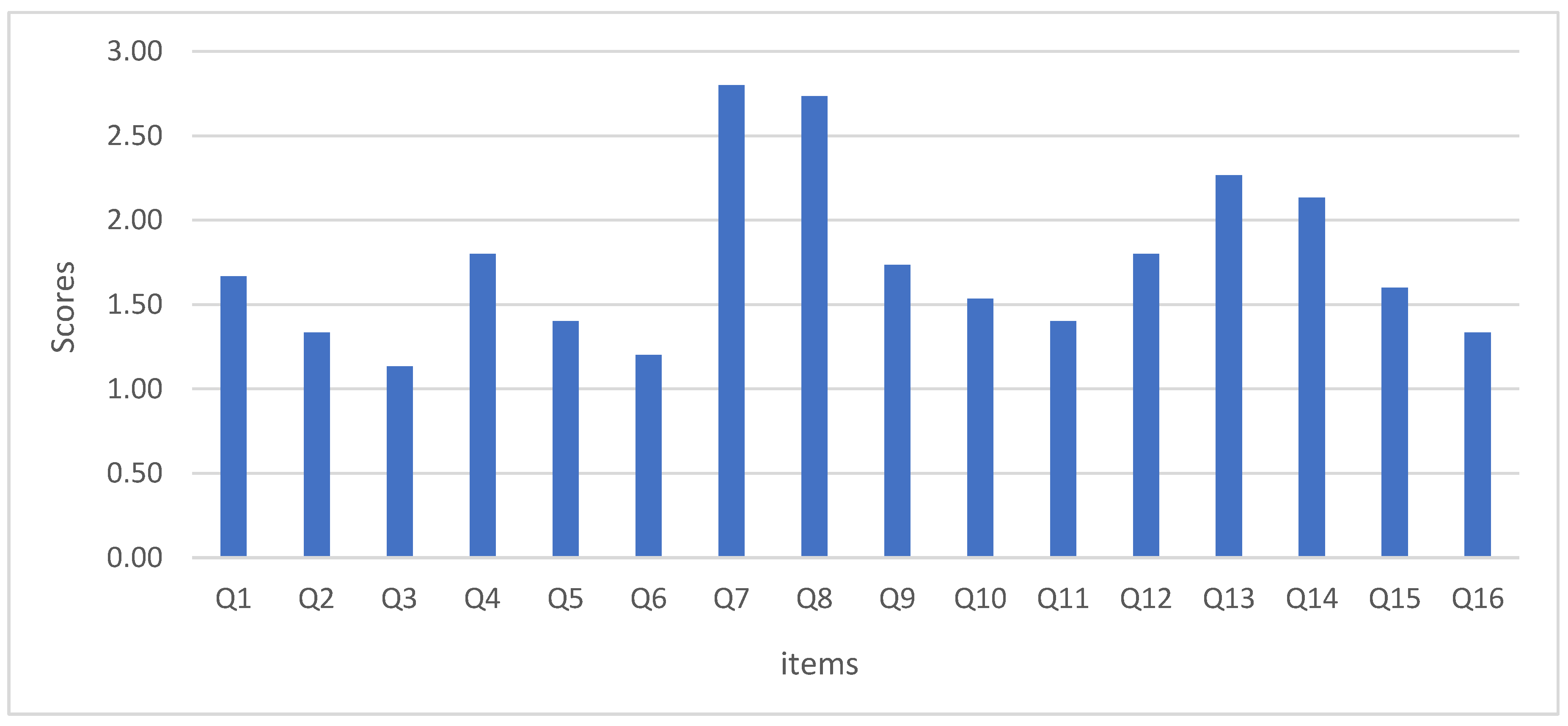
6. Experiment Result
7. Discussion
8. Conclusions
Author Contributions
Funding
Conflicts of Interest
Appendix A. Video Sample of the BARMS Testing
Appendix B. Post-Study System Usability Questionnaire (PSSUQ) for the BARMS System
- Overall, I am satisfied with how easy it is to use this system.
- It was simple to use this system.
- I was able to complete the tasks and scenarios quickly using this system.
- I felt comfortable using this system.
- It was easy to learn to use this system.
- I believe I could become productive quickly using this system.
- The system gave error messages that clearly told me how to fix problems.
- Whenever I made a mistake using the system, I could recover easily and quickly.
- The information (such as buttons, on-screen messages, and path instructions) provided with this system was clear.
- It was easy to find the information I needed.
- The information was effective in helping me complete the tasks and scenarios.
- The organization of information on the system screens was clear.
- The interface of this system was comfortable.
- I liked using the interface of this system.
- This system has all the functions and capabilities I expect it to have.
- Overall, I am satisfied with this system.
References
- Rankohi, S.; Waugh, L. Review and analysis of augmented reality literature for construction industry. Vis. Eng. 2013, 1, 1–18. [Google Scholar] [CrossRef]
- Alam, M.F.; Katsikas, S.; Beltramello, O.; Hadjiefthymiades, S. Augmented and virtual reality-based monitoring and safety system: A prototype ioT platform. J. Netw. Comput. Appl. 2017, 89, 109–119. [Google Scholar] [CrossRef]
- Neges, M.; Koch, C.; König, M.; Abramovici, M. Combining visual natural markers and IMU for improved AR based indoor navigation. Adv. Eng. Inform. 2017, 31, 18–31. [Google Scholar] [CrossRef]
- Koch, C.; Neges, M.; König, M.; Abramovici, M. Natural markers for augmented reality-based indoor navigation and facility maintenance. Autom. Constr. 2014, 48, 18–30. [Google Scholar] [CrossRef]
- Ong, S.K.; Zhu, J. A novel maintenance system for equipment serviceability improvement. CIRP Ann. 2013, 62, 39–42. [Google Scholar] [CrossRef]
- Lee, S.; Akin, Ö. Augmented reality-based computational fieldwork support for equipment operations and maintenance. Autom. Constr. 2011, 20, 338–352. [Google Scholar] [CrossRef]
- Liu, F.; Seipel, S. Precision study on augmented reality-based visual guidance for facility management tasks. Autom. Constr. 2018, 90, 79–90. [Google Scholar] [CrossRef]
- Fiorentino, M.; Uva, A.E.; Gattullo, M.; Debernardis, S.; Monno, G. Augmented reality on large screen for interactive maintenance instructions. Comput. Ind. 2014, 65, 270–278. [Google Scholar] [CrossRef]
- Park, C.S.; Lee, D.Y.; Kwon, O.S.; Wang, X. A framework for proactive construction defect management using BIM, augmented reality and ontology-based data collection template. Autom. Constr. 2013, 33, 61–71. [Google Scholar] [CrossRef]
- Chu, M.; Matthews, J.; Love, P.E.D. Integrating mobile building information modelling and augmented reality systems: An experimental study. Autom. Constr. 2018, 85, 305–316. [Google Scholar] [CrossRef]
- Irizarry, J.; Gheisari, M.; Williams, G.; Walker, B.N. InfoSPOT: A mobile Augmented Reality method for accessing building information through a situation awareness approach. Autom. Constr. 2013, 33, 11–23. [Google Scholar] [CrossRef]
- Meža, S.; Turk, Ž.; Dolenc, M. Component based engineering of a mobile bim-based augmented reality system. Autom. Constr. 2014, 42, 1–12. [Google Scholar] [CrossRef]
- Wang, X.; Truijens, M.; Hou, L.; Wang, Y.; Zhou, Y. Integrating Augmented Reality with Building Information Modeling: Onsite construction process controlling for liquefied natural gas industry. Autom. Constr. 2014, 40, 96–105. [Google Scholar] [CrossRef]
- Hou, L.; Wang, X.; Truijens, M. Using Augmented Reality to Facilitate Piping Assembly: An experiment-based evaluation. J. Comput. Civ. Eng. 2015, 29, 05014007. [Google Scholar] [CrossRef]
- Wang, X.; Love, P.E.D.; Kim, M.J.; Park, C.S.; Sing, C.P.; Hou, L. A conceptual framework for integrating building information modeling with augmented reality. Autom. Constr. 2013, 34, 37–44. [Google Scholar] [CrossRef]
- Ammari, K.E.; Hammad, A. Collaborative bim-based markerless mixed reality framework for facilities maintenance. In Proceedings of the 2014 International Conference on Computing in Civil and Building Engineering, Orlando, FL, USA, 23–25 June 2014; pp. 657–664. [Google Scholar]
- Palmarini, R.; Erkoyuncu, J.A.; Roy, R.; Torabmostaedi, H. A systematic review of augmented reality applications in maintenance. Robot. Comput.-Integr. Manuf. 2018, 49, 215–228. [Google Scholar] [CrossRef]
- Zhou, Y.; Luo, H.; Yang, Y. Implementation of augmented reality for segment displacement inspection during tunneling construction. Autom. Constr. 2017, 82, 112–121. [Google Scholar] [CrossRef]
- Kwon, O.S.; Park, C.S.; Lim, C.R. A defect management system for reinforced concrete work utilizing BIM, image-matching and augmented reality. Autom. Constr. 2014, 46, 74–81. [Google Scholar] [CrossRef]
- Diao, P.H.; Shih, N.J. MARINS: A Mobile Smartphone AR System for Pathfinding in a Dark Environment. Sensors 2018, 18, 3442. [Google Scholar] [CrossRef]
- Gerstweiler, G.; Vonach, E.; Kaufmann, H. HyMoTrack: A Mobile AR Navigation System for Complex Indoor Environments. Sensors 2016, 16, 17. [Google Scholar] [CrossRef]
- Mulloni, A.; Seichter, H.; Schmalstieg, D. Handheld augmented reality indoor navigation with activity-based instructions. In Proceedings of the 13th International Conference on Human Computer Interaction with Mobile Devices and Services, Stockholm, Sweden, 30 August–2 September 2011; pp. 211–220. [Google Scholar]
- Kalkusch, M.; Lidy, T.; Knapp, N.; Reitmayr, G.; Kaufmann, H.; Schmalstieg, D. Structured visual markers for indoor pathfinding. In Proceedings of the First IEEE International Augmented Reality Toolkit Workshop, Darmstadt, Germany, 29 September 2002; pp. 1–8. [Google Scholar]
- Mehta, D.; Siddiqui, M.F.H.; Javaid, A.Y. Facial Emotion Recognition: A Survey and Real-World User Experiences in Mixed Reality. Sensors 2018, 18, 416. [Google Scholar] [CrossRef]
- Mann, S. Wearable computing: A first step toward personal imaging. Computer 1997, 30, 25–32. [Google Scholar] [CrossRef]
- Träskbäack, M.; Haller, M. Mixed reality training application for an oil refinery: User requirements. In Proceedings of the ACM SIGGRAPH international conference on Virtual Reality continuum and its applications in industry, Singapore, 16–18 June 2004; pp. 324–327. [Google Scholar]
- Polvi, J.; Taketomi, T.; Moteki, A.; Yoshitake, T.; Fukuoka, T.; Yamamoto, G.; Sandor, C.; Kato, H. Handheld guides in inspection tasks: Augmented reality versus picture. IEEE Trans. Vis. Comput. Graph. 2018, 24, 2118–2128. [Google Scholar] [CrossRef]
- Lewis, J.R. IBM computer usability satisfaction questionnaires: Psychometric evaluation and instructions for use. Hum. Comput. Int. 1995, 7, 57–78. [Google Scholar] [CrossRef]
- Azuma, R.T. A survey of augmented reality. Presence Teleoper. Virtual Environ. 1997, 6, 355–385. [Google Scholar] [CrossRef]
- Azuma, R.; Baillot, Y.; Behringer, R.; Feiner, S.; Julier, S.; MacIntyre, B. Recent advances in augmented reality. Recent advances in augmented reality. IEEE Comput. Graph. 2001, 21, 34–47. [Google Scholar] [CrossRef]
- Carmigniani, J.; Furht, B.; Anisetti, M.; Ceravolo, P.; Damiani, E.; Ivkovic, M. Augmented reality technologies, systems and applications. Multimedia Tools Appl. 2011, 51, 341–377. [Google Scholar] [CrossRef]


| Items | N | Mean | SD | |
|---|---|---|---|---|
| Overall average | 1–16 | 15 | 1.74 | 0.40 |
| System usefulness | 1–6 | 15 | 1.42 | 0.30 |
| Information quality | 7–12 | 15 | 1.90 | 0.38 |
| Interface quality | 13–15 | 15 | 2.00 | 0.83 |
© 2019 by the authors. Licensee MDPI, Basel, Switzerland. This article is an open access article distributed under the terms and conditions of the Creative Commons Attribution (CC BY) license (http://creativecommons.org/licenses/by/4.0/).
Share and Cite
Diao, P.-H.; Shih, N.-J. BIM-Based AR Maintenance System (BARMS) as an Intelligent Instruction Platform for Complex Plumbing Facilities. Appl. Sci. 2019, 9, 1592. https://doi.org/10.3390/app9081592
Diao P-H, Shih N-J. BIM-Based AR Maintenance System (BARMS) as an Intelligent Instruction Platform for Complex Plumbing Facilities. Applied Sciences. 2019; 9(8):1592. https://doi.org/10.3390/app9081592
Chicago/Turabian StyleDiao, Pei-Huang, and Naai-Jung Shih. 2019. "BIM-Based AR Maintenance System (BARMS) as an Intelligent Instruction Platform for Complex Plumbing Facilities" Applied Sciences 9, no. 8: 1592. https://doi.org/10.3390/app9081592
APA StyleDiao, P.-H., & Shih, N.-J. (2019). BIM-Based AR Maintenance System (BARMS) as an Intelligent Instruction Platform for Complex Plumbing Facilities. Applied Sciences, 9(8), 1592. https://doi.org/10.3390/app9081592