1. Introduction
In recent years, with the rapid development of the Chinese economy and an increase in investment in infrastructure construction, all kinds of tunnel projects have been rapidly developed [
1,
2,
3,
4,
5,
6]. The increasing number of long, large and deep buried tunnels has brought great challenges to the construction and operation of projects, in which large deformation of the soft rock mass is a prominent problem [
7,
8,
9,
10,
11,
12,
13]. According to the literature reports, when complicated and difficult conditions have been encountered in tunnels, large deformation and failure phenomena have often occurred in tunnel projects including cross-section shrinkage, lining cracking, shotcrete spalling, steel arch distortion, etc. [
14,
15,
16,
17,
18,
19]. This not only damages engineering equipment, and affects the construction progress, but also seriously threatens the safety of construction personnel. Therefore, large deformation of soft rock mass has always been one of the hotspots in tunnel research [
20,
21,
22,
23,
24].
Currently, predecessors have done a lot of research work and achieved some results. Rocks containing a considerable amount of clay minerals intrude in the tunnel clearance slowly with an undetectable volume increase. This is the earliest description of large deformation of surrounding rock of Terzaghi [
25]. The concept of large deformation of soft rock was proposed by the International Society of Rock Mechanics in 1995 [
26]. It is a time-dependent deformation behavior, usually occurring around the excavation surface of underground space. It is generally caused by creep due to the instability of ultimate shear stress. This deformation may stop during excavation or last for a very long time. Tan et al. [
27] proposed that the mechanism of convergence deformation of surrounding rock should include five aspects: plastic wedge, flow deformation, swelling, dilatation, and deflection of the surrounding rock. Anagnostou [
28] proposed that large deformation mainly depends on rock strength and overburden thickness. In principle, it can occur in any type of rock mass. Singh et al. [
29] pointed out that large deformation occurs on the premise of combining weak surrounding rock with high in situ stress. Jiang et al. [
30] proposed a theoretical method for predicting the development of plastic zone and loosening pressure in soft rock tunnel and discussed the influence of mechanical properties of soft rock on loosening pressure. The causes of large deformation of soft rock mass are complex and can be generally classified into two categories: one is that the stress redistribution during excavation exceeds the strength of surrounding rock and causes plasticization; the other is that some minerals and water react and cause expansion [
31,
32,
33,
34]. On the other hand, there are also many predecessors who have done a lot of research to provide solutions to these problems in terms of assessment and treatment. Marinos [
35] obtained the design and construction of 12 tunnels driven in flysch in Northern Greece, to contribute to assessing tunnel behavior and support associated with the weak rock masses. Sun et al. [
36] proposed that the stability of the initial support system is the ultimate key to the stability of surrounding rock and support systems, using a convergence confinement method to evaluate the stability of an early support system of high-stressed soft rock. Yuan et al. [
37] formed the collaborative bearing system of surrounding rock support to a large deformation of Mesozoic soft rock, and through field tests, the validity and rationality of the collaborative bearing system were also verified.
However, up to now, due to the particularity of underground engineering, there has not been a unified understanding of the definition, classification, formation mechanism and displacement control of large deformations, which results in the theoretical research of large deformation of soft rock still lagging behind engineering applications. Therefore, it is necessary to consider the cause and development process of large deformation and put forward corresponding treatment for the smooth construction in long, large and deep buried tunnels. In this paper, rock mechanical and field monitoring tests are implemented in the construction project of a diversion tunnel of Dongsong hydropower station in Sichuan Province, China. The physical and mechanical properties of rocks are analyzed in laboratory tests. According to the monitoring data, prediction and treatment of large deformation are discussed in detail in the process of construction. The findings can provide a useful reference for theoretical basis and technical support of the construction of large deformation tunnel constructions.
2. Physical and Mechanical Test
2.1. Project Overview
The Dongsong Hydropower Station is located in Ganzi Prefecture, Sichuan Province, China, at an altitude of more than 2500 m. This paper relies on No. 2 diversion tunnel with a vertical burial depth of about 300 m, and large deformation is encountered in the construction process because of high geostress with weak and fractured rock mass. In the tunnel area, there are mainly NS (north–south) folds and faults, followed by NE and NW faults. There are 3 large-scale faults, which are the Suorang Fault (F48), Pulubiansong Fault (F48) and Xiangcheng Fault (F50). The surrounding rock is mainly phyllitic slate with a small amount of argillaceous slate and metamorphic sandstone. The lithology is extremely uneven and changes frequently. The shear fracture zone and joint are developed. The precipitation in the tunnel area is less, and the surface water is mainly supplied by the melting of alpine snow. Groundwater has the characteristics of less abundant water, large slope and deeper burial. After excavation, the surrounding rock is wet, some parts are dripping.
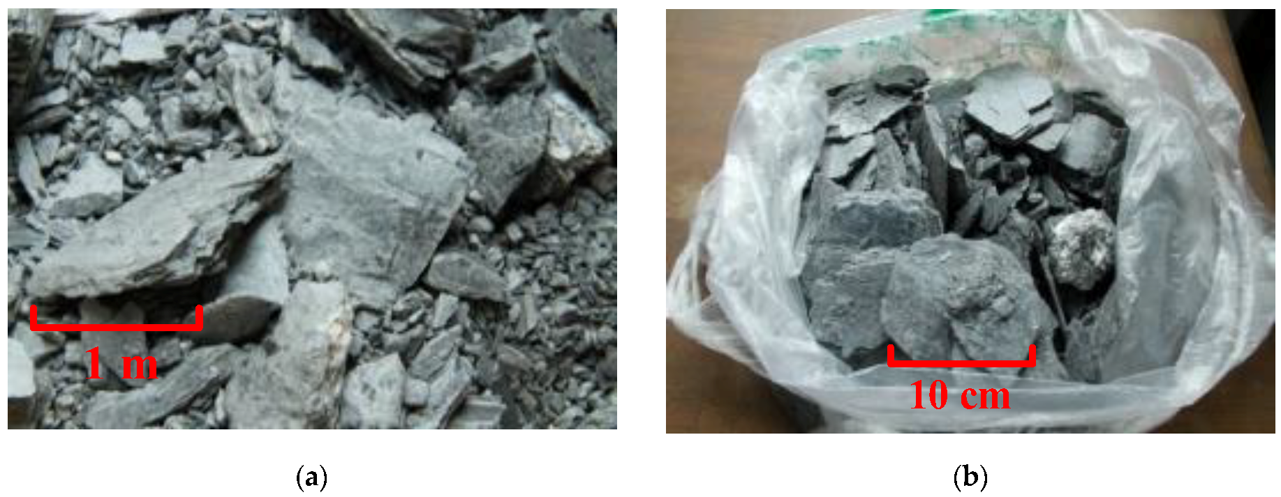
In order to gain the physical, chemical and mechanical characteristics of surrounding rock of diversion tunnel, and to provide basic parameters for the analysis of a large deformation mechanism, the optimization of tunnel excavation method, and the design and construction of the support structure, rock samples were taken from the construction site for laboratory tests (tested at the Key Laboratory of Transportation Tunnel Engineering, Ministry of Education, Southwest Jiaotong University, Chengdu, China). The test includes four aspects: mineral composition test, free expansion rate test, rock expansion pressure test, and rock mechanics test. Rock samples were taken from the site, as shown in
Figure 1. The rock samples are phyllite slate.
2.2. Mineral Composition Test
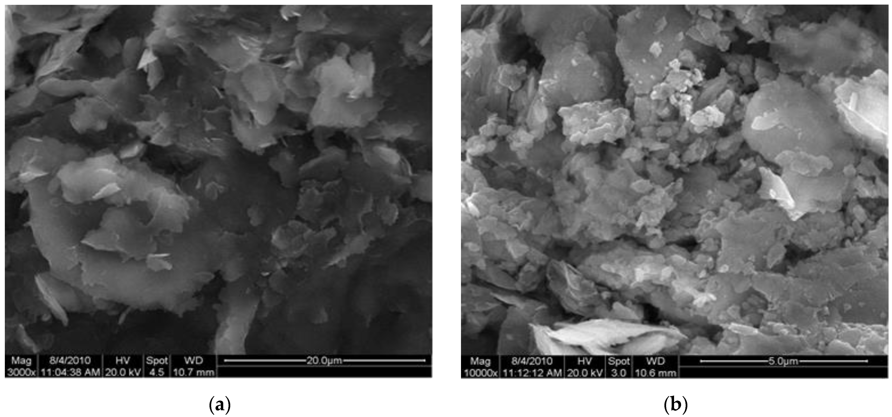
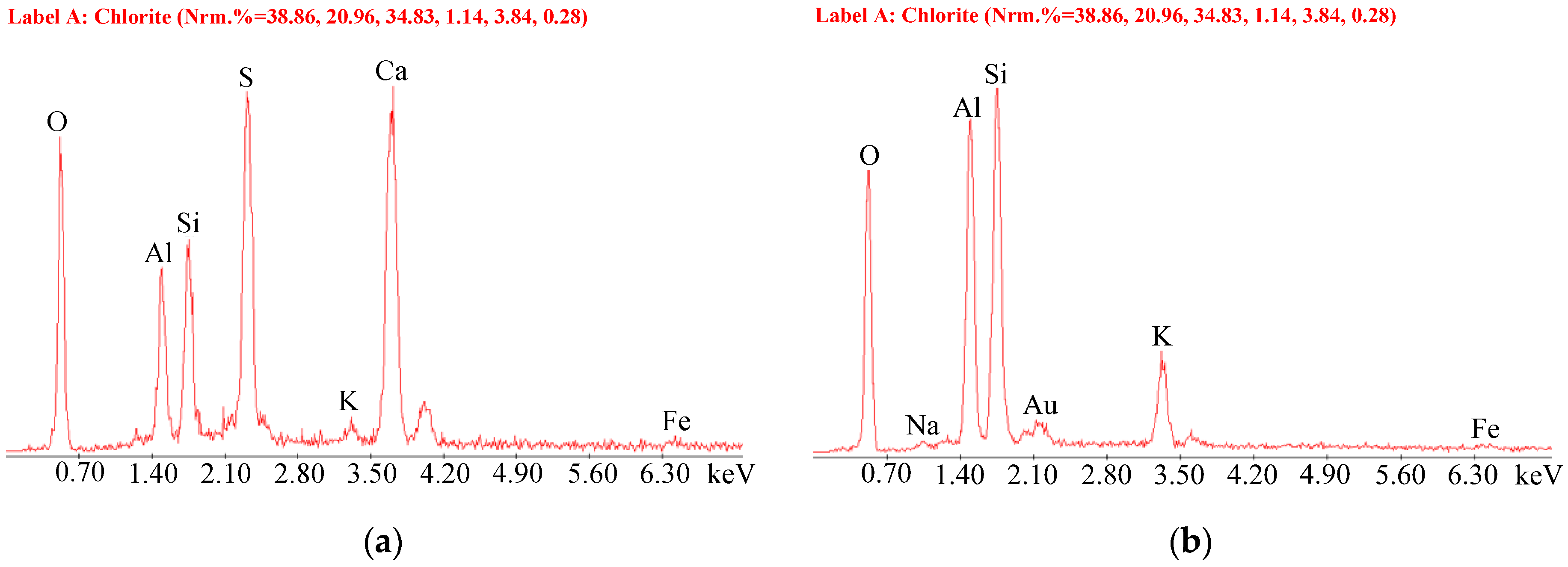
For determining the microstructure and mineral composition of rocks, scanning electron microscopy (SEM) image analysis and energy spectrum analysis of rock samples were carried out (
Figure 2 and
Figure 3). There are many flaky minerals with orientation and flaky minerals with a particle size of 2–5 microns. The main mineral components of the rocks are sericite, illite, montmorillonite, and gypsum.
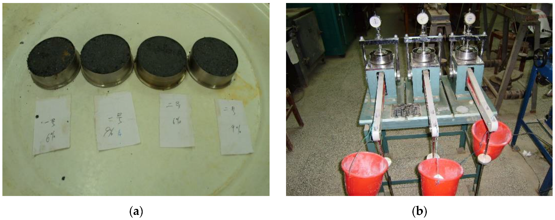
2.3. Free Expansion Rate Test and Expansion Test
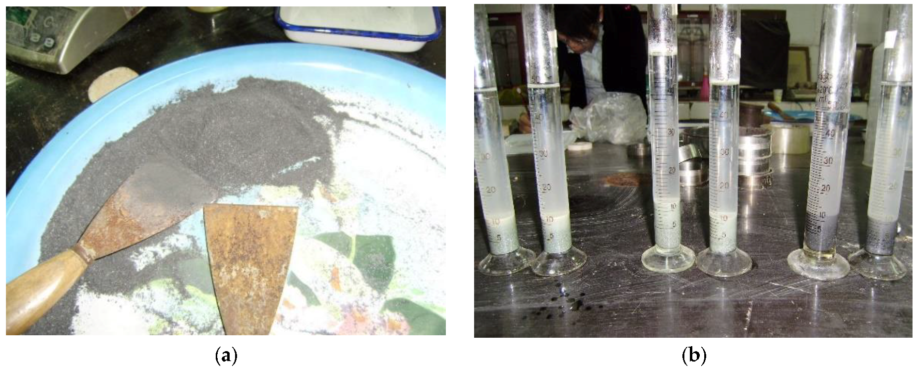
A free expanding test (
Figure 4) and expansibility test (
Figure 5) were carried out to study the expansibility of rock samples. The free expansion rate of the two caves was 20.0% and the average expansion stress was 11.0 kpa. This shows that the rock sample has low expansibility. In addition, pyrite crystals are found in the samples during the crushing process, attention should be paid to the corrosiveness of pyrite to reinforced concrete after weathering.
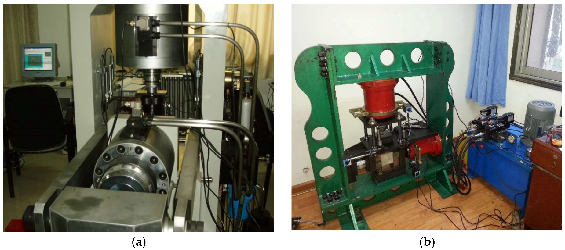
2.4. Rock Mechanics Test
The mechanical properties of rock are unconfined compressive strength and elastic modulus, which are mainly obtained by a laboratory rock test and point load test (
Figure 6). By using the standard soil test method [
38], the test results are shown in
Table 1. It is worth mentioning that the test data are based on rock tests of micro-weathering or new rock mass, and the strength obtained is relatively high. However, under the effect of weathering, water and confining pressure loss, the strength will decrease rapidly.
2.4.1. Weathering Effect
In the process of tunnel excavation, rock mass comes into contact with air, an oxidation reaction occurs, and it rapidly weathers. Compressive strength and elastic modulus of rock mass are significantly reduced [
39]. In the field, the weathered rock mass is fragmented or granular, which can be crushed by hand. Therefore, in order to avoid the rapid weathering of rocks after exposure of the tunnel face, the exposed rocks at the tunnel face and the side wall should be sealed by shotcrete immediately to minimize the contact between rocks and air.
2.4.2. Water Effect
The softening coefficient of phyllitic slate is generally about 0.3, that is, the uniaxial compressive strength of saturated slate is only 30% of that of natural intact slate. Rocks are greatly affected by water and have a strong softening effect. Rocks are easy to soften and break when immersed in water [
40]. After tunnel excavation, the surrounding pressure of the loose rock mass is low, and the strength will decrease seriously once the rock meets water. Therefore, it is crucial to control the water entering the surrounding rock. When there is water in the tunnel, we should drain the water out of the cave as soon as possible to avoid water immersion in the rock mass.
2.4.3. Confining Pressure Effect
The large deformation area is mainly phyllite slate, which is flaky soft rock. The deformation of this kind of rock has obvious strain strengthening and softening characteristics. With the increase of confining pressure, the structure of the rock sample is compacted and the compression hardening effect of elastic modulus is obvious. On the contrary, the confining pressure decreases while the elastic modulus decreases significantly. The elastic modulus is linearly correlated with the confining pressure [
41]. Meanwhile, the peak strength of rock is closely related to confining pressure. With the increase of confining pressure, the water-softening effect of peak strength decreases gradually. The softening is serious at low confining pressure but lighter at high confining pressure [
42]. Therefore, strong initial support should be applied as soon as possible to provide sufficient confining pressure in time, such as increasing the size of the steel arch and the thickness of shotcrete.
3. Field Test
3.1. Test Items and Methods
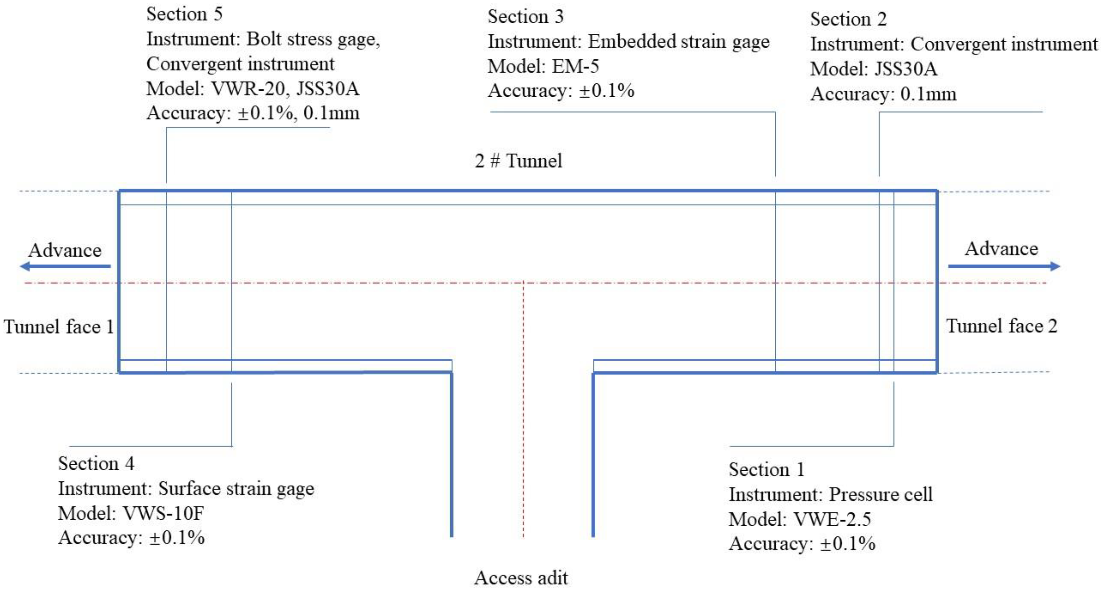
In the construction of the diversion tunnel of Dongsong Hydropower Station, serious large deformation of soft rock occurred, which had a very adverse impact on the safety and progress of tunnel construction. In order to solve this problem, besides the physical and mechanical properties of rock, it is necessary to master the deformation and stress law of rock mass and the supporting structure. Therefore, a lot of field test work has been carried out in the 2# tunnel under construction.
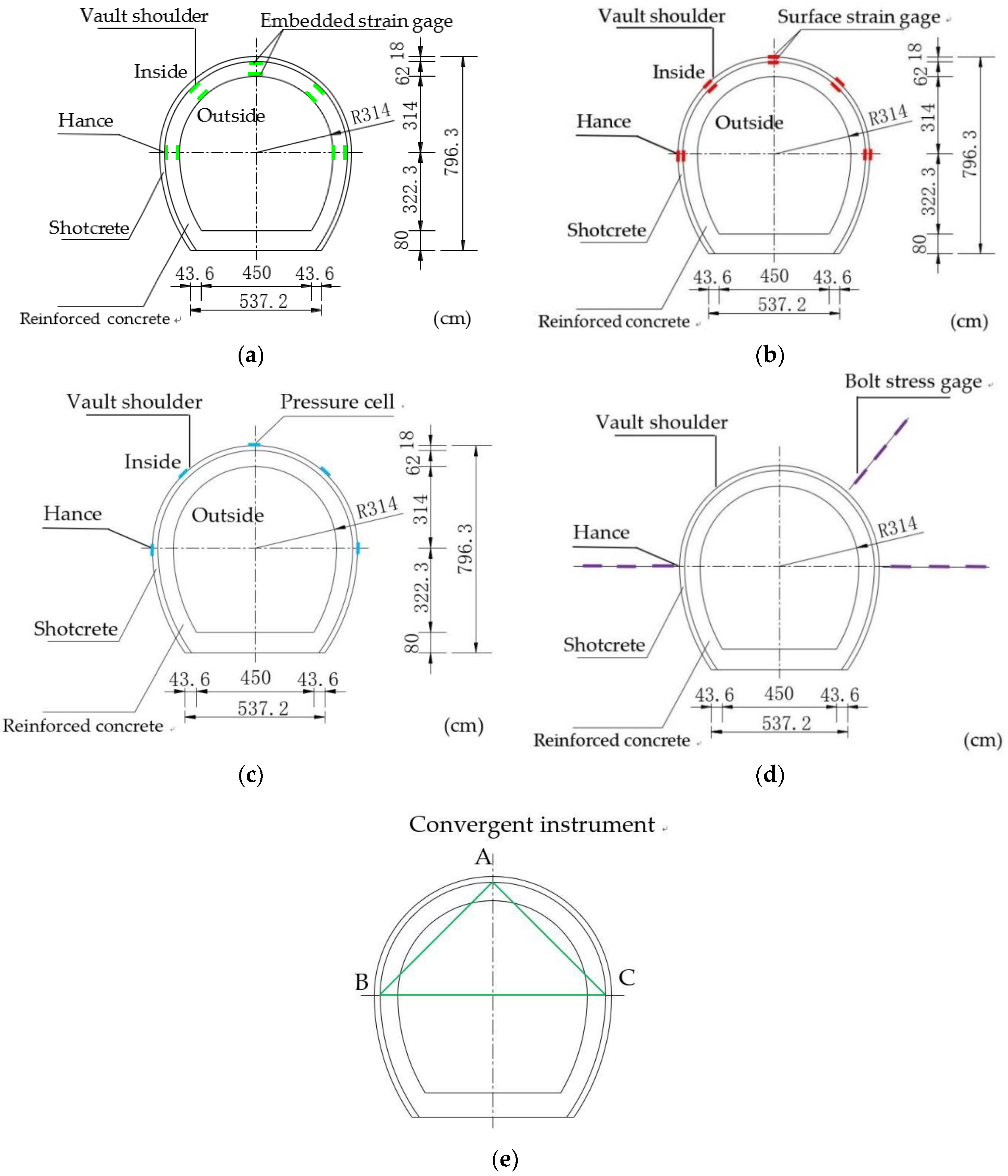
The test items include a stress test of the supporting structure (tunneling by drilling and blasting method, C25 shotcrete, Φ22 rock bolt with 5 m length, I20A steel arch, the second lining of C40 molding concrete), a contact pressure test between rock mass and initial support, and tunnel clearance deformation monitoring. The distribution position of the monitoring section in the tunnel is shown in
Figure 7; the instrument arrangement positions on the monitoring section are shown in
Figure 8; the test items and methods are shown in
Table 2.
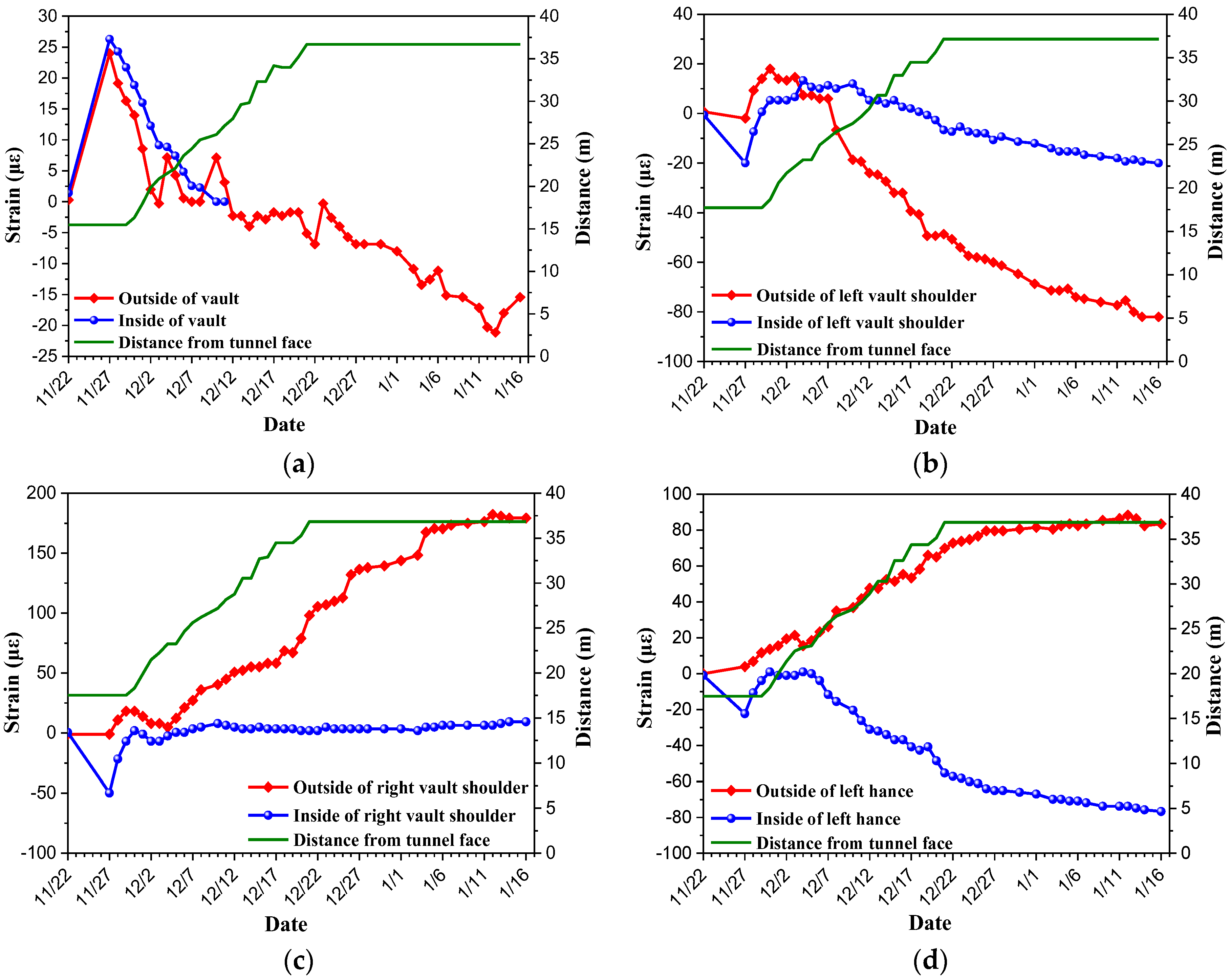
3.2. Second Lining Strain
Monitoring results of the second lining strain in
Section 3 are shown in
Figure 9 (the monitoring element was damaged during construction, partial data of vault inside were missing). In this section, large deformation occurred shortly after the tunnel excavation, which led to the initial support intruding into the clearance, and the second lining had to be constructed after the secondary expanding excavation.
As can be seen from
Figure 9, most parts are in a compressive state, and the strain is between 20 to 200 με. At a few parts, tension strain exists, and the maximum tensile strain is 175 με, which are far less than the ultimate strain of concrete (about 2000 με), in the safe range. No cracking of concrete is found in field observations. The surrounding rock is relatively stable after secondary expanding excavation. The strain of concrete is closely related to the construction of the tunnel face. When the tunnel faces advanced, the strain kept a stable deformation rate and develops steadily. Once the tunnel face stops, the strain tends to converge. After losing confining pressure, the surrounding rock softens and relaxes for a relatively long time. After increasing confining pressure by lining, the strain tends to converge and the expansibility of the surrounding rock is not strong, which is consistent with the laboratory test results.
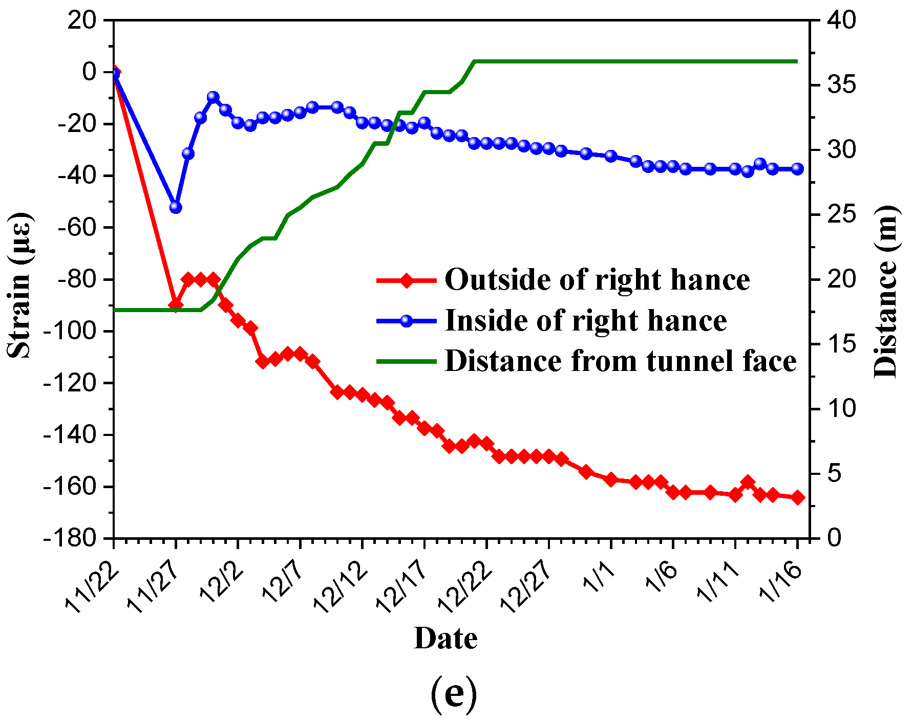
3.3. Steel Arch Stress
The stress of the steel arch converted from the strain obtained by monitoring is shown in
Figure 10 (the monitoring element fell off during construction, and the data of right hance inside were invalid). The steel arch is subjected to compression mainly and tension partly. The maximum tensile stress was 70 MPa and the maximum compressive stress was 40 MPa, which are less than the tensile and compressive strength of the steel arch respectively. The influence of excavation on the stress of the steel arch is not obvious after the tunnel face is closed for a period of time. This is because the stress of the steel arch converges rapidly and the confining pressure is not lost. The direction of large stress is vertical, but the direction of large strain obtained in the previous section was horizontal. This phenomenon indicates that inconsistency between the direction of large stress and the direction of large strain may be due to the dilatancy effect [
43]. The lithology is extremely uneven and changes frequently. The shear fracture zone and joint are developed. Based on these, under the effect of high vertical stress, the dilatancy occurs in the direction of small stress, thus the horizontal strain is much larger.
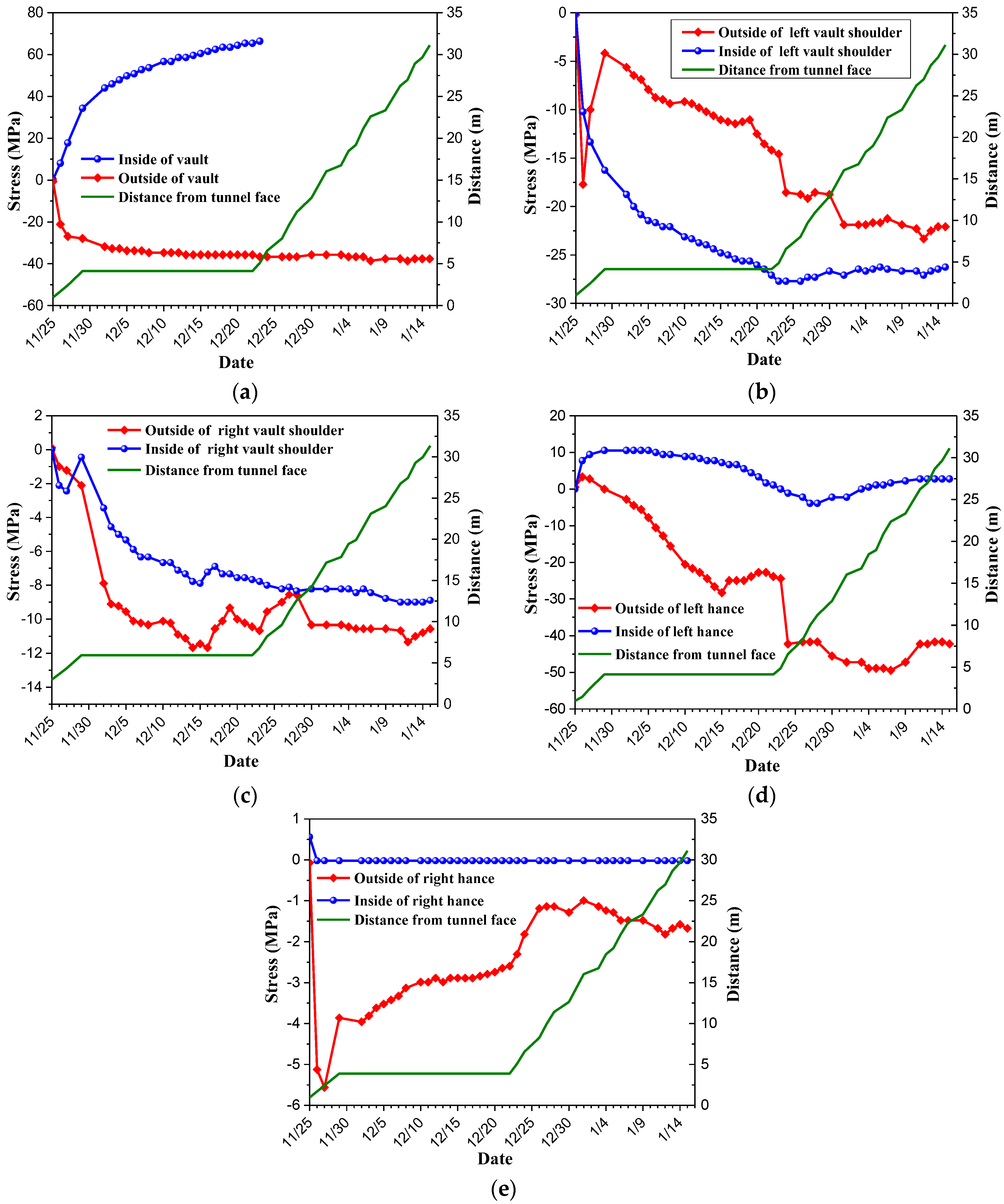
3.4. Contact Pressure Between Rock Mass and Initial Support
As we can see from
Figure 11 (the sensor was damaged during construction, and left hance data and partial vault data were missing), the maximum contact pressure at the vault shoulder was about 0.9 MPa, which exceeds the ultimate load that the steel arch can bear. Field observation also shows that the steel arch was damaged, deformed and distorted, and the shotcrete cracked and peeled (
Figure 12). The monitoring results are consistent with the field observation results. The contact pressure did not develop until the tunnel face ceased to be excavated and was sealed. The large deformation of surrounding rock is mainly caused by the advancing of the tunnel face. When large deformation occurs, the advance of a tunnel face should be stopped. The large deformation has exceeded the bearing capacity of the initial support. The second lining should be applied in time to control the rheological deformation of the surrounding rock in the later period.
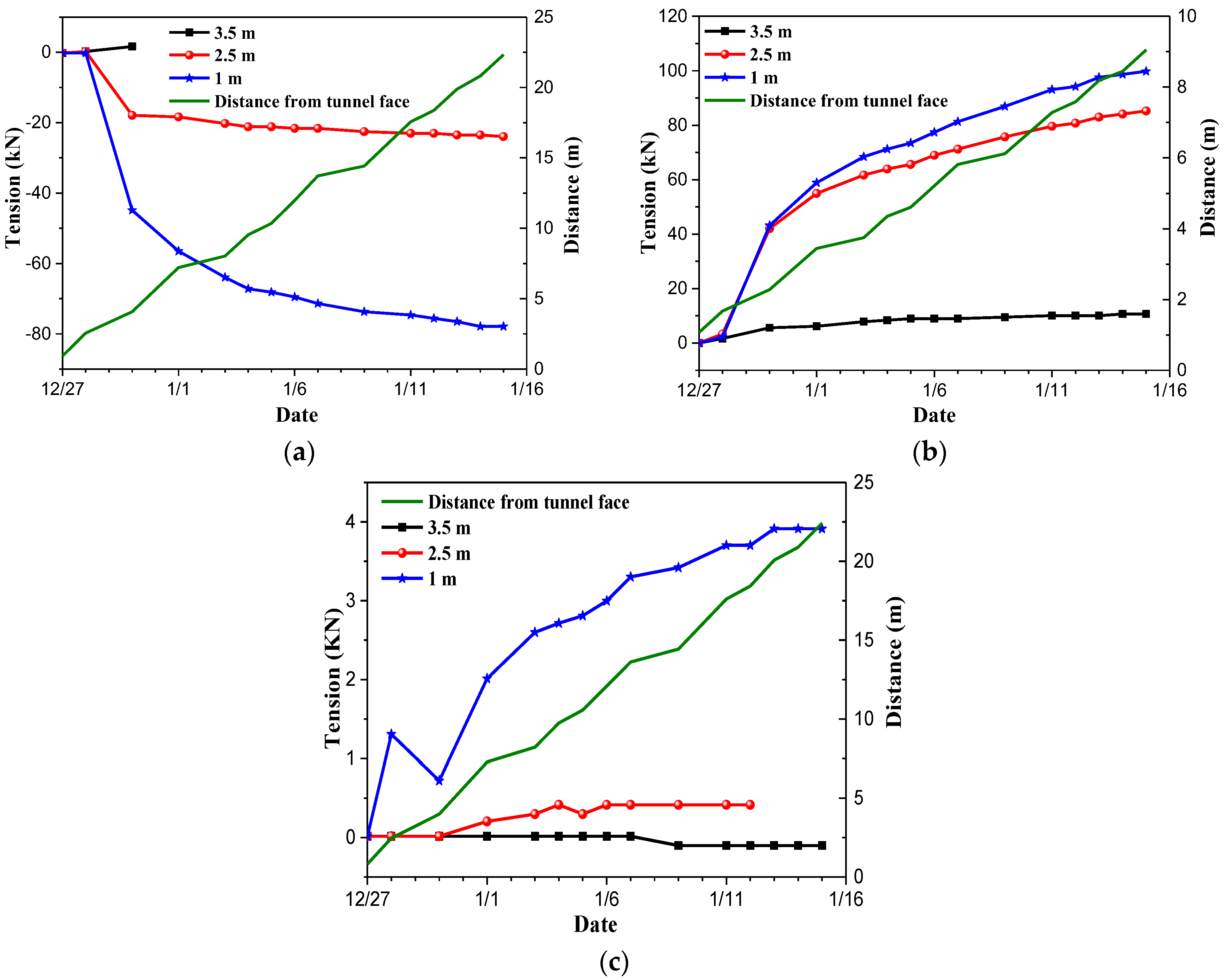
3.5. Bolt Force
From
Figure 13 (the monitoring element was damaged during construction, and partial data of right vault shoulder were missing), we can find that some monitoring results of the same section or even the same bolt are quite different, which is due to the poor grouting quality of constructed bolts. The monitoring of bolt stress is greatly affected by the construction quality. The quality of bolt construction is very important to the effect of the bolt, which should be guaranteed. Compared with other monitoring projects, the monitoring accuracy of bolt stress is susceptible to interference and difficult to guarantee, so other monitoring projects should be adopted as far as possible.
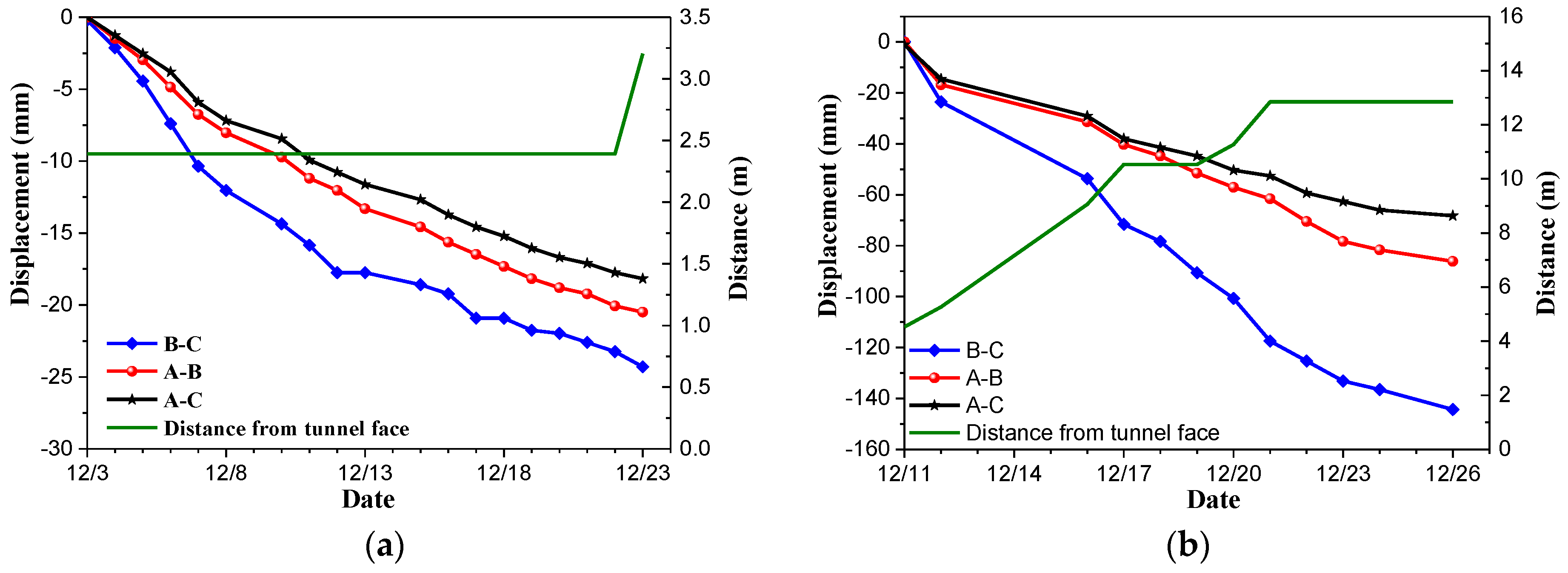
3.6. Clearance Convergence Deformation
At both sections, the monitoring work continued until the construction of the second lining. It can be seen from
Figure 14a that the maximum horizontal convergence was about 25 mm, and the average daily deformation value was about 1 mm. And no initial support wreck is found by field observation. As we can see from
Figure 14b, the maximum horizontal convergence was about 140 mm, the average daily deformation value was about 10 mm, which is consistent with monitoring results of contact pressure between rock mass and initial support and field observation (the steel arch has been damaged, deformed and distorted, and the shotcrete has cracked and peeled).
4. Discussion
Based on the same engineering background, we have studied large deformation of soft rock tunnel by theoretical analysis and numerical simulation in our published papers and expressed corresponding views, such as stress field distribution and deformation law [
44]. In this paper, based on the further analysis of monitoring data, new progress has been made. Many previous researchers put forward opinions on the irregular behavior of large deformation tunnel support. For example, Zbigniew et al. [
45] based on the Laliki tunnel in the Carpathian flysch pointed out that the expansive claystone content and steep dip of the strata are critical in this aspect, because they both lead to the shear displacements. However, based on the field observation in this paper, the dip of the strata is not steep, the rock is not expansive claystone and the expansibility of the rock is low, and hence it is not a common large expansive deformation. The large deformation of surrounding rock mainly comes from the dilatancy effect with high geostress and relaxation deformation with weak support. A month or two may be not long for the entire monitoring process, but the dilatancy effect with high geostress and relaxation deformation have been basically completed during this period, and later data will be used for follow-up research into the creep model.
5. Conclusions
Large deformation of soft rock is a prominent problem during the construction of underground engineering. This paper analyzed the specific cause and deformation law, discussed in detail the prediction and treatment of large deformation by physical and mechanical tests and a field-monitoring test. The following conclusions are drawn:
(1) There are many flaky minerals in phyllite slate, and the size of flaky minerals is 2–5 microns, which has directionality and can cause anisotropic characteristics of the rock. When pyrite-bearing crystals are found during the sample grinding, attention should be paid to the corrosiveness of pyrite to reinforced concrete after weathering. According to the laboratory test, the free expansion rate of the rock sample is 20.0%, the average expansion stress of the rock sample is 11.0 kpa, and the expansibility of the rock is low. Unlike the common expansive large deformation, the large deformation in this paper mainly comes from the dilatancy effect with high geostress and relaxation deformation with weak support and is closely related to fragmentation and strength.
(2) In order to avoid the low strength of surrounding rock, measures should be taken in time to deal with the three main factors (weathering, water and confining pressure) that affect the strength of surrounding rocks. For example, after excavation, shotcrete should be sprayed to expose surrounding rock to avoid continuous contact between surrounding rock and air; Early strength support and a second lining should be applied to provide confining pressure for the surrounding rock, to control the loss of confining pressure or to restore a certain confining pressure; and to try to control the water entering the surrounding rock. When there is water in the tunnel, the water should be drained out of the tunnel as soon as possible to avoid water immersion in surrounding rocks, etc.
(3) Generally, the bolt must be penetrated into the elastic zone at least 1/3 of the length of the bolt to achieve better results. However, due to the small section of the tunnel, bolts need to be lengthened several times to form long bolts, and long boreholes are easy to collapse, which is very disadvantageous to the construction period. Short bolts are used to fix the steel arch on the surrounding rock horizontally and increase the number of bolts to effectively control the occurrence of large deformation in the soft rock mass.
(4) The monitoring data show that the results of other monitoring items are in good agreement with the field observation, and can reflect the deformation of surrounding rock and the stress state of supporting structure more accurately, except for the unsatisfactory monitoring results of bolt stress. That is because of the poor grouting quality of constructed bolts. The monitoring of bolt stress is greatly affected by the construction quality. The quality of bolt construction is very important to the effect of the bolt, which should be guaranteed. Compared with other monitoring projects, the monitoring accuracy of bolt stress is susceptible to interference and is difficult to guarantee, so other monitoring projects should be adopted as far as possible. In particular, clearance convergence has the advantages of intuitive results, easy quality assurance of instrument installation and high accuracy. It is suggested that clearance convergence should be the main monitoring work in construction.
(5) For the support of soft rock, the pressure cannot be relieved excessively. Soft support first and hard support afterward are more reasonable. A second lining should be used to control the deformation in time after the initial support is stable. Otherwise, the rheological deformation of soft rock in the later stage will increase the stress of the initial support and cause instability and failure. The monitoring results show that the stress of reinforcement and concrete is smaller after the second lining is applied in time, which indicates that the surrounding rock is provided with high confining pressure after the second lining is applied, the relaxation of surrounding rock is controlled, and the cracking and large deformation of concrete are not identified in the field observation.


