Review

Review of VSG Control-Enabled Universal Compatibility Architecture for Future Power Systems with High-Penetration Renewable Generation

Key Laboratory of Distributed Energy Storage and Micro-Grid of Hebei Province, North China Electric Power University, Baoding 071000, Hebei Province, China
*
Authors to whom correspondence should be addressed.
Appl. Sci. 2019, 9(7), 1484; https://doi.org/10.3390/app9071484
Submission received: 28 February 2019 / Revised: 16 March 2019 / Accepted: 26 March 2019 / Published: 9 April 2019
(This article belongs to the Special Issue Emerging Power Electronics Technologies)

Abstract

:
Due to the irreversible energy substitution from fossil fuels to clean energy, the development trend of future power systems is based on renewable energy generation. However, due to the incompatibility of converter-based non-dispatchable renewable energy generation, the stability and reliability of traditional power systems deteriorate as more renewables are introduced. Since conventional power systems are dominated by synchronous machines (SM), it is natural to utilize a virtual synchronous generator (VSG) control strategy that intimates SM characteristics on integrated converters. The VSG algorithm developed in this paper originates from mimicking mathematic models of synchronous machines. Among the different models of implementation, the second-order model is simple, stable, and compatible with the control schemes of current converters in traditional power systems. The VSG control strategy is thoroughly researched and case studied for various converter-interfaced systems that include renewable generation, energy storage, electric vehicles (EV), and other energy demands. VSG-based integration converters can provide grid services such as spinning reserves and inertia emulation to the upper grids of centralized plants, distributed generation networks, and microgrids. Thus, the VSG control strategy has paved a feasible way for an evolutionary transition to a power electronics-based future power grid. By referring to the knowledge of traditional grids, a hierarchical system of operations can be established. Finally, generation and loads can be united in universal compatibility architecture under consolidated synchronous mechanisms.

1. Introduction

Renewable energy, such as photovoltaic and wind energy, has been widely developed and utilized in power systems during the past few decades, which has been prompted by the urge to tackle environment crises and sustain economic development [1]. According to the 2018 BP energy outlook, more sustained support for renewables will be largely phased out by the mid-2020s, leading to a strong growth in the share of renewables reaching 25% of total energy consumption in an evolving transition scenario by 2040 [2]. The integration of renewable energy generation is also one of the central demands of any future smart grid, yet there are still many issues and challenges. Regarding the characteristics of their generation profiles, renewable energies such as wind and photovoltaic vary largely when compared to conventional generation such as coal and nuclear. The output of wind turbines and solar panels fluctuate with random and intermittent meteorological conditions, while conventional power plants can be regulated precisely and continuously. Moreover, wind and solar generators, which are integrated by power converter interfaces with almost zero inertia characteristics, cannot provide spinning reserves to the system [3]. As fossil energy depletes, renewables will eventually take the place of traditional power sources, while high-penetration renewable energy generation would severely degrade the reliability and stability of such traditional power system.
Many studies have been published that address the issues of renewable energy generation integration. In [4], the classification of power converters in alternating current (AC) microgrids is proposed, in which converters are generally divided into three functional categories as grid-forming, grid-feeding, and grid-supporting. However, the functional conversion of power converters is constrained by the current state of renewables; as a result, the faults of key converters may cause entire systems to break down. Such concerns also exist in multilayer architectures such as master–slave structures in which converters are parallel operated in such a way that allows only a few key converters to regulate the whole system [5]. In [6], communication and information technologies were harnessed for renewables in both demand–response and energy storage units. Such a grid-wide information technology (IT) architectural framework enhances the maneuverability, efficiency, and resiliency. However, the entire grid could fall if the communication network fails or a cyber-attack happens. Also, the management of IT infrastructures for distribution networks with a huge quantity of renewable distributed generations (DGs) and micro grids (MGs) involves further issues. In [7], the planning of renewable energy generation considers mainly the whole life cycle cost with maximum energy extraction, which seems to be irresponsible for the upper grid, as the regulation cost and efficiency of reserved conventional generation are left out of consideration. In [8], in the operational scheduling for power systems with renewable power plants, only the participation of conventional sources (coal and pumped storage plants) is considered. The scheduling would be better if it feasibly took the participation of renewables into account. In [9], the load management strategy and autonomous demand-side response in smart buildings were illustrated. However, the load was maneuvered by the power access control in on–off mode.
Note that the key point of the evolving transition from conventional energy to renewables involves coordinating heterogeneous renewable energy generation into the present power system, which is dominated by synchronous machines, and maintaining system reliability and stability. Thus, finding the most economic and compatible way to integrate renewable energy generation is the most evolutionary way for future power systems. The VSG control strategy utilizes the flexible controllability of converters to mimic the behavior of traditional synchronous machines [10,11,12,13]. By implementing a VSG control strategy, renewable power plants or DGs can provide system services such as inertia emulation, oscillation damping, and voltage support. In doing so, conventional SM and renewable energy are unified under the same synchronization mechanism and jointly participate in the regulation of system stability and overall energy balance. Furthermore, as the parameters of VSG controlled converters are not fixed but rather tunable without physical limitations, the virtual inertia, damping factor, excitation inductance, and mutual inductance can be designed according to the properties of the integrated network [14]. VSM technology has great prospects in future power systems. It can be used as a low-level control strategy that utilizes autonomous control for the converter-based apparatus, while the communication and information network can be implemented for upper-level control. By utilizing the regulation capability that the VSG enables, the operation center can focus on global system monitoring, scheduling, and dispatch for optimal operation and the electric market [15]. This paper reviews the VSG control-enabled universal compatibility architecture for future power systems with high-penetration renewable energy generation. Section 2 contains traditional operation knowledge and the technical gap for smart grid integration. In Section 3, a mathematical model and the synchronization mechanism of synchronous machines are illustrated for VSG modeling. Then, the applications of the VSM algorithm—wind turbines, photovoltaic, energy storage, electrical vehicles, and demand-side response—are introduced in Section 4. In Section 5, the grid service provided by VSG-based renewable DGs and the microgrid in the transmission and distribution network is introduced. At last, for evolving transition into a power electronic-based future smart grid, the integration of high-penetration renewable energy generation into the current power system under a VSG-enabled universal compatibility architecture is proposed in Section 6.

2. Outlook for Smart Grid Integration

2.1. The Challenges of a Conventional Power System

The current AC power grid has been dominated by synchronous generators for over 100 years. The system architecture is hierarchical, which is composed of four parts: generation, transmission, distribution, and consumption, with unidirectional power transmission. In the power system, a set of generators in parallel regulate the system’s stability and global energy balance. In this way, the system reliability is also protected against failure or the scheduled maintenance of one generator or part of the grid. When the optimal operation point of the synchronous generator is near its full load, a system operation schedule is created. Due to the large kinetic energy stored in rotors, synchronous generators have large inertia and a slow response, which benefits the grid in the transient process.
However, due to the increasing penetration of power electronic-based renewables and other units, power systems has been through intrinsic changes. In terms of energy sources, the irreversible transition from fossil energy to renewable energy has deeply changed the power system. Part of renewable energy generation is centralized through renewable power plants in remote areas, such as hydro plants, wind farms, or solar plants. More renewables have been introduced as DGs and microgrids have been integrated into distribution networks to enhance the reliability and power quality, as well as pursue profits for the owners. Due to the low-energy density of renewables, the quantity of integrated DGs needs to be large in comparison to traditional power systems.
Hence, the topology of the distribution network has been greatly changed. First, the morphology of the power system has been transformed from centralized generation with relatively few major power plants to a system that is highly decentralized and distributed. From the view of the dispatching center, it is sometimes difficult to regulate the specific node that regulates the self-governed renewables, which has a local impact. Second, renewable energy—together with the energy storage or generation backup established in the form of pumped storage power plants, electric vehicles, and advanced energy storage devices—converts power transmission direction from unidirectional to bidirectional or multidirectional. Moreover, the interfaces of renewables, energy storage, electric vehicles, AC adjustment, and direct current (DC) consuming loads are commonly converter-based. As a result, future power systems will be electronic-based, rather than based on electrical machines [3]. As the energy conversion interfaces in power systems evolve from magnetic fields between rotors and stators to high-frequency power-switching devices, future power systems based on electronic converters benefit from more flexibility, controllability, and a faster response. At the same time, the system inertia also decreases significantly.
At the power system level, when renewable penetration is relatively low, the system stability and overall energy balance can be regulated through spinning reserves, which compensates for generation disturbance and frequency fluctuation. However, if the penetration reaches a certain level, the system stability is severely degraded. In the distribution network, the challenge of renewable integration is more complex, due to the large quantity of renewable units with different profiles. Data acquisition and supervisory control are also needed for optimal operation and resilient control [3]. The efficient coordinative regulation of massive DGs and analytical methods of computing and utilizing a massive amount of data for performance enhancement challenge the distribution network.

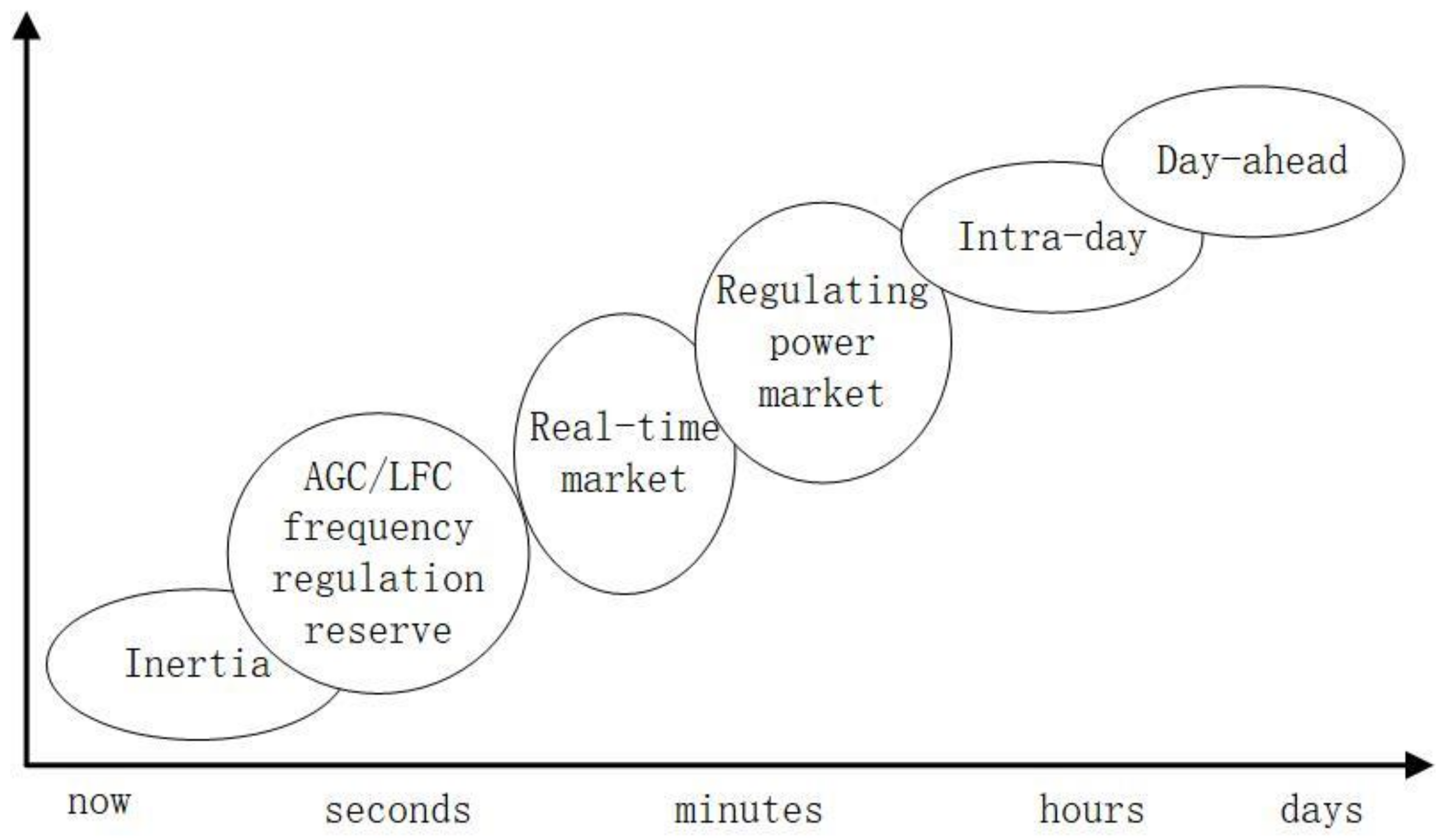
2.2. Knowledge of Power System Operation

The central function of power grids is to transport real power to feed loads. To achieve that, strong, stable, and reliable power systems should be built on a foundation that consists of equipment and grid services. Traditional power plants are equipped with synchronous generators (SG) to extract high-density bulk energy (coal, hydro, nuclear) for electricity. SG, as independent voltage sources, can either feed isolated loads or easily be integrated into groups that form a more reliable power grid through their distributed management of the grid. When the generator is operating, large kinetic power is stored in machine rotors while reactive and harmonic currents are fed through stator impedance. The droop characteristics of SG possess and stabilize the dynamic electro–magnetic–mechanical energy conversion through regulating and coordinating the output power according to the rated frequencies and voltage. According to the operation status and load profile, transformer taps can be modified to raise/lower the voltage of a specific feed line to change its power flow. Capacitor banks are commonly used to supply reactive power and eject harmonic currents to enhance voltage regulation, power quality, and reduce network losses. System-level grid services then are able to enhance the stability, reliability and economic efficiency of the equipment in both steady and transient states. Power/demand forecasting, which is the foundation of this high-level system operation, includes optimizing both mid-term and long-term operation through scheduling, dispatching, and marketing. The operation of a traditional power system is shown is Figure 1 on a time-scale.

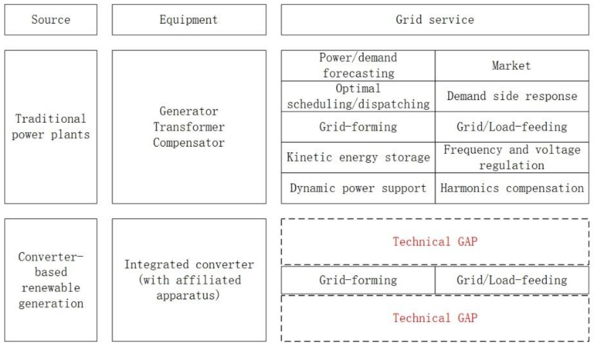
2.3. Technical Gap for VSG

Most converter-based renewable energy generation has almost zero inertia, as photovoltaic (PV) has no spinning components, and the kinetic energy of wind turbine (WT) blades is often minimized by the control strategy of a back-to-back converter. The energy is intermittent, non-dispatchable, and needs adequate balancing resources to maintain safe operation against transients, fluctuations, and contingencies. As a result, the key problem of high-penetration renewable energy generation is not only energy source substitution, but also providing grid service in both steady and transient states. Although the conventional architecture of traditional power systems is not designed for distributed and decentralized generation, synchronous generators do not have this problem. As a result, even though there are challenges regarding the integration of decentralized renewable energy sources, their operation theories and architecture also have advantages over traditional power systems. At the same time, the advanced knowledge system that governs the current power grid can be applied to the new renewable energy sources. For example, the VSG control inherits the advantages of both flexible converters and the properties of synchronous machines. Thus, regarding the existing knowledge of traditional system operations, the present technical gap for the VSG algorithm is ensuring that its converters contribute a similar grid service as that of the synchronous machines, as shown in Figure 2.

3. Modeling the VSG Control Strategy

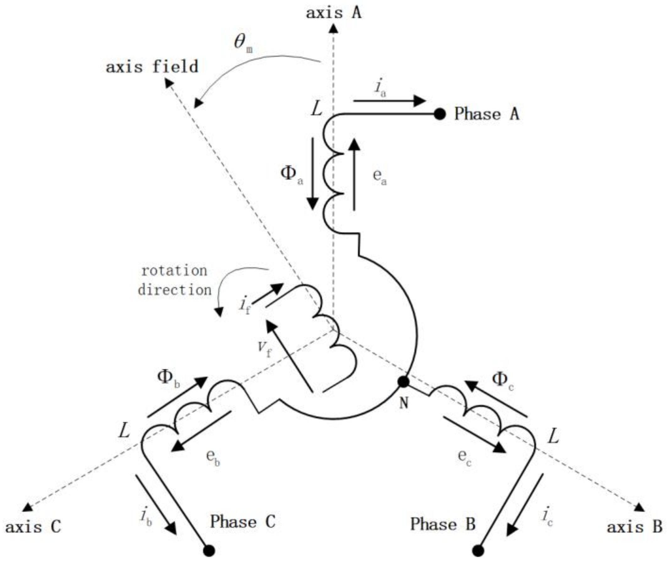
3.1. SM Mathematic Model

The structure and mathematic model of synchronous machines can be found in classic textbooks [16,17]. When the magnetic field is also considered, suitable assumptions are made to simplify analyses. Smooth air gaps form between the stator and rotor, which are concentric cylinders. The magnetic-saturation effect and the magnetic reluctance of the iron core are neglected. The flux leakage and magnetic motive force (MMF) are assumed to be sinusoidal. Also, the electric machine has one pair of poles per phase on the stator, and one pair of poles per phase for the rotor. The self-inductance of the stator and rotor windings is constant. The mutual inductances between the stator windings of different phases are also constant, while the mutual inductances between the rotor and stator windings depend on the angular position of the rotor. The current of the excitation field winding is controlled and constant. The structure of an ideal two-pole SM consists of combining the circuits of a three-phase stator and a rotor that has spatial displacement in its rotation, as shown in Figure 3.
Virtual terminal voltage e , electromagnetic torque T e , and reactive power Q can be deduced as follows [17,18]:
e = M f i f θ
T e = E θ i , i f = c o n s tan t = M f i f i , sin θ
Q = θ M f i f i , c o s θ
where the mechanical rotor angle is replaced by an electric angle, θ = θ m = θ e . M a f , M b f , M c f T are the mutual inductances between the stators and field, which depend on the relative position with a peak value of M f . i = i a , i b , i c T is the stator current, i f is the excitation current, and E is the co-energy stored in the magnetic field for energy conversion?
The output characteristics of synchronous machines require two important equations that address the mechanical part and the electrical part. The mechanical part is determined by a swing equation [19,20], which is:
J d ω d t = T m T e D p ( ω ω g )
where J is the rotating inertia; T m and T e are the mechanical and electromagnetic torque, respectively; D p is the damping factor; and ω and ω g are the angular velocity of the VSG and the grid, respectively.
For the electrical part, the AC side circuit is shown in Figure 4, and the AC side voltage equation is:
L d i a b c d t = e a b c u a b c R i a b c
As for VSG, L and R are the inductance and resistance of the inductance and capacitor (LC) filter, e a b c and u a b c are the voltage of the converter output and the PCC, respectively, and i a b c is the three-phase current.

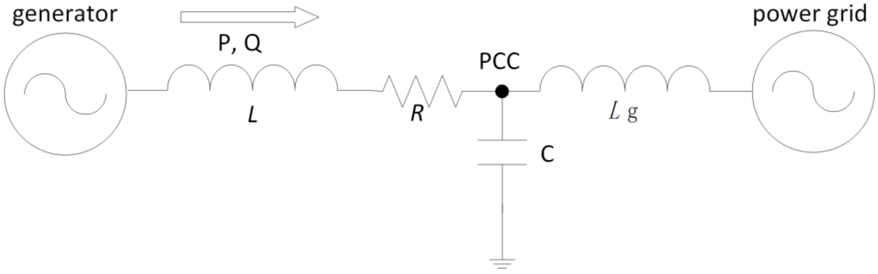
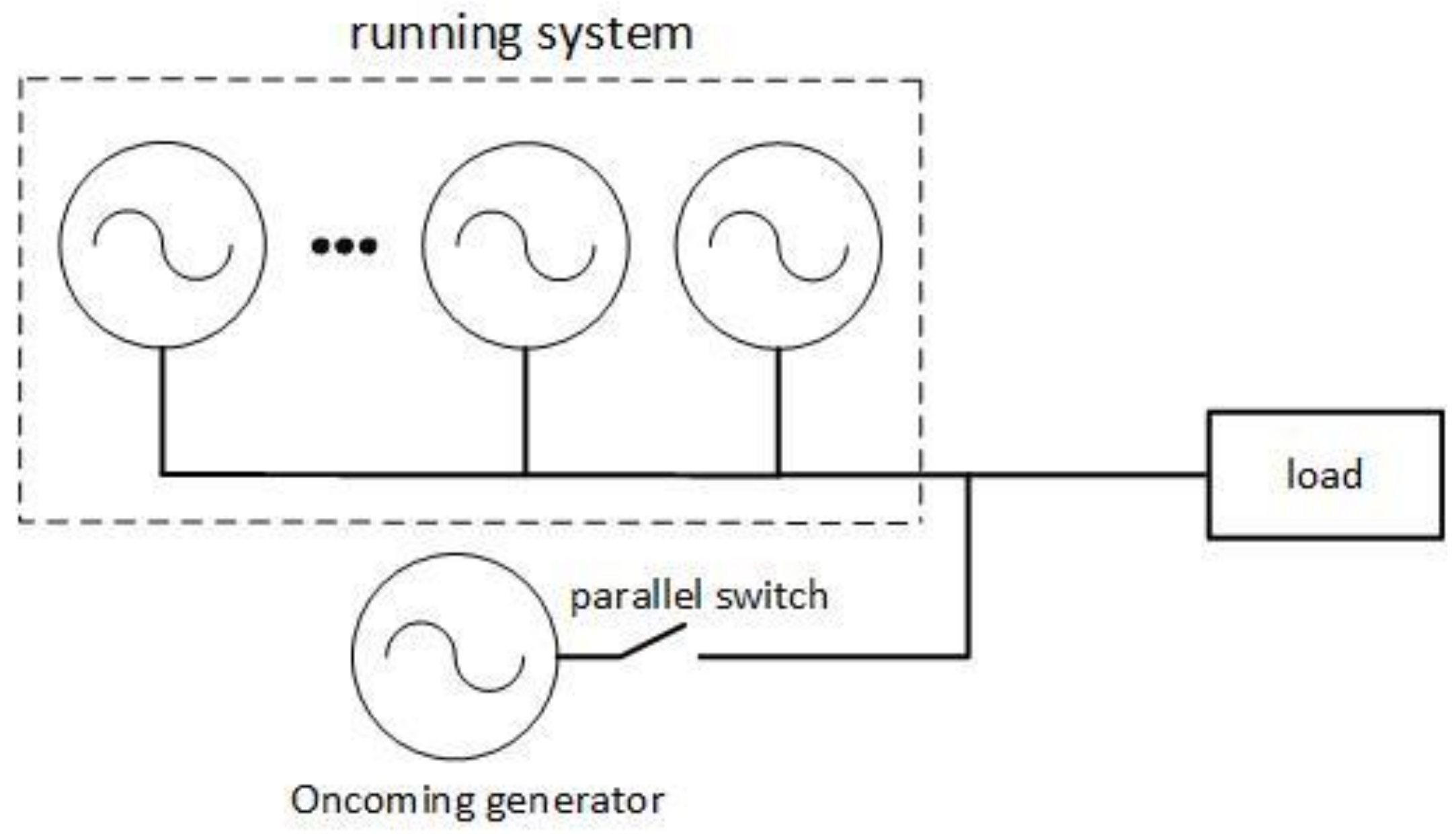
3.2. Synchronization Mechanism

Except for some isolated synchronous generators that supply their own loads, such as generators for emergency or remote regions, conventional power grids are composed of hundreds or thousands of generators that share the entire load of the system. Their parallel operation is realized on the basis of synchronization mechanisms. In conventional power systems, before paralleling, the oncoming SM must compare and adjust its electric voltage output so that they match the amplitude, phase angle, phase sequence, and frequency of the running system. The typical parallel operation of an oncoming generator that is paralleling to the running system is shown in Figure 5. After paralleling, the paralleled machine regulates its output power for energy transmission. Under the unified synchronization mechanism, all of the generators in the entire system operate under the same frequency synchronously, and jointly participate in regulating the frequency and voltage through their inner SM droop characteristics.
Note that the output power (P, Q) of the oncoming synchronous generator is zero before parallel operation, as the parallel switch is off. It can be certified that the SM performs as an enhanced phase lock loop (PLL) called the sinusoid locked loop (SLL) during the parallel operation, which has a frequency channel to synchronize the frequency, and a phase and amplitude channel to synchronize the voltage with the running system [18]. In such a way, synchronous machines have the ability to self-synchronize and plug-and-play.

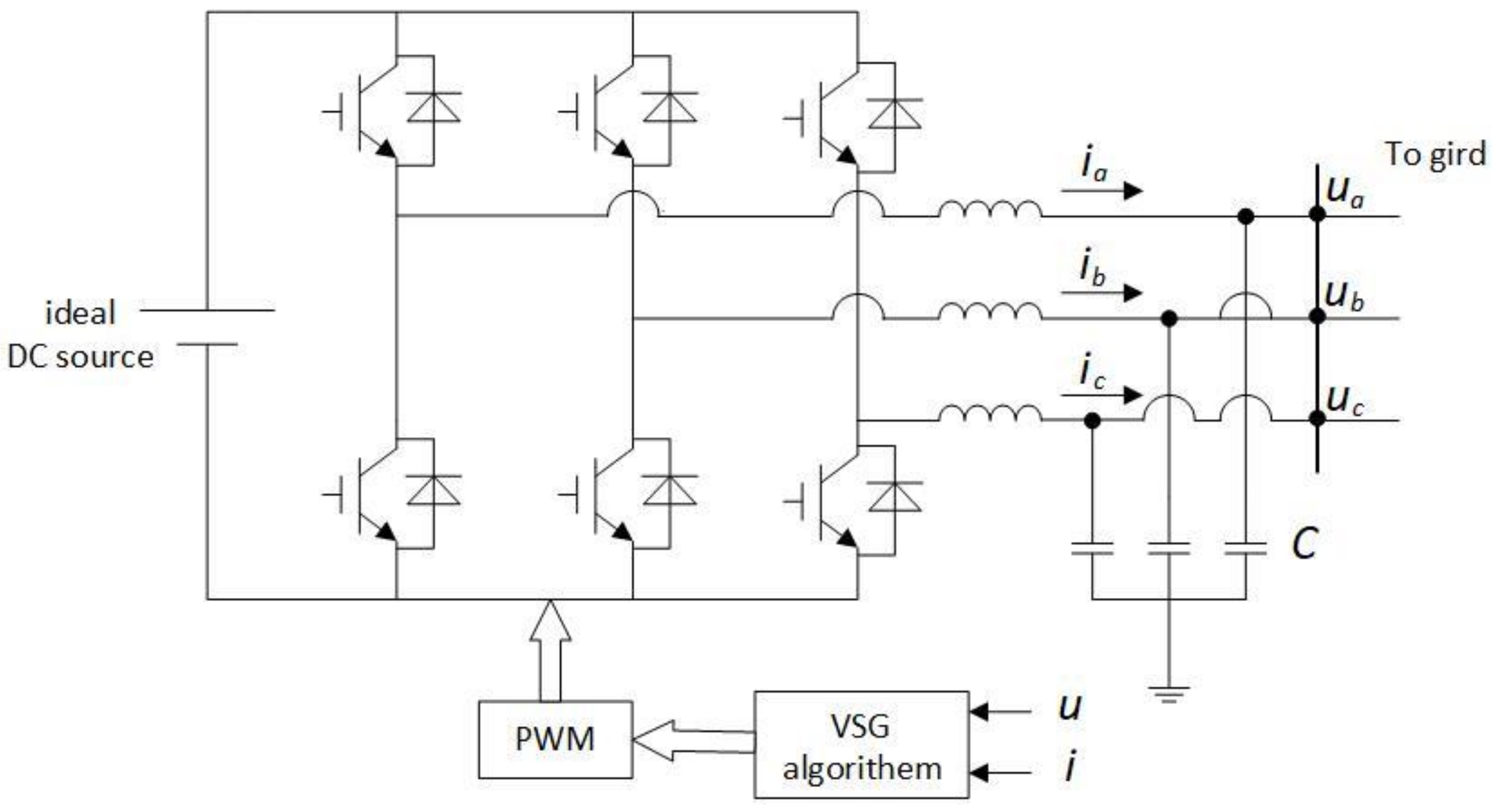
3.3. Implementation of VSG Control

At present, designs for VSG control strategies include implementations that can be categorized into two types that address either the output or topology. Regarding the output type, the VSG implementation can be divided into a controlled current source [11,21,22,23,24,25,26] and a controlled voltage source [12,13,27,28]. The foundation of conventional power systems features synchronous generators as the voltage source. Consequently, they are not able to integrate a large quantity of renewables into the power network as current sources. Regarding the topology type, the VSG implementation can be divided by order, such as a seventh full order [11,21,22], a fifth full order, a reduced fourth order [23,24,25,26], a second order [13,18], and a first order [12,27], as shown in Table 1.
Among the numerous research on VSG implementation, the concept based on second-order model, which includes the swing equation and voltage amplitude given by a reactive power controller, is simple in that can be combined with virtually any control scheme for the converter [28]. A higher-order model may bring unnecessary complexity and difficulty for model implementation. It has also been demonstrated that during normal and abnormal operating conditions, low-order VSM algorithms are more stable than high-order algorithms [29]. The basic schematic of a VSG-control-based power converter is shown is Figure 6, where the DC side can be assumed as an ideal source with infinite capacity.
Magnetic fields are the media for mechanical–electric energy conversion in synchronous machines. Considering electromagnetic transient emulation for specific scenarios (self-synchronization), a “synchroverter” can be modeled by the combination of equations (1) to (4) [18]. Further studies have modified the basic VSG model for better stability by designing parameters for virtual inductors and capacitors [30], small signal analyzation [31], and alternative/self-tuning inertia during dynamic response processes [10].

4. VSG Applications of Power Electronics-Based Units
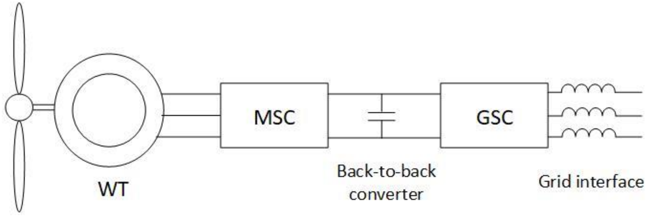
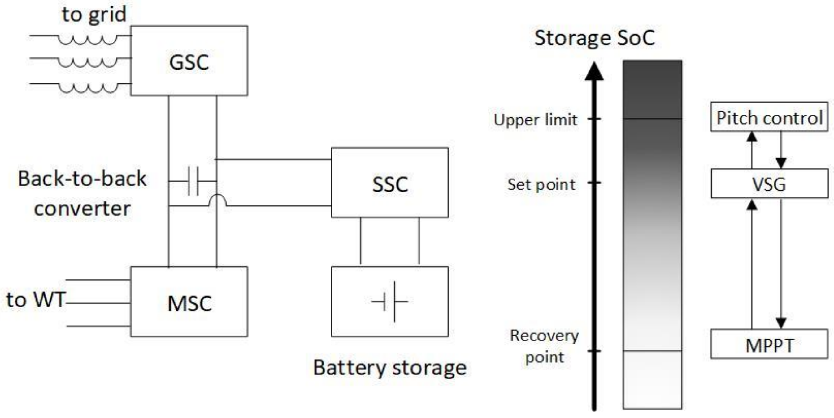
Unlike the theoretical modeling of VSG control, which assumes DC energy to be infinite and constant, practical applications must consider the available generation/storage ability, which is constrained by the status of the system. Once these are addressed, the VSG control strategy can be implemented in applications such as wind turbines, PV panels, energy storage, bidirectional electric vehicle chargers, and flexible loads.

4.1. Wind Turbine

In wind farms, the most common types of wind turbines are the permanent magnet synchronous generator (PMSG) and the doubly-fed induction generator (DFIG). The typical schematic for WT generation that is connected to a grid is shown in Figure 7. The power electronic part of a WT often contains back-to-back converters. The conventional WT control strategy is implemented by vector control (VC) based on a phase-locked loop as a synchronizing technique, which decouples the mechanical part and the electrical part [32,33,34]. The grid-side converter (GSC) extracts the maximum amount of available power and feeds it to the grid without considering the fluctuation of the system frequency or the rotation of the mechanical parts. Thus, despite the actual spinning parts, the WT provides no inertia contribution or power oscillation damping for the grid. The interaction between the wind farm and the grid only consists of several conditions related to fault ride-through. Through modifying the control strategy and system assembly, a VSG-based WT can provide inertia emulation and power oscillation damping to the grid, as well as work in a standalone scenario and respond to dispatch orders from the upper-level operator [35].
The implementation of a VSG on a WT should consider the operational limit and economic factors. Basically, there are two ways to execute inertia emulation and active power damping. One way exploits the hidden kinetic power stored in the rotating parts of the WT such as the blade and rotor. The kinetic power stored in the rotating parts responds to grid frequency fluctuation by releasing/storing active power and providing damping with inertia for the connected grid. Oscillation damping is achieved through fast converter control of the spare generation capacity of the WT. Correspondingly, the operation point transfers from the maximum power point tracking (MPPT) control curve to the virtual synchronous control curve, as the available operation reserve is between the two. In the VSG mode, the available regulation ability should be monitored for smooth recovery, and the operator should be alerted if unidirectional long-time frequency deviation occurs, as it indicates that the wind farm has lost its response ability [36].
The other mode uses the attached energy storage apparatus for active power response [37]. In this mode, a fast storage apparatus is added onto the inner DC bus of back-to-back converters and controlled by a fast bidirectional converter. The machine-side converter (MSC) regulates power balance through rotor speed control, while the grid-side converter (GSC) performs VSG control. The storage-side converter (SSC) is performed to shift work modes according to its state of charge (SOC), which can be divided into an upper power limit, normal VSG operation, and low SOC recovery, as shown in Figure 8. The storage apparatus acts ahead of the VSG–GSC as a fast cache to feed/absorb active power for oscillation damping and mitigate the deviation and rate of change in the DC bus, which reduces the impact that constant frequency disturbance has on the GSC. Furthermore, the WT is available for standalone operation, and it is also dispatchable. However, the capacity of energy storage is theoretically assumed to be large enough, but its economic feasibility and maintenance should be further considered.

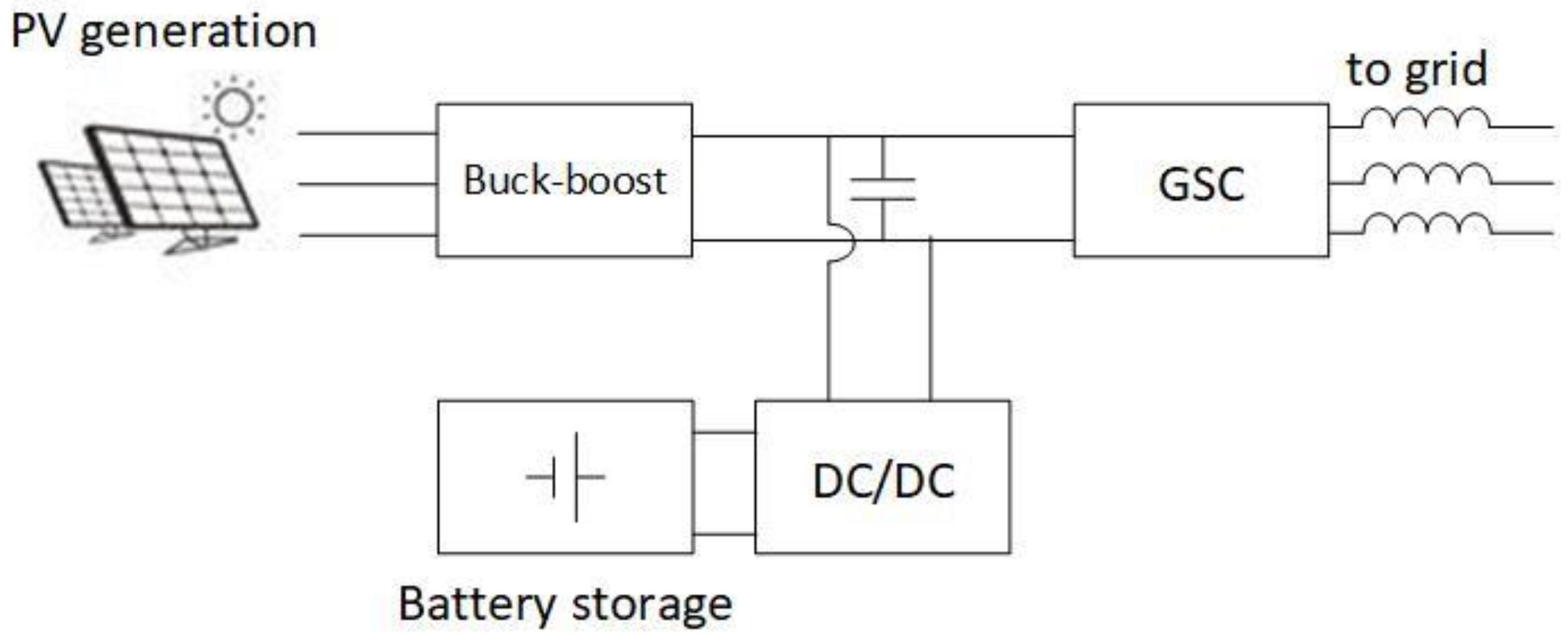
4.2. Solar Generation

Unlike wind turbines, there are no rotating parts in a PV system. As a result, a PV system controlled by MPPT cannot provide spinning reserves or inertia to power systems. In the typical double-stage topology of a solar generation system, the solar power first feeds into a DC/DC converter and then converts it to AC power through a grid-side converter. The VSG control strategy can be implemented in a grid-side converter (GSC) [38,39]. Similar to the design of a grid-connected WT, there are two ways to implement inertia emulation. One is through transitioning the generation curve from MPPT to VSG; the other is by energy storage with a fast, bidirectional DC/DC converter connected to the DC bus, as shown in Figure 9.
The impact of large-scale synchronous PV power plants has been tested in transmission networks at the level of several to hundreds of megawatts MW [40,41,42], which has verified that the impact limits the frequency excursion after a large power imbalance, and mitigates the power oscillation of synchronous machines.

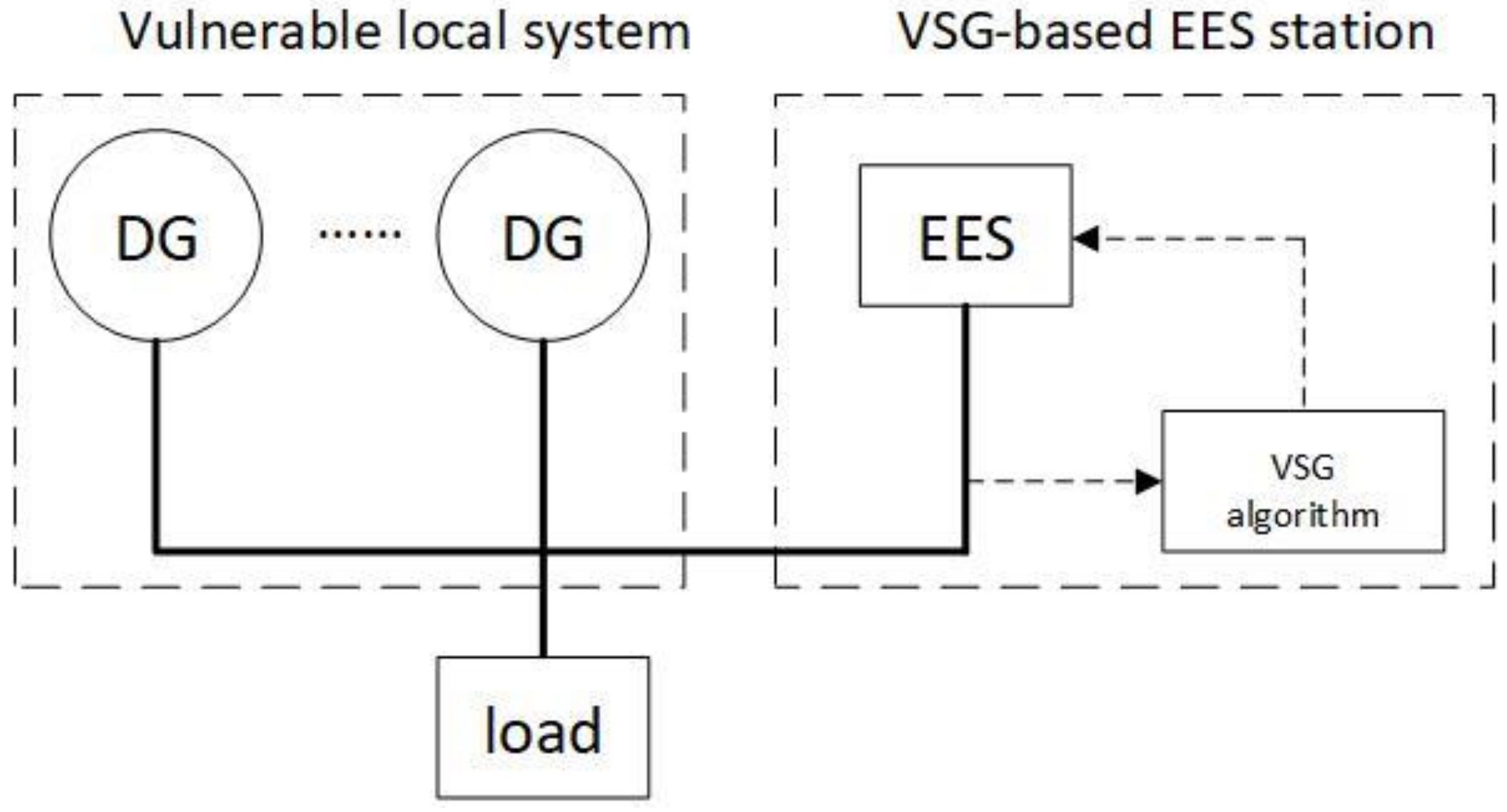
4.3. Auxiliary ESS for Vulnerable Local System

Due to the stochastic generation properties of distributed energy sources (DES), systems fed by high-penetration renewable energy generation have low stability, as they lack sufficient inertia and active power damping to provide frequency support [43,44,45]. An energy storage system (ESS) is an important component because it smooths the renewable energy generation profile and increases its reliability. The ESS system can be implemented at a relatively large scale when coupling renewable energy generation to an existing grid. Besides, remote systems or systems in island scenarios are more vulnerable, as they have a relatively lower generation capacity and a faster and larger demand deviation. If a system fails to operate within the prescribed limits of the existing frequency magnitude or rate of change, tripping occurs, and the load loses power. Power systems with a large amount of renewable energy sources, remote systems, and islanded systems can be briefly categorized into vulnerable local systems due to their low stability. Then, the VSG-controlled ESS can be implemented as an auxiliary apparatus at the interconnection point to provide frequency support and regulate the power balance [43]. The schematic of a typical vulnerable local system with an auxiliary VSG–ESS is shown in Figure 10. The VSG-controlled energy storage system can also be implemented as an uninterruptable power supply or black-start power.

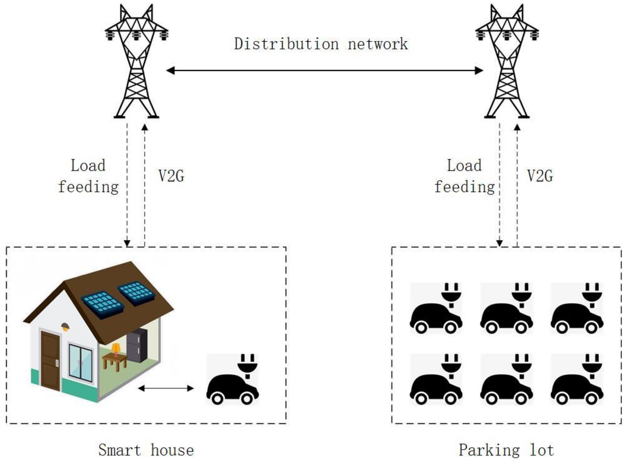
4.4. Bidirectional EV Charger

As the sales of electric vehicles (EV) and plug-in hybrid electric vehicles (PHEV) rise around the world [46], the use of EV can deeply impact current power systems not only as load, but also as potential bulk storage for the distribution network. Vehicle-to-grid (V2G) technology can provide services such as frequency power regulation and load-shifting [47,48,49]. Also, when the bidirectional EV charger is utilized, in addition to energy storage, EV can also be controlled as virtual synchronous motors (VSMs) to provide inertia emulation and virtual spinning reserves, or even feed local systems in standalone mode, as shown in Figure 11. In a low-voltage distribution network, the VSG-based converters are implemented in single-phase [50,51].

4.5. Demand Response

Demand-side management (DSM) was introduced in the late 1970s in response to the oil crisis, which spurned awareness of the need for energy conservation [52]. During consumption fluctuation, load management can improve energy efficiency; this is one of the central advantages of smart grids, and improves the system’s network dynamics, stability, line losses, and operation costs [53,54,55,56]. Most DSM is based on information technology (IT) and authorization from customers to disconnect selected appliances in order to perform a set of functions such as generation/demand forecasting, demand scheduling, and peak shaving, according to the demands of the market. Demand-side response inherently consists of mathematical optimization problems that need to be calculated in real time. These occur through integer programming formulations that find time-variable solutions for every single appliance. Then, the power access for each single appliance is approved or denied by the DSM control. However, since portions of the load can tolerate low power for some time, charging EVs or heating can be extended under continuous low-power consumption. Thus, it is better to perform continuous control for extendable loads in order to improve service quality by reducing rate of demand rejection.
Synchronous machines can adjust their output autonomously according to the status of the system and shift their operation mode from the generators to the motors. Regarding the inner magnetic fields of synchronous machines, the stator magnetic field rotates behind the rotor and tries to align with it while converting the generator mode from mechanical power to electric power. The opposite is the motor mode, which pulls the rotor to rotate [16]. Such conversion can also be implemented by remodifying the control channels of virtual synchronous machines to operate as rectifiers that consume power. In this way, large-scale DC extendable loads can perform as virtual synchronous motors that regulate power in a continuous way, as shown in Figure 12. If a large regional load on a VSG-controlled converter station performs DSM, then considerable operation reserve can be achieved.

5. VSG-Enabled Grid Service for Power Systems

When massive renewable energy sources are integrated into power systems, they introduce a loss of inertia and power fluctuations that lead to large frequency swings, which jeopardize the system’s stability. It is not surprising that rotational inertia has been recognized as a key ancillary service for the stability of power systems. The central question regards the detrimental effects of spatially heterogeneous inertia profiles and how they can be alleviated by inertia emulation throughout the grid [32,57]. Converter-based inertia emulation has been studied for the generation, transmission, and integration of an autonomous microgrid. Further, inertia monitoring [58] and markets [59] have been suggested. Also, it is important to be grid-friendly by providing grid services such as spinning reserves, oscillation damping, and dynamic voltage support.

5.1. Renewable Power Plant

In conventional power system scheduling, conventional power plants, such as coal and nuclear plants, regulate the system’s stability, reliability, and overall energy balance against the multiple uncertainties brought by renewable energy generation. The cost—that more spinning-reserve capacity is scheduled and allocated—is often ignored [60,61]. Through VSG control, renewable power plants can be compatibly integrated with conventional power plants by interacting with the upper grid and following synchronous mechanisms. Thus, power generation can be scheduled and dispatchable from the operation center [62,63,64]. In this way, the excess spinning reserve would be saved, which optimizes the operation cost and efficiency of the entire system.

5.2. Converter Station

A high-voltage direct current (HVDC) is an economic solution for bulk power transmission. It can be classified into two categories: line-commuted converter (LCC)-HVDC and voltage-sourced converter (VSC)-HVDC. The LCC-HVDC has more economic efficiency and system stability for point-to-point long distance transmission, while the VSC-HVDC has more controllability and flexibility by independently decoupling active and reactive power [65,66,67]. The LCC-HVDC and VSC-HVDC can constitute a hybrid multi-terminal HVDC system that is able to utilize the advantages of the HVDC in both categories [68]. When VSC-HVDC stations are controlled by the VSG strategy, they provide virtual inertia and regulate the frequency, which enhances the system’s controllability. Moreover, when feeding a weak AC system (in which the short circuit ratio (SCR) is below three) [69], the PLL in the conventional VSC-HVDC control block degrades the system’s stability and restricts its transmission ability. On the contrary, a VSG-controlled VSC-HVDC can self-synchronize and feed an isolated system [70,71].

5.3. Renewable DG

Future distribution networks will be highly decentralized and comprise massive small-scale renewable DGs that have their own generation paces and various private owners. As a result, it is more difficult to globally regulate the frequency and voltage stability. A VSG control strategy can be adapted to converter integration interfaces to perform not only grid feeding but also services such as dynamic power support and harmonics compensation. Similar to vehicles in the distribution network performing V2G services, a synchronous DG could provide services that include distributed generation to the distribution network.

5.4. Microgrid

A microgrid (MG) can be divided into three categories: the AC-MG, the DC-MG, and the hybrid AC-DC MG [65]. An AC-MG is akin to a small-scale duplication of a distribution system, as it has autonomous operation ability. As the demand for efficiency and performance increases, many AC loads are connected through converters under variable frequency control. Meanwhile, huge quantities of renewable energy sources, energy storage, EV, and electronic instruments that are inherently DC-generating or DC-consuming units are utilized [2]. For the DC-MG, its main advantages are its seamless integration and efficient energy conversion (as DC/AC energy conversion is omitted) [72,73,74]. The central device of the MG system is its bidirectional power converter (BPC), which interconnects interior DGs, energy storage, and local loads with an exterior upper grid. By implementing a VSG control strategy on a BPC, the voltage fluctuation on the AC or DC bus can be restrained. Also, by utilizing internal energy reserves, the MG can provide grid services, too [75]. In some applications, a hybrid AC-DC microgrid is implemented, which combines the advantages of both the AC and DC systems [76]. The two AC sub-MG and DC sub-MG are connected by a bidirectional interlinking converter (BIC). In order to maintain the stability of both sub-MGs in terms of AC frequency and AC/DC bus voltage against generation and consumption fluctuations in both grid-connected and autonomous modes, accurate power exchange, inertia emulation, and dynamic power oscillation damping are the crucial tasks for a BIC [77]. Thus, the VSG control strategy is feasible for interlinking converters between AC and DC microgrids.

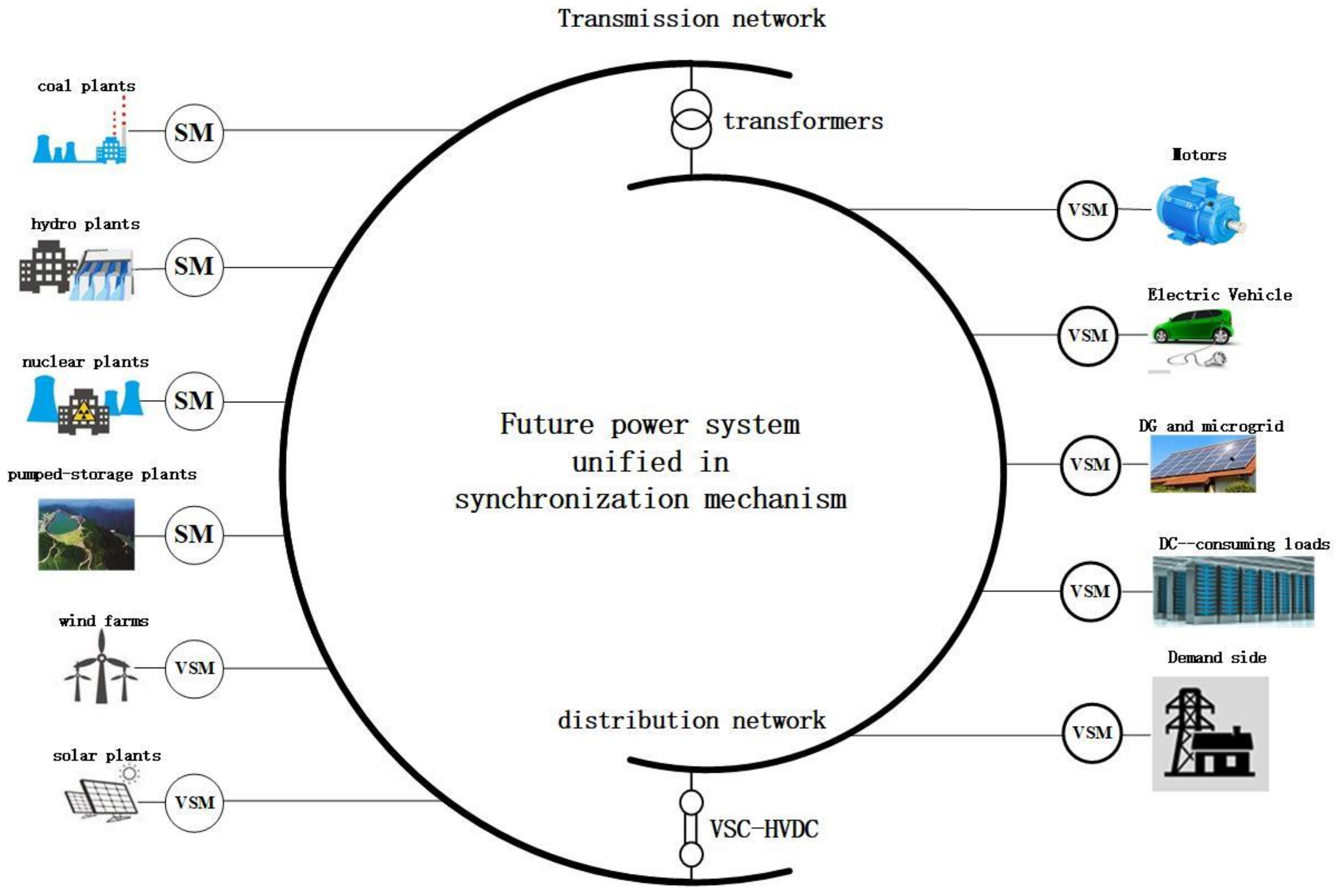
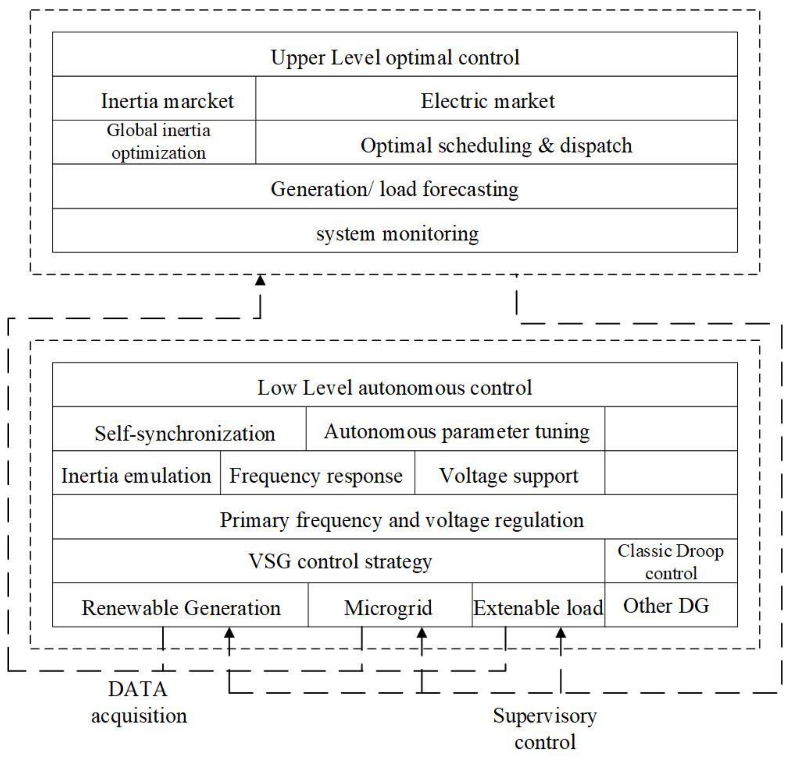
6. Universal Compatibility Architecture for Future Power System

A VSG control strategy can be combined with virtually any converter control scheme, which can be all controlled in a way that closely imitates synchronous machines. Then, autonomous operation is achieved for converter integration. Furthermore, powered by a smart meter and a global IT infrastructure, system-level grid services can also be enabled by monitoring and utilizing local energy resources. As a result, VSG control provides a unified interface for smart grid integration [78,79,80,81]. When most of the power converter-based renewable energy generation units, microgrids, energy storage, electric vehicles, and flexible loads are integrated through a VSG converter, then a universal compatibility architecture can be established to unify all of the aforementioned apparatus with conventional synchronous generators.
The universal compatibility architecture contains universal interface properties, universal regulation mechanisms, and universal internal communication. First, regarding the power grid, every VSG-based unit or SM can be regarded as a synchronous apparatus. They all possess relatively the same output characteristics. The difference is in the internal structure, which consists of a stator, rotor, winding or converter, renewable energy resource (RES), and storage. Second, the fundamental points of a VSM control strategy enables the VSC to possess inertia, damping, and droop characteristics similar to those of a conventional SM, so that all of the VSG-based renewables and conventional generators jointly regulate the stability of the system and overall energy balance under the same synchronization mechanism. All of the VSG-based renewable units act as a controlled voltage source and can be added to pursue optimal scheduling and dispatching according to generation/load forecasting and the market. Third, a universal internal communication channel is formed that includes every synchronous and virtual synchronous unit. When the system frequency fluctuates or power balance is disturbed, every unit acquires exactly the same information—the system running frequency—and provides active power damping with inertia instantaneously and simultaneously. The universal compatibility architecture for future power systems is shown in Figure 13.
The VSG algorithm provides a compatible and grid-friendly way for converter-based smart integration. Under VSG-enabled universal compatibility architecture, the issues of stability, reliability, and scalability brought by high-penetration renewable energy generation are solved. Referring to the hierarchy of traditional system operation, the synchronization mechanism serves as the low-level autonomous control while the district operation center performs the upper-level optimal control. The hierarchy of VSG-enabled system operations is shown in Figure 14.

7. Conclusions

To solve the issues of generation reliability and system stability that the increasing penetration of renewable energy generation has introduced into traditional power systems, a VSG control strategy has been prompted to mimic the outer properties of synchronous machines for converters. In accordance with the classical knowledge of system operations, VSG could also provide high-level grid service. For high-penetration renewable integration, the VSG algorithm provides a compatible and unified standard for smart integration as well as dispatchable and responsible generation for system operations. Based on VSG control, an architecture for future high-penetration renewable energy generation that is universally compatible is established. Referring to the operation knowledge of a traditional grid, there is future research gap regarding the performance enhancement of the dynamic properties as well as the planning, optimal scheduling, and dispatch if the potential capability of a system service provided by renewable energy generation and microgrids is exploited.

Author Contributions

Writing—Review and editing of this paper are finished by W.Z. under the supervision of X.Y.

Funding

This research was funded by National Natural Science Foundation of China-Hebei on the project of “Research on inertia characteristics and control strategy for primary frequency and voltage regulation of DFIG” (No. E201802134).

Acknowledgments

This paper is under the support from State Grid Headquarters Science and Technology Project of “Inertia, damping characteristics and control strategy for primary regulation of DFIG”.

Conflicts of Interest

The authors declare no conflict of interest.

References

  1. Lopes, J.P.; Hatziargyriou, N.; Mutale, J.; Djapic, P.; Jenkins, N. Integrating distributed generation into electric power systems, A review of drivers, challenges and opportunities. Electr. Power Syst. Res. 2007, 77, 1189–1203. [Google Scholar] [CrossRef]
  2. BP Energy Outlook 2018. Available online: https://www.bp.com/en/global/corporate/energyeconomics/energyoutlook.html (accessed on 1 September 2018).
  3. Zhong, Q.C.; Blaabjerg, F.; Cecati, C. Power-Electronics-Enabled Autonomous Power Systems. IEEE Trans. Ind. Electron. 2017, 64, 5904–5906. [Google Scholar]
  4. Rocabert, J.; Luna, A.; Blaabjerg, F.; Rodriguez, P. Control of Power Converters in AC Microgrids. IEEE Trans. Power Electron. 2012, 27, 4734–4749. [Google Scholar] [CrossRef]
  5. Adefarati, T.; Bansal, R.C. Integration of Renewable Distributed Generators into Distribution System: A Review. IET Renew. Power Gen. 2016, 10, 873–884. [Google Scholar] [CrossRef]
  6. Moslehi, K.; Kumar, R. A Reliability Perspective of the Smart Grid. IEEE Trans. Smart Grid 2010, 1, 57–64. [Google Scholar] [CrossRef]
  7. Castronuovo, E.D.; Lopes, J.P. On the Optimization of the Daily Operation of a Wind-hydro power plant. IEEE Trans. Power Syst. 2004, 1599–1606. [Google Scholar] [CrossRef]
  8. Hernandez, L.; Baladron, C.; Aguiar, J.M.; Carro, B.; Sanchez-Esguevillas, A.J.; Lloret, J.; Massana, J. A Survey on Electric Power Demand Forecasting, Future Trends in Smart Grids, Microgrids and Smart Buildings. IEEE Commun. Surv. Tutor. 2014, 16, 1460–1495. [Google Scholar] [CrossRef]
  9. Costanzo, G.T.; Zhu, G.; Anjos, M.F.; Savard, G. A System Architecture for Autonomous Demand Side Load Management in Smart Buildings. IEEE Trans. Smart Grid 2012, 3, 2157–2165. [Google Scholar] [CrossRef]
  10. Bevrani, H.; Ise, T.; Miura, Y. Virtual Synchronous Generators, A survey and New Perspectives. Int. J. Electr. Power Energy Syst. 2014, 54, 244–254. [Google Scholar] [CrossRef]
  11. Hans-Peter, B.; Hesse, R. Virtual Synchronous Machine. In Proceedings of the 9th International Conference Electric Power Quality and Utilization, Barcelona, Spain, 9–11 October 2007. [Google Scholar]
  12. Visscher, K.; De Haan, S.W.H. Virtual Synchronous Machines (VSG’S) for Frequency Stabilization in Future Grids with a Significant Share of Decentralized Generation. In Proceedings of the CIRED Seminar 2008: Smart Grids for Distribution, Frankfurt, Germany, 23–24 June 2008. [Google Scholar]
  13. Zhong, Q.C.; Weiss, G. Synchronverters, Inverters That Mimic Synchronous Generators. IEEE Trans. Ind. Electron. 2011, 58, 1259–1267. [Google Scholar] [CrossRef]
  14. Zhong, Q.C.; Nguyen, P.L.; Ma, Z.; Sheng, W. Self-Synchronized Synchronverters, Inverters Without a Dedicated Synchronous Unit. IEEE Trans. Power Electron. 2014, 29, 617–630. [Google Scholar] [CrossRef]
  15. Zhong, Q.-C. Power-Electronics-Enabled Autonomous Power Systems, Architecture and Technical Routes. IEEE Trans. Ind. Electron. 2017, 64, 5907–5918. [Google Scholar] [CrossRef]
  16. Stephen, J.C. Electric Machinery Fundamentals; McGraw-Hill Education: New York, NY, USA, 2012; pp. 230–267. [Google Scholar]
  17. Stephen, D.U. Fitzgerald & Kingsley’s Electric Machinery; McGraw-Hill Education: New York, NY, USA, 2013; pp. 262–344. [Google Scholar]
  18. Zhong, Q.C.; Hornik, T. Control of Power Inverters in Renewable Energy and Smart Grid Integration; John Wiley & Sons: Hoboken, NJ, USA, 2012; pp. 277–296. [Google Scholar]
  19. Machowski, J.; Bialek, J.W.; Bumby, J.R. Power System Dynamics and Stability; Wiley: Chichester, UK, 1997; Chapter 5. [Google Scholar]
  20. Kimbark, E.W. Power System Stability, Volume III Synchronous Machines; John Wiley & Sons, Inc.: New York, NY, USA, 1956; Chapter XIV. [Google Scholar]
  21. Hesse, R.; Turschner, D.; Beck, H.-P. Micro grid stabilization using the Virtual Synchronous Machine (VISMA). In Proceedings of the International Conference on Renewable Energies and Power Quality, ICREPQ’09, Valencia, Spain, 15-17 April 2009; p. 6. [Google Scholar]
  22. Pelczar, C.; Stubbe, M.; Beck, H.-P.; Zirn, O. FPGA Current Controller for the Virtual Synchronous Machine. In Proceedings of the International Exhibition and Conference for Power Electronics, Intelligent Motion, Renewable Energy and Energy Management PCIM Europe, Nuremberg, Germany, 8–10 May 2012; pp. 138–145. [Google Scholar]
  23. Chen, Y.; Hasse, R.; Turschner, D.; Beck, H.-P. Comparison of methods for implementing virtual synchronous machine on inverters. In Proceedings of the International Conference on Renewable Energies and Power Quality, ICREPQ’12, Santiago de Compostela, Spain, 28–30 March 2012; pp. 1–6. [Google Scholar]
  24. Chen, Y.; Hesse, R.; Turschner, D.; Beck, H.-P. Dynamic Properties of the Virtual Synchronous Machine (VSIMA). In Proceedings of the International Conference on Renewable Energies and Power Quality, ICREPQ’11, Las Palmas, Spain, 13–15 April 2011; pp. 1–5. [Google Scholar]
  25. Chen, Y.; Hesse, R.; Turschner, D.; Beck, H.-P. Improving the Grid Power Quality Using Virtual Synchronous Machines. In Proceedings of the 2011 International Conference on Power Engineering, Energy and Electrical Drives, PowerEng 2011, Torremolinos, Malaga, Spain, 11–13 May 2011; pp. 1–6. [Google Scholar]
  26. Chen, Y.; Hesse, R.; Turschner, D.; Beck, H.-P. Investigation of the Virtual Synchronous Machine in the Island Mode. In Proceedings of the 2012 3rd IEEE Innovative Smart Grid Technologies Europe Conference, Berlin, Germany, 15–17 October 2012; pp. 1–6. [Google Scholar]
  27. Driesen, J.; Visscher, K. Virtual Synchronous Generators. In Proceedings of the IEEE Power and Energy Society 2008 General Meeting, Conversion and Delivery of Energy in the 21st, Pittsburgh, PA, USA, 20–24 July 2008; pp. 1–3. [Google Scholar]
  28. D’Arco, S.; Suul, J.A. Virtual Synchronous Machines—Classification of Implementations and Analysis of Equivalence to Droop Controllers for Microgrids. In Proceedings of the IEEE Powertech Grenoble Conference, Grenoble, France, 16–20 June 2013. [Google Scholar]
  29. Alrajhi Alsiraji, H.; El-Shatshat, R. Comprehensive assessment of virtual synchronous machine based voltage source converter controllers. IET Gen. Transm. Distrib. 2017, 11, 1762–1769. [Google Scholar] [CrossRef]
  30. Natarajan, V.; Weiss, G. Synchronverters with Better Stability Due to Virtual Inductors, Virtual Capacitors, and Anti-Windup. IEEE Trans. Ind. Electron. 2017, 64, 5994–6004. [Google Scholar] [CrossRef]
  31. Wu, H.; Ruan, X.; Yang, D.; Chen, X.; Zhao, W.; Lv, Z.; Zhong, Q.C. Small-Signal Modeling and Parameters Design for Virtual Synchronous Generators. IEEE Trans. Ind. Electron. 2016, 63, 4292–4303. [Google Scholar] [CrossRef]
  32. Singh, B.; Mahanty, R.; Singh, S.P. Social welfare maximization for congestion management in multiutility market using improved PSO incorporating transmission loss cost allocation. Int. Trans. Electr. Energy Syst. 2018, 28. [Google Scholar] [CrossRef]
  33. Alipoor, J.; Miura, Y.; Ise, T. Stability Assessment and Optimization Methods for Microgrid With Multiple VSG Units. IEEE Trans. Smart Grid 2018, 9, 1462–1471. [Google Scholar] [CrossRef]
  34. Wang, Y.; Meng, J.; Zhang, X.; Xu, L. Control of PMSG-Based Wind Turbines for System Inertial Response and Power Oscillation Damping. IEEE Trans. Sustain. Energy 2015, 6, 565–574. [Google Scholar] [CrossRef] [Green Version]
  35. Wang, S.; Hu, J.; Yuan, X. Virtual Synchronous Control for Grid-Connected DFIG-Based Wind Turbines. IEEE J. Emerg. Sel. Top. Power Electron. 2015, 3, 932–944. [Google Scholar] [CrossRef]
  36. Wang, S.; Hu, J.; Yuan, X.; Sun, L. On Inertial Dynamics of Virtual-Synchronous-Controlled DFIG-Based Wind Turbines. IEEE Trans. Energy Convers. 2015, 30, 1691–1702. [Google Scholar] [CrossRef]
  37. Ma, Y.; Cao, W.; Yang, L.; Wang, F.F.; Tolbert, L.M. Virtual Synchronous Generator Control of Full Converter Wind Turbines with Short-Term Energy Storage. IEEE Trans. Ind. Electron. 2017, 64, 8821–8831. [Google Scholar] [CrossRef]
  38. Alatrash, H.; Mensah, A.; Mark, E.; Haddad, G.; Enslin, J. Generator Emulation Controls for Photovoltaic Inverters. In Proceedings of the 8th International Conference on Power Electronics—ECCE Asia, Jeju, Korea, 30 May–3 June 2011; pp. 996–1011. [Google Scholar]
  39. Alatrash, H.; Mensah, A.; Mark, E.; Haddad, G.; Enslin, J. Generator Emulation Controls for Photovoltaic Inverters. IEEE Trans. Smart Grid 2012, 3, 996–1011. [Google Scholar] [CrossRef]
  40. Yan, R.; Saha, T.K.; Meredith, P.; Ananth, A.; Hossain, M.I. Megawatt-scale solar variability study, an experience from a 1.2 MWp photovoltaic system in Australia over three years. IET Renew. Power Gener. 2016, 10, 1229–1236. [Google Scholar] [CrossRef]
  41. Watson, J.D.; Watson, N.R.; Santos-Martin, D.; Wood, A.R.; Lemon, S.; Miller, A.J. Impact of solar photovoltaics on the low-voltage distribution network in New Zealand. IET Gener. Transm. Distrib. 2016, 10, 1–9. [Google Scholar] [CrossRef]
  42. Remon, D.; Cañizares, C.A.; Rodriguez, P. Impact of 100-MW-scale PV plants with synchronous power controllers on power system stability in northern Chile. IET Gener. Transm. Distrib. 2017, 11, 2958–2964. [Google Scholar] [CrossRef] [Green Version]
  43. Fang, L.; Niu, Y.; Zu, Q.; Wang, S. Energy management strategy based on energy storage equalization technology and transferable load. Int. Trans. Electr. Energy Syst. 2018, 28, e2599. [Google Scholar] [CrossRef]
  44. Sivakumar, P.; Arutchelvi, M.S. Modified composite power control strategy for grid connected wind-PV systems with unbalanced nonlinear current. Int. Trans. Electr. Energy Syst. 2018, 28, e2587. [Google Scholar] [CrossRef]
  45. Miguel, A.; Torres, L.; Luiz, A.C.; Lopes Luis, A.; Morán, T.; José, R.; Espinoza, C. Self-Tuning Virtual Synchronous Machine, A Control Strategy for Energy Storage Systems to Support Dynamic Frequency Control. IEEE Trans. Energy Convers. 2014, 29, 833–840. [Google Scholar]
  46. The Information Council for Road Traffic in Norway, National Sales Statistics for 2015. Available online: http//www.ofvas.no/bilsalget-i2015/category679.html (accessed on 1 September 2016).
  47. Lopes, J.A.P.; Soares, F.J.; Almeida, P.M.R. Integration of electric vehicles in the electric power systems. Proc. IEEE 2011, 99, 168–183. [Google Scholar] [CrossRef]
  48. Yilmaz, M.; Krein, P.T. Review of the impact of vehicle-to-grid technologies on distribution systems and utility interfaces. IEEE Trans. Power Electron. 2013, 28, 5673–5689. [Google Scholar] [CrossRef]
  49. Tan, K.M.; Ramachandaramurthy, V.K.; Yong, J.Y. Integration of electric vehicles in smart grid, A review on vehicle to grid technologies and optimization techniques. Sustain. Energy 2016, 53, 720–732. [Google Scholar] [CrossRef]
  50. Berigai, A.; Rakesh, R.; Sabha, M.; Arya, R. Bidirectional converter for electric vehicle battery charging with power quality features. Int. Trans. Electr. Energy Syst. 2018, 28, e2589. [Google Scholar] [CrossRef]
  51. Suul, J.A.; D’Arco, S.; Guidi, G. Virtual Synchronous Machine-Based Control of a Single-Phase Bi-Directional Battery Charger for Providing Vehicle-to-Grid Services. IEEE Trans. Ind. Appl. 2016, 52, 3234–3244. [Google Scholar] [CrossRef]
  52. Gellings, C.W. The concept of demand-side management for electric utilities. Proc. IEEE 1985, 73, 1468–1470. [Google Scholar] [CrossRef]
  53. Molderink, A.; Bakker, V.; Bosman, M.G.C.; Hurink, J.L.; Smit, G.J.M. Domestic energy management methodology for optimizing efficiency in smart grids. In Proceedings of the IEEE Bucharest PowerTech, Bucharest, Romania, 28 June–2 July 2009; pp. 1–7. [Google Scholar]
  54. Dai, Y.; Gao, Y.; Gao, H.; Zhu, H. A demand response approach considering retailer incentive mechanism based on Stackelberg game in smart grid with multi retailers. Int. Trans. Electr. Energy Syst. 2018, 28, e2590. [Google Scholar] [CrossRef]
  55. Vahedipour-Dahraie, M.; Najafi, H.R.; Anvari-Moghaddam, A.; Guerrero, J.M. Security-constrained unit commitment in AC microgrids considering stochastic price-based demand response and renewable generation. Int. Trans. Electr. Energy Syst. 2018, 28, e2596. [Google Scholar] [CrossRef]
  56. Shi, J.; Oren, S.S. Stochastic unit commitment with topology control recourse for power system with large-scale renewable integration. IEEE Trans. Power Syst. 2018, 33, 3315–3324. [Google Scholar] [CrossRef]
  57. Ulbig, A.; Borsche, T.S.; Andersson, G. Impact of low rotational inertia on power system stability and operation. Proc. IFAC World Congr. 2014, 47, 7290–7297. [Google Scholar] [CrossRef]
  58. Ashton, P.; Saunders, C.; Taylor, G.; Carter, A.; Bradley, M. Inertia estimation of the GB power system using synchrophasor measurements. IEEE Trans. Power Syst. 2015, 30, 701–709. [Google Scholar] [CrossRef]
  59. Ela, E.; Gevorgian, V.; Tuohy, A.; Kirby, B.; Milligan, M.; O’Malley, M. Market designs for the primary frequency response ancillary service— Part I, Motivation and design. IEEE Trans. Power Syst. 2014, 29, 421–431. [Google Scholar] [CrossRef]
  60. Poolla, B.K.; Bolognani, S.; Dörfler, F. Optimal Placement of Virtual Inertia in Power Grids. IEEE Trans. Autom. Control 2017, 62, 6209–6220. [Google Scholar] [CrossRef] [Green Version]
  61. Ummels, B.C.; Kling, W.L.; Pelgrum, E. Integration of large-scale wind power and use of energy storage in the Netherlands’ electricity supply. IET Renewable Power Gen. 2008, 2, 34–36. [Google Scholar] [CrossRef]
  62. O’Dwyer, C.; Ryan, L.; Flynn, D. Efficient Large-Scale Energy Storage Dispatch, Challenges in Future High Renewable Systems. IEEE Trans. Power Syst. 2017, 32, 3439–3450. [Google Scholar] [CrossRef]
  63. Yang, Y.; Ye, Q.; Tung, L.J.; Greenleaf, M.; Li, H. Integrated Size and Energy Management Design of Battery Storage to Enhance Grid Integration of Large-Scale PV Power Plants. IEEE Trans. Ind. Electron. 2018, 65, 394–402. [Google Scholar] [CrossRef]
  64. Wang, K.; Qi, C.; Huang, X.; Li, G. Large disturbance stability evaluation of interconnected multi-inverter power grids with VSG model. J. Eng. 2017, 2017, 2483–2488. [Google Scholar] [CrossRef]
  65. Li, G.; Li, G.; Li, H.; Zhao, C.; Yin, M. Research on hybrid HVDC. Proc. Int. Conf. Power Syst. Technol. 2004, 2, 1607–1612. [Google Scholar]
  66. Torres-Olguin, R.E.; Molinas, M.; Undeland, T.M. A controller in DQ synchronous reference frame for hybrid HVDC transmission system. Proc. Int. Power Electron. Conf. 2010, 376–383. [Google Scholar]
  67. Kotb, O.; Sood, V.K. A hybrid HVDC transmission system supplying a passive load. In Proceedings of the 2010 IEEE Electrical Power & Energy Conference, Halifax, NS, Canada, 25–27 August 2010; pp. 1–5. [Google Scholar]
  68. Dong, S.; Chi, Y.; Li, Y. Active Voltage Feedback Control for Hybrid Multiterminal HVDC System Adopting Improved Synchronverters. IEEE Trans. Power Deliv. 2016, 31, 445–455. [Google Scholar] [CrossRef]
  69. Saric, M.; Hivziefendic, J.; Konjic, T.; Ktena, A. Distributed generation allocation considering uncertainties. Int. Trans. Electr. Energy Syst. 2018, 28, e2585. [Google Scholar] [CrossRef]
  70. Guide for Planning DC Links Terminating at AC Systems Locations Having Low Short-Circuit Capacities, Part I, AC/DC Interaction Phenomena; IEEE Standard: New York, NY, USA, 1997.
  71. Lu, S.; Xu, Z.; Xiao, L.; Jiang, W.; Bie, X. Evaluation and Enhancement of Control Strategies for VSC Stations Under Weak Grid Strengths. IEEE Trans. Power Syst. 2018, 33, 1836–1847. [Google Scholar] [CrossRef]
  72. Hamzeh, M.; Ghazanfari, A.; Mohamed, Y.A.; Karimi, Y. Modeling and design of an oscillatory current-sharing control strategy in DC microgrids. IEEE Trans. Ind. Electron. 2015, 62, 6647–6657. [Google Scholar] [CrossRef]
  73. Huang, P.; Liu, P.; Xiao, W.; el Moursi, M.S. A novel droop-based average voltage sharing control strategy for DC microgrids. IEEE Trans. Smart Grid 2015, 6, 1096–1106. [Google Scholar] [CrossRef]
  74. Lu, X.; Sun, K.; Guerrero, J.M.; Vasquez, J.C.; Huang, L. State-of charge balance using adaptive droop control for distributed energy storage systems in DC microgrid applications. IEEE Trans. Ind. Electron. 2014, 61, 2804–2815. [Google Scholar] [CrossRef]
  75. Wu, W.; Chen, Y.; Luo, A.; Zhou, L.; Zhou, X.; Yang, L.; Dong, Y.; Guerrero, J.M. A Virtual Inertia Control Strategy for DC Microgrids Analogized with Virtual Synchronous Machines. IEEE Trans. Ind. Electron. 2017, 64, 6005–6016. [Google Scholar] [CrossRef]
  76. Majumder, R. A hybrid microgrid with dc connection at back to back con converters. IEEE Trans. Smart Grid 2014, 5, 251–259. [Google Scholar] [CrossRef]
  77. Alsiraji, H.A.; Radwan, A.A.; El-Shatshat, R. Modelling and analysis of a synchronous machine-emulated active intertying converter in hybrid AC/DC microgrids. IET Gener. Transm. Distrib. 2018, 12, 2539–2548. [Google Scholar] [CrossRef]
  78. Zhong, Q.-C. Virtual Synchronous Machines—A unified interface for smart grid integration. IEEE Power Electron. Mag. 2016, 3, 18–27. [Google Scholar] [CrossRef]
  79. Li, H.; Eseye, A.T.; Zhang, J.; Zheng, D. Optimal energy management for industrial microgrids with high-penetration renewables. Prot. Control Mod. Power Syst. 2017, 2, 122–135. [Google Scholar] [CrossRef]
  80. Gaber, M.; Shabib, G.; Elbaset, A.A.; Mitani, Y. Optimized coordinated control of LFC and SMES to enhance requency stability of a real multi-source power system considering high renewable energy penetration. Prot. Control Mod. Power Syst. 2018, 3, 407–421. [Google Scholar]
  81. Gaber, M.; Mohamed, E.A.; Shabib, G.; Elbaset, A.A.; Mitani, Y. Microgrid dynamic security considering high penetration of renewable energy. Prot. Control Mod. Power Syst. 2018, 3, 236–246. [Google Scholar]
Figure 1. Traditional power system operation on a time-scale.
Applsci 09 01484 g001
Figure 2. Technical gap of virtual synchronous generator (VSG)-based renewable integration.
Applsci 09 01484 g002
Figure 3. Structure of a two-pole electric machine.
Applsci 09 01484 g003
Figure 4. Alternating current (AC) side circuit of synchronous generator.
Applsci 09 01484 g004
Figure 5. Parallel operation for an oncoming generator that needs to compare and adjust its parameters in order to match those of the running system.
Applsci 09 01484 g005
Figure 6. Schematic of VSG modeling.
Applsci 09 01484 g006
Figure 7. Schematic of grid-connected wind turbine (WT) system.
Applsci 09 01484 g007
Figure 8. Fast storage as an additional apparatus for system damping.
Applsci 09 01484 g008
Figure 9. Schematic diagram of double-stage photovoltaic (PV) generation with energy storage on a direct current (DC) bus.
Applsci 09 01484 g009
Figure 10. Schematic of a vulnerable AC system with an auxiliary VSG energy storage system (ESS).
Applsci 09 01484 g010
Figure 11. Framework for vehicle-to-grid (V2G) service.
Applsci 09 01484 g011
Figure 12. Framework of system operation and load management.
Applsci 09 01484 g012
Figure 13. Universal compatibility architecture of future power systems.
Applsci 09 01484 g013
Figure 14. Diagram of VSG-enabled system operation.
Applsci 09 01484 g014
Table 1. Classification of VSG modeling. SG: synchronous generators.
ModelModel ImplementationGeneral Comments
Seventh orderElectric, magnetic, swing equation of stator and rotor windingFull representation of SG dynamics.
Fifth or fourth orderElectric, magnetic, swing equation of stator windingOnly stator winding is considered compared to seventh-order model.
Second orderSwing equation and voltage amplitude given by the reactive power controllerSimple scheme for converter implementation for a close imitation.
First orderInertial emulation by power response calculated from grid voltage trackingIncapable of isolated operation.

