Abstract
A simple and effective approach to semiconductor laser linewidth narrowing via mutual injection locking is proposed and demonstrated in both short and long delay regimes. A theoretical analysis is presented to investigate the linewidth behavior of semiconductor lasers under mutual injection locking. Experimental demonstrations in short and long delay regimes are implemented by integrated devices and a fiber link system, respectively. Locking condition and dependence of laser linewidth on coupling parameters in both regimes are studied, confirming mutual injection locking as a practical method for linewidth narrowing. For the short-delayed integrated lasers, a linewidth narrowing factor of 13 is demonstrated and sub-MHz linewidth is achieved, while for the long-delayed lasers coupled by fiber link, the intrinsic linewidth is reduced to sub-100 Hz.
1. Introduction
Semiconductor lasers feature small foot-prints, low power consumption, high flexibility and compatibility with photonic integration circuits, hence they are widely used in various optical systems. Lasers suffer from frequency noise, which results from spontaneous emission and carrier noise, and the spectrum purity always casts a performance limit on different applications. In coherent optical communications with high-order modulation format, laser phase noise disperses the constellation and causes bit error [1,2,3]. In atomic sensing, laser frequency noise converts to amplitude noise after interaction with atom gas, limiting the stability or sensitivity of atomic sensors [4,5]. In addition, the spectrum width also determines the resolution of spectroscopy detection [6], sensitivity of fiber sensing [7] and the dynamic range of lidar [8], to name just a few. Therefore, it is quite worthwhile to devote efforts to narrowing laser linewidth for further improvement of system performance.
The linewidth of semiconductor lasers is typically in the range of a few MHz. Optical injection provides a new degree of freedom for improving the performance of semiconductor lasers. In the case of unidirectional injection locking, the linewidth of the slave laser follows that of the master [9], so that a narrow linewidth master laser is required to improve the spectral purity of the slave laser [10]. As for self-injection or external cavity, a fraction of light emitted from the gain material is fed back through a low loss external cavity, hence the laser linewidth is reduced by increased photon lifetime. Recent research centers on the realization techniques of self-injection, such as low loss Si [11,12] or Si3N4 [13,14] ring resonator, fiber components based feedback circuit [15,16], assembled confocal Fabry–Perot (FP) cavity [17] and CaF2 cavity [18]. These structures rely on high Q cavity or multiple mode selection components.
In this work, we propose and demonstrate a simple but effective approach to linewidth narrowing based on mutual injection locking (MIL) of semiconductor lasers. Previous research on mutual coupling mainly focuses on the nonlinear dynamics [19,20], which can be exploited to realize random sequences generation [20], chaos synchronization [21,22], modulation characteristics enhancement [23] and photonic microwave generation [24]. In addition, it is also used for coherent combining [25,26] and lasing threshold reduction [27]. However, to the best of our knowledge, there have been relatively few reports on laser linewidth or frequency noise characteristics upon mutual injection locking.
A systemic study on the linewidth narrowing mechanism, locking condition and frequency noise reduction is carried out in the investigation. Modified mutual coupling rate equations incorporating Langevin noise sources are presented to analyze the mechanisms for frequency noise reduction of mutually injection locked lasers. Previous experiments indicate that laser behaves differently for short delay (τd < 1/fRO) and long delay (τd > 1/fRO) [19,20,28], where τd is the coupling delay time and fRO represents the relaxation oscillation frequency. Therefore, experiments are carried out in both regimes: monolithically integrated mutually coupled Distributed Feedback(DFB) lasers are employed to investigate frequency noise performance in short delay regimes, while a fiber link based system is adopted for the study of long delay regimes. Locking condition and the dependence of laser frequency noise on system parameters are investigated in both regimes, confirming mutual injection locking as a practical method for linewidth narrowing.
This paper is organized as follows. In Section 2, a theoretical model is presented to clarify the frequency noise suppression in mutually injection locked lasers. In Section 3, locking conditions and linewidth narrowing in mutually injection locked lasers with short delay are studied through integrated devices. The behavior of mutually coupled lasers with long delay are investigated in Section 4, with an emphasis on the differences between the two regimes. The special features of the proposed approach are then discussed in comparison with classical techniques such as external cavity lasers.
2. Theoretical Analysis
Figure 1 depicts a generalized mutual injection locking configuration between two semiconductor lasers. The optical path can be realized on chip, in free-space or through fiber link. The light emitted from one laser is injected into the other with a coupling strength κc and a coupling phase φp as well as a delay τd. Hence, the optical field of each laser is distorted not only by its internal noise sources, but by the noise of the other lasers via optical coupling as well. To investigate the linewidth characteristics of mutually coupled lasers, coupled single mode rate equations are adopted to analyze their frequency noise.

Figure 1.
Generalized configuration of mutually coupled semiconductor lasers.
Different from commonly used Lang–Kobayashi equations [29,30,31], laser field E(t) is replaced by E(t) = S1/2exp(iφ) to facilitate the introduction of Langevin noise. The modified equations are given in Equation (1), where S, N and φ represent photon number, carrier number and optical phase, respectively. Both lasers are assumed to share the same parameters listed in Table 1, together with the definition of each symbol. Fn, Fs and Fp are Langevin forces driving the equations of carrier, photon and phase. Due to carrier-photon interaction in a semiconductor laser, Fn and Fs are correlated and cannot be described by white Gaussian noise directly. A noise generation technique as described in [32] is employed and the laser-parameter related noise sources are given by Equation (2).

Table 1.
Laser parameters.
Here x1(t), x2(t) and x3(t) are independent random sequences taken from standard normalized distribution and Δt is the simulation step.
Laser frequency noise and spectrum characteristics under mutual injection locking is investigated numerically, and three mechanisms are found for linewidth narrowing.
The first one is photon number increase due to optical injection. Figure 2a shows the variation of photon number, carrier number and lasing frequency of both lasers when the detuning is swept from −15 to 15 GHz. In the range of −8~7 GHz, carrier and photon number in both lasers are stable and their lasing frequency are the same, indicating stable mutual injection locking. In our simulations, the two coupled lasers are assumed to be identical.
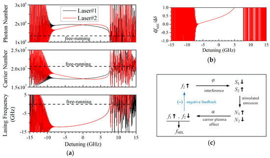
Figure 2.
(a) Variation of the photon number, carrier number and lasing frequency of mutually coupled lasers as the detuning varies from −15 to 15 GHz. (τd = 5 ps, κc = 2 × 10¹⁰/s, φp = 0); (b) relation between injection locked lasing frequency fMIL and detuning δ; (c) negative feedback diagram.
The strong bidirectional optical injection leads to an increase in photon number within the laser cavity by 1.7 dB at zero detuning. As a result, the carrier density is reduced by 17.2% via enhanced stimulated emission. The refractive index of active region decreases due to the carrier plasma effect and lasing frequency is redshifted by 10.9 GHz. Laser frequency noise results from spontaneous emission and carrier fluctuation. For free-running lasers, the carrier number is clamped at the threshold level and the laser linewidth is in reverse proportion to the photon number. Optical injection increases coherent photon number in the laser cavity at a given current, thus improving coherence of the laser. Nevertheless, the increase of optical power is rather limited, and is estimated to result in a linewidth narrowing factor of only 1.48 according to our simulation.
The second mechanism is mutual phase-locking between the coupled lasers. The behavior of mutually coupled lasers is determined by (κc,φp,δ), and the simulation results in Figure 2a depict the laser state under different detuning δ. Mutual injection locking occurs when δ is around zero, with both lasers lasing at the same frequency fMIL. It is important to notice that the variation of fMIL is small when δ fluctuates. According to the third differential equation in Equation (1), the frequency noise of the lasers is mathematically equivalent to the fluctuation of δ. Hence the frequency noise of the mutually injection locked lasers is reduced as compared with the free-running case. Figure 2b shows that dfMIL/dδ <1 around zero detuning, indicating a suppression of frequency fluctuation.
A negative feedback mechanism for frequency noise reduction exists in the mutually injection locked system, as depicted in Figure 2c. This results from the interplay between the photon and carrier, and their influence on the phase and frequency of the mutually coupled lasers. Supposing that the frequency of Laser#2 f2 is increased slightly due to frequency noise, the resulting variation in laser phase leads to a decrease in photon number S1 and an increase in S2 through the cosine terms in Equation (1), which corresponds to the interference between the injected and the generated optical fields. The variation of photon number then induces an increase in N1 and a decrease in N2 through the stimulated emission process. As a result of the carrier plasma effect, the laser refractive index varies as described by the linewidth enhancement factor term, resulting in a decrease in f2 and an increase in f1. Hence, a negative feedback is formed and the variation of mutually injection locking frequency fMIL is suppressed.
To provide a quantitative demonstration of the above analysis, Figure 3a depicts the improvement of power spectrum density (PSD) of frequency modulation (FM) noise and optical spectrum under mutual injection locking. Compared with the free-running state, injection locked lasers exhibit reduced frequency noise and narrowed linewidth. A special feature of the mutual coupling configuration is the coupling delay. According to Figure 3b, the linewidth is narrowed from 2.25 MHz in the free-running state to 460 and 206 kHz under injection locking state with 5 and 30 ps delay, respectively, indicating that longer τd helps enhance frequency noise suppression. For convenience of comparison, the simulated optical spectra in Figure 3b are shifted to the same central frequency and the same central power of 0 dB.
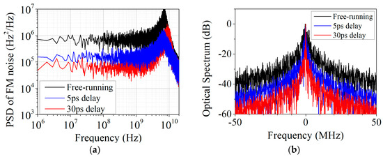
Figure 3.
(a) Calculated power spectrum density (PSD) of frequency modulation (FM) noise of mutually injection locked lasers with different delay time; (b) calculated optical spectrum of mutually injection locked lasers with different delay time. (κc = 2 × 10¹⁰/s, δ = 0).
Next, we consider the situation that delay time is increased to τd = 5 ns, an order of magnitude greater than 1/fRO. The frequency noise suppression is also valid for long delayed mutual coupling, although locking is found to be attainable only for weak coupling. The frequency noise in the time domain is calculated in Figure 4. For free-running lasers with 0.3 GHz detuning, the lasing frequency of either laser fluctuates with a standard deviation of 1.92 × 10⁶ Hz. When injection locking occurs, the standard deviation reduces to 1.36 × 10⁵ Hz, corresponding to a frequency noise suppression by a factor of 14.1.
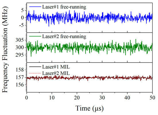
Figure 4.
Frequency fluctuation in the time domain of free-running and mutually injection locked lasers with long delay. (τd = 5 ns, κc = 5 × 10⁸/s, φp = 0, δ = 0.3 GHz).
Unlike the case of unidirectional injection locking, where the frequency noise of the slave laser can be improved by adopting a low frequency noise master laser [9,10], frequency noise reduction via mutual injection locking does not require the adoption of a low frequency noise laser, making it attractive for practical applications.
The third mechanism is the enhanced photon lifetime due to expanded cavity length. In the mutual coupling structure, a fraction of the photons are stored in the coupling path, which should be taken into consideration. When stable state is obtained at strong coupling, the entire system can be regarded as a compound resonator. Here, λ/4 shifted DFB lasers are employed to evaluate the change of photon lifetime. We extend the methods for photon lifetime determination in standard DFB lasers [33,34] to this compound cavity. Firstly, field distribution is derived by transfer matrix method. Then photon lifetime is derived by calculating the energy stored in the system and energy dissipated due to absorption and facet output. Typical field distribution of system with 8L coupling length is shown in Figure 5b. The equivalent mirror loss is αm = 44.6 cm−1 for a λ/4-shifted DFB with a typical coupling coefficient of κL = 1.5 (L = 500 μm), while the typical absorption loss is αi = 10 cm−1 [35]. As the coupling path is lengthened, equivalent mirror loss is reduced due to the expanded cavity length. Consequently, photon lifetime is increased as shown in Figure 5a. However, this trend slows down when αm is comparable to αi. The limit of photon lifetime is 10.8 ps determined by αi, five times longer than that of a solitary laser. Employing the low loss coupling region may reduce the laser linewidth further.
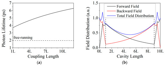
Figure 5.
(a) Photon lifetime in mutual coupling system with different coupling lengths; (b) field distribution in the mutual coupling system. (Laser length L = 500 μm, coupling coefficient κL = 1.5, absorption coefficient αi = 10 cm−1, injection ratio: 13.5%, group velocity vg = 9.29 × 10⁷ m/s.).
3. Experimental Study in Short Delay Regime
3.1. Devices
In order to investigate the linewidth characteristics of mutually locked lasers with short delay, monolithically integrated coupled DFB lasers were fabricated on identical epitaxial layers. Details about epitaxial structure are described in [36]. As is shown in Figure 6, the integrated device consists of two 500 μm grating regions and a grating-less coupling ridge waveguide. Electrical isolation between electrodes is formed by removing the top InGaAs ohmic contact layer via dry etching. Light from the device is coupled into a lensed fiber at cleaved facet end. In order to avoid reflection from the measurement system, an isolator is employed at the output fiber. On-chip mutually coupled lasers with 0.5, 2, 4 and 6 mm coupling regions are fabricated. The longest delay time is 64 ps, while fRO of the DFB laser is about 7 GHz, indicating these devices belong to the short delay regime.
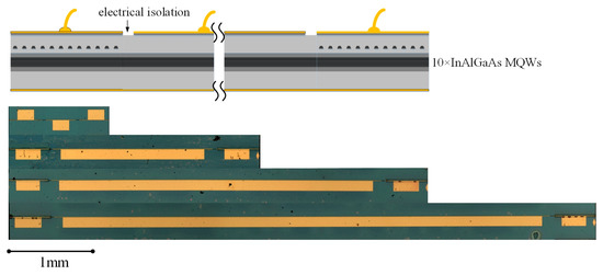
Figure 6.
Diagram and microscopy pictures of integrated mutually coupled devices.
3.2. Locking Condition
Stable single-mode lasing is a prerequisite to linewidth narrowing, so the locking condition of coupled DFB lasers is studied first. A series of dynamic behaviors emerge from the devices, including mutual injection locking, four wave mixing, periodic oscillation and chaos. The optical spectrum and intensity noise spectrum of these states are plotted in Figure 7a respectively. When the detuning between the sub-DFB lasers are relatively large, four wave mixing occurs. Increasing the coupling strength often results in chaos. Reducing the detuning towards zero will lead to periodic oscillation or mutual injection locking state.
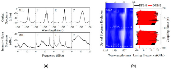
Figure 7.
Laser behavior in a 3 mm long integrated device. (a) Optical spectra and intensity noise spectra of mutually injection locked state (MIL), four wave mixing (F), periodic oscillation with relaxation oscillation frequency (R) and chaos (C); (b) left part: evolution of measured optical spectrum with coupling current; right part: simulated lasing frequency of sub-DFB lasers with different coupling phases φp.
It was found that the key parameter governing the laser behavior near zero detuning is the coupling phase. The lasing spectrum was recorded under different coupling currents to observe the evolution route. The corresponding map is plotted in the left part of Figure 7b. As the injection current in the coupling region increases from 59 to 82 mA, the laser spectrum evolves from single mode to multiple peaks spaced by relaxation oscillation frequency, corresponding to periodic oscillation. Increasing the coupling current further, the stable state occurs periodically with about a 12 mA interval. This phenomenon is also simulated in the right part of Figure 7b based on Equation (1). In the simulation, the variation of laser frequency is recorded as the coupling phase is swept from 0 to 2π. Stable lasing of both sub-DFB lasers with the same frequency occurs for the coupling phase close to integer number of π. Since the output power is only augmented by 0.7 dB as the coupling current varies, it is concluded that the coupling current is mainly responsible for phase adjustment and the 12 mA period recorded in our experiment may correspond to one π-shift of the coupling phase. Details for achieving mutual injection locking state is described in Appendix A.
3.3. Linewidth Narrowing
The measured linewidth of the 3 mm device under different coupling current is shown in Figure 8a. Injection current at the coupling region adjusts the coupling phase and compensates waveguide absorption simultaneously. When the current is below 50 mA, the absorption loss in the coupling region is too severe that coupling between the two sub-DFB lasers is negligible. Upon increasing the current further, stable mutual injection locking state is established at the discrete coupling current with appropriate coupling phase. Narrowed linewidth together with enhanced output power are obtained with increased coupling strength. The corresponding self-heterodyne signal obtained with 20-km-long fiber is shown in Figure 8b, revealing that the linewidth is narrowed by a factor of 8.2 at a coupling current of 103 mA. This technique is interesting since the linewidth performance can be improved without changing the epitaxial structure.
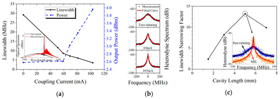
Figure 8.
(a) Linewidth and output power of a 3 mm length device at different coupling currents. Inset: FP modes emerge at high currents; (b) delayed self-heterodyne signals at different coupling currents; (c) linewidth narrowing factor of mutually coupled DFB lasers with different device lengths; Inset: the change of heterodyne spectrum from free-running to mutually injection locked state.
The heating effect of the coupling current induces a red shift of the gain spectrum, causing mismatch between the gain peak and the Bragg wavelength of the grating. Consequently, as is shown in the inset of Figure 8a, FP modes due to cleaved facets emerge at high currents, preventing an increase of the coupling current further. However, this proves that strong coupling between the two sub-DFB occurs. In addition, threshold reduction by 5 mA is also observed in the experiment due to optical injection, which also indicates that lasers are upon strong coupling. Future work on heat dissipation or optimization on epitaxial layers may improve device performance further. The linewidth-power product is reduced from 52.9 to 8.9 MHz∙mW, indicating that the linewidth narrowing is more than a result of increased output power.
As was analyzed in Section 2, longer coupling region can lead to better noise suppression. This prediction is confirmed in Figure 8c. More pronounced linewidth suppression tends to be achieved in lasers with longer coupling regions except for the device with 7 mm cavity length. The reason for the decreased linewidth narrowing factor of the 7 mm device is attributed to heat effect: It requires the highest current to compensate the absorption in the coupling region and suffers from heat induced gain peak shift most severely. The largest linewidth narrowing factor of ~13 is achieved in the 5 mm-long device, and the delayed self-heterodyne signals are shown in the inset of Figure 8c. Laser linewidth is narrowed to 0.74 MHz with 6.1 mW output power, corresponding to a linewidth-power product of 4.5 MHz∙mW.
3.4. Suppression of 1/f Noise
In the measurement above, the delayed self-heterodyne signal exhibits a Lorentzian line shape, indicating that the frequency noise is dominated by white noise. In the experiment, 1/f frequency noise arises in some devices probably induced by fabrication process [37]. As a result, the line shape transfers to Gaussian [38]. Nevertheless, it allows us to study the flicker noise characteristics in the proposed device structure. Gaussian linewidth and corresponding noise coefficient were extracted at different coupling currents, and the trend is shown in Figure 9. Flicker frequency noise is also suppressed in coupled DFB lasers and reduces with higher coupling strength. Since 1/f frequency noise results from surface or interface recombination [37] and is supposed to be independent of output power [39], mutual injection locking provides a new method to suppress 1/f noise.
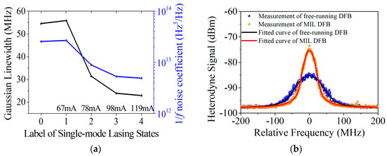
Figure 9.
(a) Dependence of 1/f frequency noise on coupling strength; (b) improvement of self-heterodyne signal from free-running to injection locked state labeled as 4.
3.5. Numerical Analysis of the Experiment
Since integrated coupled lasers with short delay can maintain injection locking under strong coupling, which is beneficial to linewidth reduction, linewidth narrowing should be attributed to the combination of the three mechanisms analyzed in Section 2. Figure 10 shows the simulation of the device with the 4 mm coupling region which exhibits the best linewidth narrowing performance in Figure 8c. In Section 2, the mutually coupled system is treated in two perspectives. Firstly, the system is regarded as a compound cavity under strong coupling. The enhanced photon lifetime estimated in Figure 5a leads to the linewidth reduction from 8.2 to 2.9 MHz in Figure 10. Secondly, the system is regarded as two coupled oscillators governed by coupled rate equations. The linewidth is suppressed from 8.2 MHz to 640 kHz considering the mutual phase locking and increased photon number. The order of linewidth narrowing factor agrees with the experiment. In combination with these effects, the integrated device should exhibit better performance. However, the injection current at the coupling region to compensate absorption generates extra noise source. Future research by adopting passive waveguide as the coupling region may achieve better linewidth performance.
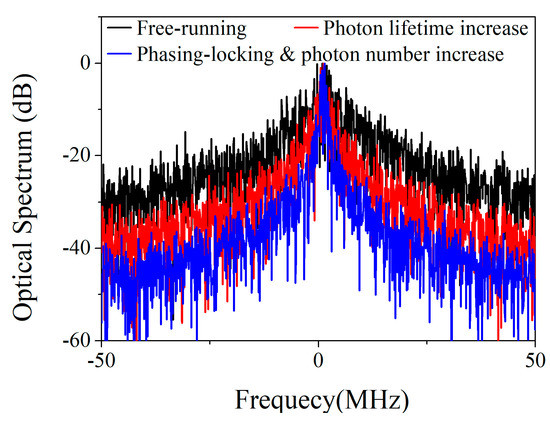
Figure 10.
Numerical simulation of linewidth performance of monolithically integrated mutually coupled laser under mutual injection locking. (τd = 40 ps, κc = 2 × 10¹⁰/s, δ = 0 GHz).
4. Experimental Study in Long Delay Regime
4.1. Experimental System
The experimental setup to investigate frequency noise of mutually coupled lasers with long delay is shown in Figure 11. Two DFB lasers without internal isolators in their packages are employed to implement mutual optical injection. They have similar characteristics and are mutually coupled through two 1 × 2 couplers (50/50), driven by ILX Lightwave 39425 current/TEC modules with 0.01 mA and 0.1 °C resolution. All fibers in the link, including laser pigtails, are polarization-maintaining fiber (PMF) to ensure polarization matching between the two lasers. Coupling strength is adjusted by an electrically controlled Micro-Electro-Mechanical System (MEMS) variable optical attenuator (VOA). An extra fiber cable is inserted before DFB#2 to adjust the coupling length. Frequency noise of the lasers are measured at Ports #1 and #2, where isolators (ISOs) are employed to prevent reflection from the measurement system. The delay time of the fiber link is on the order of ~10 ns, much longer than the time scale 1/fRO.

Figure 11.
Experimental setup for mutually coupled lasers in the long delay regime.
4.2. Locking Condition
The measured laser dynamics and locking map are plotted in Figure 12. The current of DFB#2 is fixed at 25 mA while the current of DFB#1 is adjusted to tune the frequency detuning between the two lasers at free running state. There are two differences between locking conditions in short and long delay regimes. First, the locking condition is insensitive to coupling phase. Coupling phase in the fiber link varies slowly over time since the refractive index and length changes with ambient temperature fluctuation. However, mutual injection locking remains, and a continuous locking region is mapped. Secondly, mutual injection locking only occurs at weak coupling in the long delay regime. In the high attenuation region, the locking range broadens as the coupling strength increases. For coupling strength higher than -37 dB, the locked region breaks into two narrow branches and then disappears. The process to establish mutual injection locking state is described in Appendix A in detail.
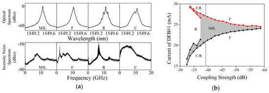
Figure 12.
(a) Optical spectra and intensity noise spectra of mutually injection locked state (MIL), F: four wave mixing (F), periodic oscillation with relaxation frequency (R) and chaos (C); (b) locking map of mutually coupled DFB lasers with long delay.
4.3. Linewidth Narrowing
Linewidth narrowing of the mutually injection locked DFB lasers is confirmed by both local oscillator (LO) heterodyne and delayed self-heterodyne. For LO heterodyne in Figure 13a, the recorded beat signal is the convolution between the LO laser (TSL-210V, Santec, Komaki, Japan) and the laser being tested, and details in spectrum can be resolved due to better resolution than optical spectrum analyzer. The heterodyne spectra of free-running (FR) DFB lasers exhibit a Lorentzian shape with megahertz level linewidth. When mutual injection locking is achieved, the LO-heterodyne spectra of both lasers are narrowed significantly.
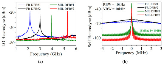
Figure 13.
(a) Linewidth narrowing phenomenon measured by the local oscillator (LO)-heterodyne method; (b) linewidth narrowing phenomenon measured by delayed self-heterodyne method.
The delayed self-heterodyne spectra acquired by electrical spectrum analyzer are plotted in Figure 13b with 2 km (10 μs) fiber delay line. Compared with the free-running ones, the heterodyne spectra of injection locked lasers transform to the correlated type and exhibit ultra-high coherence features: (1) a delta-function-like RF carrier stands out at the central frequency; (2) notches spaced by 100 kHz emerge on the signal wings, corresponding to the reciprocal of the fiber delay time in the heterodyne measurement.
4.4. Frequency Noise Reduction
The PSD of FM noise of locked DFB lasers under different coupling strength and length are shown in Figure 14, obtained by delayed self-heterodyne measurement with 2 km fiber. The peaks at multiples of 100 kHz (reciprocal of delay time) are artefacts caused by converting the measured RF phase noise to laser frequency noise [17,40]. A strategy in [41] was employed to partially overcome these artefacts. The measured PSD of FM noise spectra suffer from 1/f n noise in low frequency range and white noise dominates above 100 kHz. Increasing the coupling strength leads to reduction of both types of frequency noises, and two lasers exhibit similar performance. Increasing the coupling length, i.e., the coupling delay, is also helpful for frequency noise reduction. The lowest white noise achieved in the system is about S0 = 20 Hz2/Hz, corresponding to an intrinsic linewidth of Δνint = πS0 = 62.8 Hz.
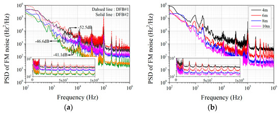
Figure 14.
(a) PSD of FM noise of injection locked lasers under different coupling strength; (b) PSD of FM noise of injection locked lasers with different coupling length. Insets: a magnified view of the white noise. (Peaks at multiples of 100 kHz are measurement artefacts of delayed self-heterodyne measurement.).
4.5. Numerical Analysis of the Experiment
In our experiment, the coupling strength is estimated to be only −40 dB. Consequently, photon number increase and photon lifetime enhancement do not contribute much to linewidth reduction. On the other hand, the mutual phase-locking mechanism is believed to be responsible for such pronounced linewidth reduction in a mutually coupled system with weak coupling and long delay. Figure 15 estimates the linewidth narrowing performance of lasers coupled in the long delay regime by taking mutual phase-locking mechanism into consideration. The delay time is set as 50 ns which corresponds to the 10-m-long coupling fiber adopted in Figure 14b. The intrinsic linewidth is suppressed from 2.2 MHz in free-running state to 103.5 Hz upon mutual injection locking. The simulation matches the improvement of coherence indicated by self-heterodyne signals shown in Figure 13b and the intrinsic linewidth achieved in Figure 14b.
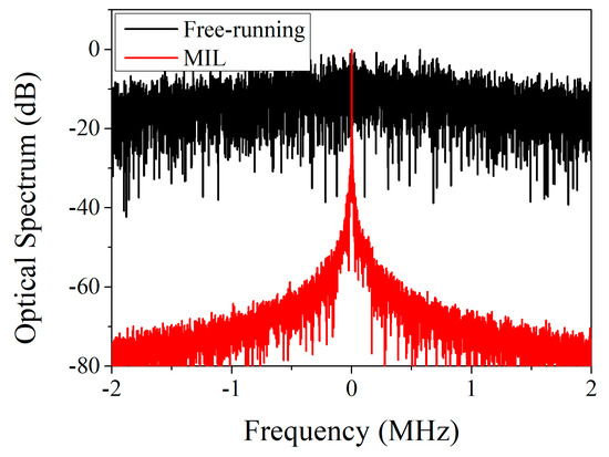
Figure 15.
Numerical simulation of linewidth performance of mutually injection locked laser based on fiber link. (τd =50 ns, κc= 5 × 10⁸/s, δ = 0 GHz).
5. Discussion
The proposed linewidth narrowing scheme based on mutual injection locking is a different method compared with traditional approaches such as self-injection or external cavity lasers. For narrow linewidth operation, self-injection or external cavity increase the photon lifetime via low loss external cavity. The lasing mode is a result of multiple mode selection components. For example, in classical Littrow [42] or Littman [43] configuration, the mode is selected by grating and FP cavity. The Vernier effect in multiple ring resonators [11,12,13,16] is also employed to realize single mode selection. However, stable single-mode lasing state in mutual injection locking is a result of coupling between two oscillators [30,31], which can lase independently without mutual optical injection. Hence the proposed approach can be simply implemented by coupling lasers through an optical path. Moreover, mutual phase-locking in mutual injection locking provides a unique mechanism for linewidth narrowing. The intrinsic linewidth of lasers mutually coupled by fiber link is in the order of 100 Hz, narrower than ~kHz obtained in fiber-link based self-injection configuration [15,16]. In this work, frequency noise reduction mechanisms, dependence on coupling parameters and locking conditions are investigated theoretically and experimentally, demonstrating mutual injection locking as a simple and practical method to compress laser linewidth.
Although linewidth narrowing of mutually injection locked lasers is achieved in both short and long delay regimes, laser behavior shows different rules. The laser in the short delay regime allows strong coupling and the laser state exhibits a strong dependence on coupling phase. Linewidth narrowing is attributed to the combined effect of the three mechanisms analyzed in Section 2. While, stable injection locking only occurs at weak coupling in the long delay regime and it is insensitive to coupling phase. Mutual phase-locking is considered the main factor for frequency noise suppression.
6. Conclusions
The improvement of linewidth performance of mutually injection locked semiconductor lasers is investigated, and there have been relatively few reports on this aspect. The locking condition and the influence of system parameters on frequency noise is studied experimentally in both short and long delay regimes, demonstrating mutual injection locking as a practical approach for linewidth reduction. The linewidth performance of mutually injection locked lasers is found to improve with increasing coupling length and coupling strength. For the short-delayed integrated lasers, a linewidth narrowing factor of 13 is demonstrated and 0.74 MHz linewidth is achieved, while the intrinsic linewidth is reduced from megahertz to 62.8 Hz for the long-delayed lasers coupled by fiber link.
Compared with unidirectional injection, laser linewidth is narrowed without the need of a low frequency noise master laser. In comparison with self-injection or external cavity, the proposed approach can be realized simply by an optical coupling path. In addition, mutual phasing-locking provides a special mechanism for linewidth narrowing of mutually coupled lasers. In combination of advanced integration techniques, the proposed method can be employed for narrow linewidth semiconductor lasers which have important applications in coherent optical communication, atomic sensing and microwave photonics.
Author Contributions
Conceptualization, B.X. and Y.L.; methodology, W.M. and C.S.; validation, J.W., Z.H., L.W. and H.L.; investigation, W.M.; resources, X.K., Y.H. and C.S.; data curation, J.Y.; writing—original draft preparation, W.M.; writing—review and editing, M.W., C.S. and B.X.; supervision, Y.L.
Funding
This research was funded by National Key Research and Development Plan of China (2017YFA0205800, 2018YFB0406700); Science Challenge Project (Grant No. TZ2016003); National Basic Research Program of China (Grant No. 2015CB351900); National Natural Science Foundation of China (Grant No. 51561165012, 51561145005, 61574082, 61621064, 61822404, 61875104); Tsinghua University Initiative Scientific Research Program (Grant No. 20161080068, 20161080062, 2015THZ02-3); China Postdoctoral Science Foundation (Grant No. 2018M640129) and Collaborative Innovation Centre of Solid-State Lighting and Energy-Saving Electronics.
Conflicts of Interest
The authors declare no conflict of interest.
Appendix A
In the experiment, lasers are controlled by LDC-3900 equipped with LCM-39425 modules (ILX Lightwave, Irvine, USA) with 0.01 mA and 0.1 °C resolution. Mutual injection locking between DFB lasers is achieved with near zero detuning.
The current tuning coefficient of monolithically integrated coupled DFB lasers for study of short delay regime is about 5.1 GHz/mA. Under the weak coupling condition, the integrated device will operate at F state shown in Figure 7a. The frequency of the beat signal in the intensity noise spectrum corresponds to the detuning between the sub-DFB lasers. Tuning the current of one laser while maintaining that of the other so that beat signal move towards 0 Hz will lead to near zero detuning. Then, the coupling current is increased to adjust coupling strength and coupling phase, and the locking state will emerge periodically as is shown in Figure 7b. Since the sub-DFB lasers are fabricated on the same epitaxial wafer, their characteristics are similar, and the mutual injection locking is established at similar current values.
In the long-delayed experiment based on fiber link, two DFB lasers with similar characteristics are adopted. Under weak coupling, the laser will stay in F state shown in Figure 12a, where the beat signal in intensity spectrum corresponds to the detuning between the two lasers. The process to achieve zero detuning is similar to that for integrated devices. The current tuning coefficient is about 1.75 GHz/mA for lasers used in long-delay experiments. The coupling strength is adjusted by a voltage-controlled MEMS variable optical attenuator. Increase the coupling strength will lead to broader locking bandwidth and the corresponding locking map is depicted in Figure 12b.
The output light is fed into a power meter, optical spectrum analyzer, electrical spectrum analyzer connected to photodetector, delayed self-heterodyne system to measure the output power, optical spectrum, intensity noise spectrum, linewidth or frequency noise, respectively.
References
- Ip, E.; Lau, A.P.T.; Barros, D.J.F.; Kahn, J.M. Coherent detection in optical fiber systems. Opt. Express 2008, 16, 753–791. [Google Scholar] [CrossRef] [PubMed]
- Olmedo, M.I.; Pang, X.; Schatz, R.; Ozolins, O.; Louchet, H.; Zibar, D.; Jacobsen, G.; Monroy, I.T.; Popov, S. Effective linewidth of semiconductor lasers for coherent optical data links. Photonics 2016, 3, 39. [Google Scholar] [CrossRef]
- Kakkar, A.; Navarro, J.R.; Schatz, R.; Pang, X.; Ozolins, O.; Udalcovs, A.; Louchet, H.; Popov, S.; Jacobsen, G. Laser frequency noise in coherent optical systems: Spectral regimes and impairments. Sci. Rep. 2017, 7. [Google Scholar] [CrossRef] [PubMed]
- Camparo, J.C.; Coffer, J.G. Conversion of laser phase noise to amplitude noise in a resonant atomic vapor: The role of laser linewidth. Phys. Rev. A 1999, 59, 728–735. [Google Scholar] [CrossRef]
- Kitching, J.; Knappe, S.; Donley, E.A. Atomic Sensors-a Review. IEEE Sens. J. 2011, 11, 1749–1758. [Google Scholar] [CrossRef]
- Sigrist, M.W.; Bartlome, R.; Marinov, D.; Rey, J.M.; Vogler, D.E.; Waechter, H. Trace gas monitoring with infrared laser-based detection schemes. Appl. Phys. B-Lasers Opt. 2008, 90, 289–300. [Google Scholar] [CrossRef]
- Lu, Y.; Zhu, T.; Chen, L.; Bao, X. Distributed Vibration Sensor Based on Coherent Detection of Phase-OTDR. J. Lightwave Technol. 2010, 28, 3243–3249. [Google Scholar]
- Dale, E.; Liang, W.; Eliyahu, D.; Savchenkov, A.A.; Ilchenko, V.S.; Matsko, A.B.; Seidel, D.; Maleki, L. Ultra-narrow line tunable semiconductor lasers for coherent LIDAR applications. In Proceedings of the Imaging and Applied Optics, Seattle, WA, USA, 13–17 July 2014. paper JTu2C.3. [Google Scholar]
- Bondiou, M.; Gabet, R.; Stephan, G.M.; Besnard, P. Linewidth of an optically injected semiconductor laser. J. Opt. B Quantum Semiclass. Opt. 2000, 2, 41–46. [Google Scholar] [CrossRef]
- Wang, Y.; Kasai, K.; Yoshida, M.; Nakazawa, M. A 6 kHz linewidth, injection-locked LD using a master erbium fiber laser. In Proceedings of the OptoElectronics and Communication Conference, Melborne, VIC, Australia, 6–10 July 2014; pp. 417–418. [Google Scholar]
- Komljenovic, T.; Liang, L.; Chao, R.; Hulme, J.; Srinivasan, S.; Davenport, M.; Bowers, J.E. Widely-Tunable Ring-Resonator Semiconductor Lasers. Appl. Sci. 2017, 7, 32. [Google Scholar] [CrossRef]
- Kobayashi, N.; Sato, K.; Namiwaka, M.; Yamamoto, K.; Watanabe, S.; Kita, T.; Yamada, H.; Yamazaki, H. Silicon photonic hybrid Ring-Filter external cavity wavelength tunable lasers. J. Lightwave Technol. 2015, 33, 1241–1246. [Google Scholar] [CrossRef]
- Zhu, Y.; Zhu, L. Narrow-linewidth tunable external cavity dual-band diode lasers through InP/GaAs-Si3N4 hybrid integration. Opt. Express 2019, 27, 2354–2362. [Google Scholar] [CrossRef] [PubMed]
- Stern, B.; Ji, X.; Dutt, A.; Lipson, M. Compact narrow-linewidth integrated laser based on a low-loss silicon nitride ring resonator. Opt. Lett. 2017, 42, 4541–4544. [Google Scholar] [CrossRef]
- Kasai, K.; Nakazawa, M.; Ishikawa, M.; Ishii, H. 8 kHz linewidth, 50 mW output, full C-band wavelength tunable DFB LD array with self-optical feedback. Opt. Express 2018, 26, 5675–5685. [Google Scholar] [CrossRef] [PubMed]
- Yu, L.; Lu, D.; Pan, B.; Zhang, L.; Guo, L.; Li, Z.; Zhao, L.J. Widely Tunable Narrow-Linewidth Lasers Using Self-Injection DBR Lasers. IEEE Photonic Technol. Lett. 2015, 27, 50–53. [Google Scholar] [CrossRef]
- Lewoczko-Adamczyk, W.; Pyrlik, C.; Haeger, J.; Schwertfeger, S.; Wicht, A.; Peters, A.; Erbert, G.; Traenkle, G. Ultra-narrow linewidth DFB-laser with optical feedback from a monolithic confocal Fabry-Perot cavity. Opt Express 2015, 23, 9705–9709. [Google Scholar] [CrossRef] [PubMed]
- Liang, W.; Ilchenko, V.S.; Eliyahu, D.; Savchenkov, A.A.; Matsko, A.B.; Seidel, D.; Maleki, L. Ultralow noise miniature external cavity semiconductor laser. Nat. Commun. 2015, 6. [Google Scholar] [CrossRef] [PubMed]
- Liu, D.; Sun, C.; Xiong, B.; Luo, Y. Nonlinear dynamics in integrated coupled DFB lasers with ultra-short delay. Opt. Express 2014, 22, 5614–5622. [Google Scholar] [CrossRef]
- Soriano, M.C.; Garcia-Ojalvo, J.; Mirasso, C.R.; Fischer, I. Complex photonics: Dynamics and applications of delay-coupled semiconductors lasers. Rev. Mod. Phys. 2013, 85, 421–470. [Google Scholar] [CrossRef]
- Heil, T.; Fischer, I.; Elsasser, W.; Mulet, J.; Mirasso, C.R. Chaos synchronization and spontaneous symmetry-breaking in symmetrically delay-coupled semiconductor lasers. Phys. Rev. Lett. 2001, 86, 795–798. [Google Scholar] [CrossRef] [PubMed]
- Wunsche, H.J.; Bauer, S.; Kreissl, J.; Ushakov, O.; Korneyev, N.; Henneberger, F.; Wille, E.; Erzgraber, H.; Peil, M.; Elsasser, W.; Fischer, I. Synchronization of delay-coupled oscillators: A study of semiconductor lasers. Phys. Rev. Lett. 2005, 94. [Google Scholar] [CrossRef] [PubMed]
- Sun, C.; Liu, D.; Xiong, B.; Luo, Y.; Wang, J.; Hao, Z.; Han, Y.; Wang, L.; Li, H. Modulation characteristics enhancement of monolithically integrated laser diodes under mutual injection locking. IEEE J. Sel. Top. Quant. 2015, 21, 628–635. [Google Scholar] [CrossRef]
- Huang, J.; Sun, C.; Xiong, B.; Luo, Y. Y-branch integrated dual wavelength laser diode for microwave generation by sideband injection locking. Opt. Express 2009, 17, 20727–20734. [Google Scholar] [CrossRef] [PubMed]
- Chen, Z.; Hou, J.; Zhou, P.; Jiang, Z. Mutual injection-locking and coherent combining of two individual fiber lasers. IEEE J. Quantum Electron. 2008, 44, 515–519. [Google Scholar] [CrossRef]
- Brewer, L.R. Highly Coherent Injection-Locked Laser Diode-Arrays. Appl. Opt. 1991, 30, 317–320. [Google Scholar] [CrossRef] [PubMed]
- Kurtz, R.M.; Pradhan, R.D.; Tun, N.; Aye, T.M.; Savant, G.D.; Jannson, T.P.; DeShazer, L.G. Mutual injection locking: A new architecture for high-power solid-state laser arrays. IEEE J. Sel. Top. Quant. 2005, 11, 578–586. [Google Scholar] [CrossRef]
- Ma, W.; Xiong, B.; Ke, X.; Sun, C.; Luo, Y.; Hao, Z.; Wang, J.; Han, Y.; Wang, L.; Li, H. Novel linewidth narrowing scheme of DFB lasers based on integrated mutual injection locking. In Proceedings of the Asia Communications and Photonics Conference, Guangzhou, China, 10–13 November 2017. paper M1D.4. [Google Scholar]
- Ruiz-Oliveras, F.R.; Pisarchik, A.N. Synchronization of semiconductor lasers with coexisting attractors. Phys. Rev. E 2009, 79. [Google Scholar] [CrossRef] [PubMed]
- Erzgraber, H.; Krauskopf, B.; Lenstra, D. Compound laser modes of mutually delay-coupled lasers. SIAM J. Appl. Dyn. Syst. 2006, 5, 30–65. [Google Scholar] [CrossRef]
- Erzgraber, H.; Lenstra, D.; Krauskopf, B.; Wille, E.; Peil, M.; Fischer, I.; Elsasser, W. Mutually delay-coupled semiconductor lasers: Mode bifurcation scenarios. Opt. Commun. 2005, 255, 286–296. [Google Scholar] [CrossRef]
- Fatadin, I.; Ives, D.; Wicks, M. Numerical simulation of intensity and phase noise from extracted parameters for CW DFB lasers. IEEE J. Quantum Electron. 2006, 42, 934–941. [Google Scholar] [CrossRef]
- Topic, V.J.; Crnjanski, J.V.; Krstic, M.M.; Totovic, A.R.; Gvozdic, D.M. Analytical method for calculation of the photon lifetime and external coupling coefficient in index-coupled phase-shifted DFB lasers. IEEE J. Sel. Top. Quant. 2015, 21. [Google Scholar] [CrossRef]
- Zheng, W.; Taylor, G.W. Determination of the photon lifetime for DFB lasers. IEEE J. Quantum Electron. 2007, 43, 295–302. [Google Scholar] [CrossRef]
- Coldren, L.A.; Corzine, S.W.; Mashanovitch, M.L. Dynamic Effect. In Diode Lasers and Photonic Integrated Circuits, 2nd. ed; John Wiley and Sons: Hoboken, NJ, USA, 2012; pp. 260–261. [Google Scholar]
- Sun, C.; Xiong, B.; Wang, J.; Cai, P.; Xu, J.; Huang, J.; Yuan, H.; Zhou, Q.; Luo, Y. Fabrication and packaging of 40-Gb/s AlGaInAs multiple-quantum-well electroabsorption modulated lasers based on identical epitaxial layer scheme. J. Lightwave Technol. 2008, 26, 1464–1471. [Google Scholar] [CrossRef]
- Hakimi, R.; Amann, M.C. Reduction of 1/f carrier noise in InGaAsP/InP heterostructures by sulphur passivation of facets. Semicond. Sci. Technol. 1997, 12, 778–780. [Google Scholar] [CrossRef]
- Mercer, L.B. 1/F frequency noise effects on self-heterodyne linewidth measurements. J. Lightwave Technol. 1991, 9, 485–493. [Google Scholar] [CrossRef]
- Kikuchi, K. Effect of 1/f-type fm noise on semiconductor-laser linewidth residual in high-power limit. IEEE J. Quantum Electron. 1989, 25, 684–688. [Google Scholar] [CrossRef]
- Camatel, S.; Ferrero, V. Narrow linewidth CW laser phase noise characterization methods for coherent transmission system applications. J. Lightwave Technol. 2008, 26, 3048–3055. [Google Scholar] [CrossRef]
- Zhou, Q.; Qin, J.; Xie, W.; Liu, Z.; Tong, Y.; Dong, Y.; Hu, W. Dynamic frequency-noise spectrum measurement for a frequency-swept DFB laser with short-delayed self-heterodyne method. Opt. Express 2015, 23, 29245–29257. [Google Scholar] [CrossRef] [PubMed]
- Hawthorn, C.J.; Weber, K.P.; Scholten, R.E. Littrow configuration tunable external cavity diode laser with fixed direction output beam. Rev. Sci. Instrum. 2001, 72, 4477–4479. [Google Scholar] [CrossRef]
- Harvey, K.C.; Myatt, C.J. External-cavity diode-laser using a grazing-incidence diffraction grating. Opt. Lett. 1991, 16, 910–912. [Google Scholar] [CrossRef] [PubMed]
© 2019 by the authors. Licensee MDPI, Basel, Switzerland. This article is an open access article distributed under the terms and conditions of the Creative Commons Attribution (CC BY) license (http://creativecommons.org/licenses/by/4.0/).