Article

Energy Storage System Controller Design for Suppressing Electromechanical Oscillation of Power Systems

1
School of Mechanical Engineering, Southeast University, Nanjing 210009, China
2
China Electric Power Research Institute Company Ltd., Nanjing 210003, China
3
College of Electrical and Information Engineering, Hunan University of Technology, Zhuzhou 412000, China
4
College of Electrical and Information Engineering, Shaanxi University of Science & Technology, Xi’an 710021, China
*
Author to whom correspondence should be addressed.
Appl. Sci. 2019, 9(7), 1329; https://doi.org/10.3390/app9071329
Submission received: 10 February 2019 / Revised: 9 March 2019 / Accepted: 11 March 2019 / Published: 29 March 2019
(This article belongs to the Section Electrical, Electronics and Communications Engineering)

Abstract

:

Featured Application

Suppressing Electromechanical Oscillation of Power Systems for Energy Storage Systems.

Abstract

Through the feedback of the rotor speed and/or the grid frequency, an energy storage system (ESS) can effectively suppress the electromechanical oscillation of a power system. This paper proposes a novel control strategy and controller parameter design method for ESSs to achieve the desired performance of oscillation suppression, including smaller frequency and rate of change of frequency (ROCOF) deviation than their threshold values. Firstly, a dynamic model of the electromechanical time scale of a synchronous generator dominated power system with ESS was established. Then, based on the dynamic model and the electric torque analysis method, the mechanism of an ESS with the feedback signal of the rotor speed to suppress the electromechanical oscillation was investigated. Finally, the controller parameter design method for the ESS was developed to achieve the desired performance of oscillation suppression. With the help of the well-designed ESS, the electromechanical oscillation of a synchronous generator dominated power system can be effectively suppressed in shorter transient response times, and the grid frequency deviation and the ROCOF can be limited to below their threshold values. The simulation results also verify the effectiveness of the proposed control strategy and the controller parameter design method.

1. Introduction

With the continuous expansion of power systems, the structure of the power system is becoming more and more complex, and technological disturbances are gradually increasing with the growth of renewable energy. The traditional electromechanical oscillation of the synchronous generator (SG) dominated power system is becoming more frequent and complicated, which seriously affects the safe and stable operation of power grid [1,2,3].
The analysis and control of power oscillations on the electromechanical time scale has always been a hot issue in power systems, and scholars at home and abroad have undertaken extensive research in this field. Traditional oscillation suppression methods include power system stabilizers (PSS) and flexible AC transmission systems (FACTS), which can effectively suppress the electromechanical oscillation to a certain extent. In recent years, power systems have taken on higher requirements for grid operation, and traditional methods cannot meet the system operation requirements in terms of suppression response speed and the control of low ultralow frequency oscillation [4,5]. With the development of power electronics, FACTS devices have been widely used in the power grid. The rapid and effective suppression of grid power oscillation can be achieved with the help of fast-response FACTS devices and advanced control strategies. The technical methods of FACTS devices to suppress power oscillation can be roughly divided into active power-based methods and reactive power-based methods. In [6], the electromechanical oscillation of a power system is suppressed by controlling the active power of the ESS. The ESS can directly and effectively suppress grid power oscillation, showing excellent technical performance. However, when the power system is large, the capacity of ESSs will increase dramatically, so the cost of pure active power-based methods is very high. To overcome the cost issue, distributed generation, such as wind power and photovoltaic power, were utilized to suppress the power oscillations in [7,8,9], however, distributed generation has great volatility and randomness, and works in the maximum power tracking mode, so it is difficult to effectively suppress the electromechanical oscillation. Compared with pure active power-based methods, the pure reactive power-based scheme shows great cost advantages. In [10], a control strategy based on a genetic algorithm was proposed, which uses the unified power flow controller to suppress the oscillation. In [11], a flexible transmission system is used to equivalently change the impedance of a power system, which can improve the system damping characteristics and suppress power oscillation. By controlling the output reactive power of STATCOM, the oscillation suppression can be indirectly realized [12,13], which makes full use of the fast response of STATCOM. In [14,15], the physical mechanism of STATCOM suppression of power grid electromechanical oscillation was investigated. The effects of different control modes on power oscillation suppression were also studied in terms of system inertia, damping, and synchronization effects. By optimizing the inertia and damping parameters of the virtual synchronous generator, the transient response process of the power system can be effectively controlled [16,17,18]. However, the existing oscillation suppression devices adopt control schemes with fixed parameters, which cannot automatically adjust the system inertia and damping according to the operating status of the specific power system, so better oscillation suppression performance cannot be achieved.
Therefore, this paper fully combines the cost advantage of reactive power-based methods and the technical advantage of active power-based methods, so that the ESS can work mainly in the reactive power suppression mode, and its active power output is mainly used to compensate the power loss and to ensure DC side voltage stability. At the same time, a certain amount of active power support is also provided to the grid during the violent oscillation period to ensure the fault ride-through capability of the power system, and the ESS cost is reduced as much as possible under the premise of achieving the expected suppression effect. In addition, by real-time optimization of the ESS controller’s parameters, online regulation of the equivalent inertia and damping of the power system is realized, and the dynamic performance of oscillation suppression is improved, ensuring that the grid oscillation is restrained at the fastest speed under the premise of satisfying the constraints of smaller frequency and rate of change of frequency (ROCOF) deviation below their threshold values.
This paper is organized as follows. The mechanism of using the ESS to suppress electromechanical oscillation is first introduced in Section 2. In Section 3, the electromechanical oscillation process of SG dominated power systems is analyzed in detail and the basic principle of electromechanical oscillation control is also investigated. In Section 4, the modified control strategy is proposed to improve the dynamic performance of oscillation suppression and the controller parameter design method of the modified ESS control strategy is also proposed. In Section 5, a large number of comparative experiments are carried out and the experimental results verify the effectiveness of the proposed control strategy and its controller parameter design method for ESSs. Finally, the main conclusions of this paper are summarized in Section 6.

2. Mechanism of Using the ESS to Suppress Electromechanical Oscillation

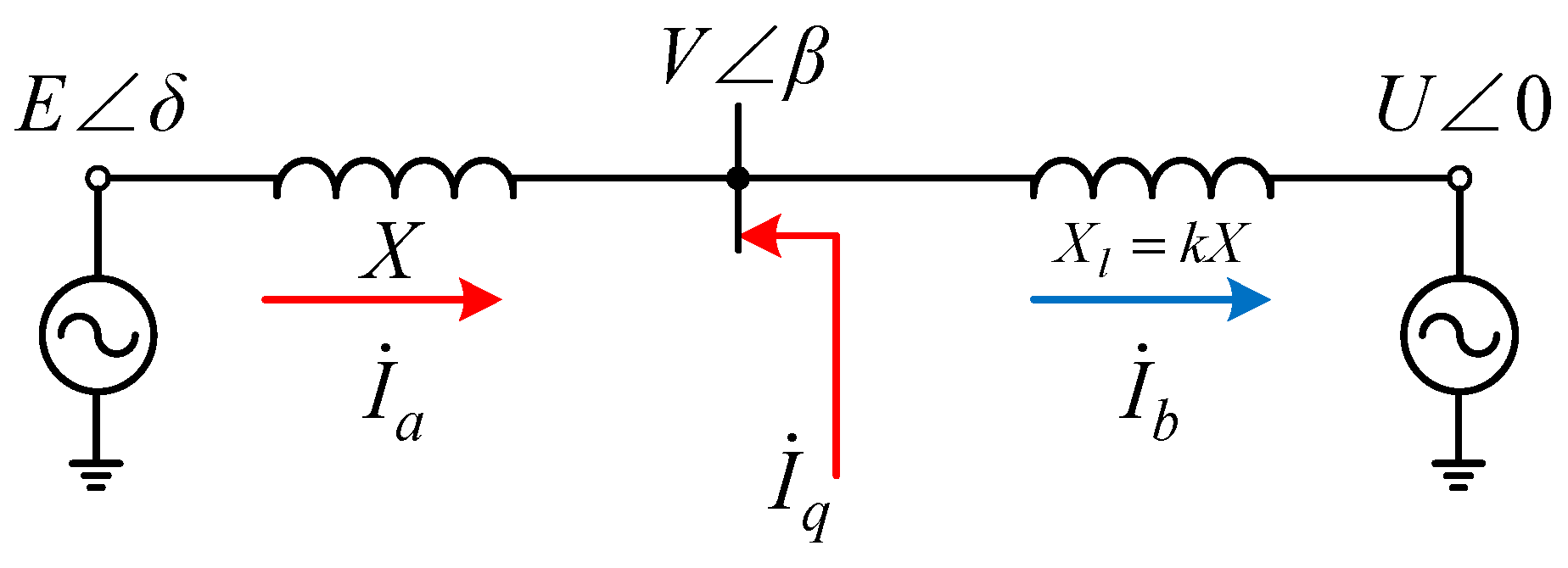
2.1. Equivalent Model of an SG Dominated Power System with ESS

As shown in Figure 1, the regional power grid is described by an equivalent synchronous generator (SG) and connected to the utility grid with an approximately infinite capacity. In order to achieve better performance of oscillation suppression, the ESS is connected to the power system at the center of the transmission line [19,20]. In Figure 1, udc is the DC side voltage of ESS. E, V, and U are, respectively, the voltages of the equivalent SG, the connection point, and the utility grid; ZT, Zl, and Z are the equivalent impedances of the transmission lines; Pm and Pe respectively represent the input mechanical power and the output electromagnetic power of the equivalent SG.
When the power system operates steadily, the input and output power of the equivalent SG are balanced, and the power grid frequency can be stably maintained. When the power grid is disturbed and the rotor power is unbalanced, electromechanical oscillation occurs in the power system. Since the inertia of the SG is large, the electromechanical oscillation period after the system disturbance is also longer. When electromechanical oscillation occurs in the power system, the rotor speed and/or the power angle of the SG can be fed back to the ESS. An ESS with a PID (or PD) controller can equivalently change the inertia effect, damping capacity, and synchronization of the power system, thereby modifying the electromechanical oscillation [14].
According to the conclusion of the research in [19], when the ESS suppresses the electromechanical oscillation of the power grid, there are two main types of feedback signals, the power angle of the SG (or the transmission line power) and the rotor speed of the SG (or the grid frequency). In view of the fact that the power angle of the SG is hard to measure, and the ESS with a PD controller cannot affect the system inertia when the power angle is fed back, the ESS with the feedback signal of rotor speed is adopted in this paper, as shown in Figure 2. U*dc is the rated value of the DC side voltage of the ESS, ω0 is the rated rotor frequency, and the PLL of the grid phase detection module adopts the synchronous reference frame-based open-loop phase locking scheme (SRF-OLPL) [21,22].

2.2. Mechanism Analysis of ESS-Based Oscillation Suppression

In order to analyze the mechanism of ESS suppression of electromechanical oscillation, the system equivalent model shown in Figure 1 is firstly simplified on the electromechanical time scale, as shown in Figure 3. It should be noted that in order to fully combine the cost advantage of reactive power-based methods and the technical advantage of active power-based schemes, this paper allows the ESS to work in the reactive power-based suppression mode. Its active power is mainly used to compensate the power loss of the ESS itself to ensure the DC side voltage stability. Since the active power required to maintain the DC side voltage stability is small and negligible, the control strategy shown in Figure 2 can minimize the ESS cost while achieving the desired suppression performance. Therefore, the electromechanical model of the ESS shown in Figure 3 can be viewed as a reactive current source. In addition, the voltage vector diagram of the simplified system model on the electromechanical time scale is shown in Figure 4. X and Xl represent the equivalent reactance, and Iq is the reactive current injected by the ESS to the grid.
When analyzing the stability of an SG-based power system, the linearized model of the swing equation of SG is usually used, namely:
{ d Δ δ d t = ω 0 Δ ω T J d Δ ω d t = Δ P m Δ P e ,
To investigate the physical mechanism of dynamic stability of a power system, the electric torque analysis method adopts the equivalent inertia coefficient TJ, the synchronization coefficient TS, and the damping coefficient TD to characterize the inertia, synchronization, and damping effects of the SG-based system, respectively [15]. Assume the input mechanical power of the equivalent SG is constant, that is ΔPm = 0, (1) can be rewritten as the following standard equation:
{ d Δ δ d t = ω 0 Δ ω T J d Δ ω d t = T S Δ δ T D Δ ω ,
According to the above models on the electromechanical time scale, the output electromagnetic power of the equivalent SG in Figure 1 can be expressed as:
P e = E V X sin α = E V X E sin δ ( 1 + k ) V + k X I q ,
Simplifying (3) and linearizing it at the steady-state point of the power system, the intermediate variable V can be eliminated, and we will have:
Δ P e = K g Δ δ K q Δ I q ,
where, Kg is the synchronization coefficient of the power system itself, which characterizes the synchronization ability of the power system. Kq is the control coefficient of the ESS, which characterizes the ability of the ESS to control the dynamic characteristics of the power system, and the expressions of Kg and Kq are respectively (the subscript “0” denotes the steady-state point value)
K g = X ( P e 0 V 0 ) 2 ( k X 2 I q 0 E 2 V 0 sin δ 0 k 1 + k ) + cos δ 0 sin δ 0 P e 0 ,
K q = X E 2 ( P e 0 V 0 ) 2 k X sin δ 0 ( V 0 k 1 + k ) ,
When the ESS utilizes the feedback signal of the rotor speed of the SG and adopts the PID controller, its output current Iq is:
I q = ( K p + K i s + s K d ) Δ ω ,
where, Kp, Ki, and Kd are the corresponding parameters of the PID controller of the ESS.
Linearizing (7) and taking (2) into account, we will have:
Δ I q = K p Δ ω K i Δ δ s K d Δ ω ,
Substituting (8) into (4), the output electromagnetic power of the equivalent SG that is affected by the ESS can be obtained:
Δ P e = ( K g + K i K q ) Δ δ + ( K p + s K d ) K q Δ ω ,
Substituting (9) into (1) and considering ΔPm = 0, the swing equation of the equivalent SG that is affected by the ESS can be converted into:
( 2 H + K q K d ) d Δ ω d t = ( K g + K q K i ) Δ δ ( D + K q K p ) Δ ω ,
By comparing (10) with (2), it can be seen that when the rotor speed of the SG is fed back and the PID controller is adopted, the controller parameters will simultaneously and equivalently change the inertia coefficient, the synchronization coefficient, and the damping coefficient of the SG-based power system at the same time, where the P controller mainly affects the damping ability of the system; the I controller mainly affects the synchronization ability of the system; the D controller mainly affects the system inertia, and:
{ T D = D + K q K p T S = K g + K q K i T J = 2 H + K q K d ,
Equation (11) shows that the ESS in the oscillation suppression mode can equivalently change the inertia effect, damping capacity and synchronization ability of the power system, thereby affecting the oscillation amplitude, the oscillation period, and the oscillation time. However, if the ESS adopts a control scheme with fixed parameters, it cannot automatically adjust the system inertia and damping ability according to the operating state of the SG-dominated power system, and thus better oscillation suppression performance cannot be achieved.

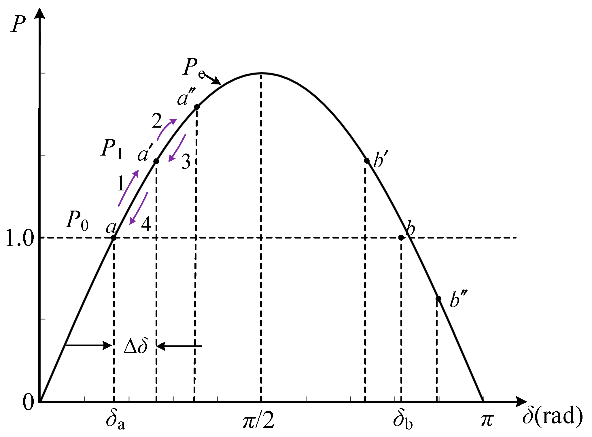
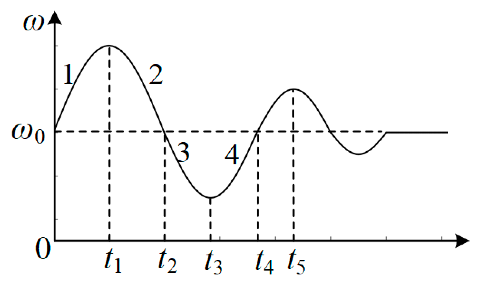
3. Analysis and Control of Electromechanical Oscillation

When the power system is disturbed, the torque balance of the rotor of the equivalent SG is broken, and the electromechanical oscillation will occur, which can be described by the power angle curve in Figure 5. Assume that the input power of the equivalent SG at the starting time is P0, suddenly jumps to P1 at a certain time, and reaches a new stable state after an oscillation process. According to the swing equation of the rotor of the equivalent SG, the power angle curve during the oscillation process can be divided into four stages, as shown in Figure 5.
After the system is disturbed and the electromechanical oscillation occurs, the grid frequency response curve of the equivalent SG is shown in Figure 6. When the damping of the power grid is not large enough, the first time period (corresponding to a a in Figure 5) is the accelerating process. When the equivalent SG runs to point a , the grid frequency reaches the maximum value. Due to the inertia effect of the power system, the equivalent SG will run beyond point a to point a , leading to the transient response with oscillation. In the above-mentioned process, if the power system accelerates too fast, that is, the ROCOF is too large [23], the frequency deviation of the power grid will be too large (corresponding to the period t1, t3, and t5 in Figure 6), and the oscillation amplitude will significantly increase. a in Figure 5 is closer to the critical stable point of the system, that is π/2, at which the stability margin of the power system decreases or even loses stability.
The drastic frequency change and violent power oscillation will trigger the action of relay protection of the power system, which will lead to the tripping-off of generators. Therefore, during the electromechanical oscillation process, it is necessary to guarantee that the ROCOF, the frequency deviation, and other key parameters are less than the protection thresholds of the power system, so as to ensure that the amplitudes of frequency oscillations and power oscillations are less than the limits the power system can withstand.
Therefore, the control of electromechanical oscillations must ensure that the power system meets the following frequency deviation constraint and the ROCOF constraint:
| ω ( t ) ω 0 | K ,
| d ω ( t ) d t | m ,
where, K is the frequency deviation threshold, and m is the ROCOF threshold of the power grid.
To reduce the maximum amplitude of power and frequency oscillations, a feasible solution is to make the ESS controller adjust its parameters online and in real time according to the operating state of the power system. Therefore, the ESS can flexibly change the inertia effect and the damping ability of the SG-based power system and provide the desired inertia and damping support for the power system to reduce the amplitudes of frequency and power oscillations, optimize the electromechanical oscillation process, and ensure that the relay protection is not triggered. The real-time operating state of the power system can be reflected by the real-time electromagnetic power, the frequency deviation, and ROCOF of the power system.
Under the premise of meeting the above basic requirements, if the ESS still has remaining capacity, its further operation goal is to compress the oscillation amplitude, reduce the oscillation cycles, shorten the oscillation time, and increase the stability margin of the system.

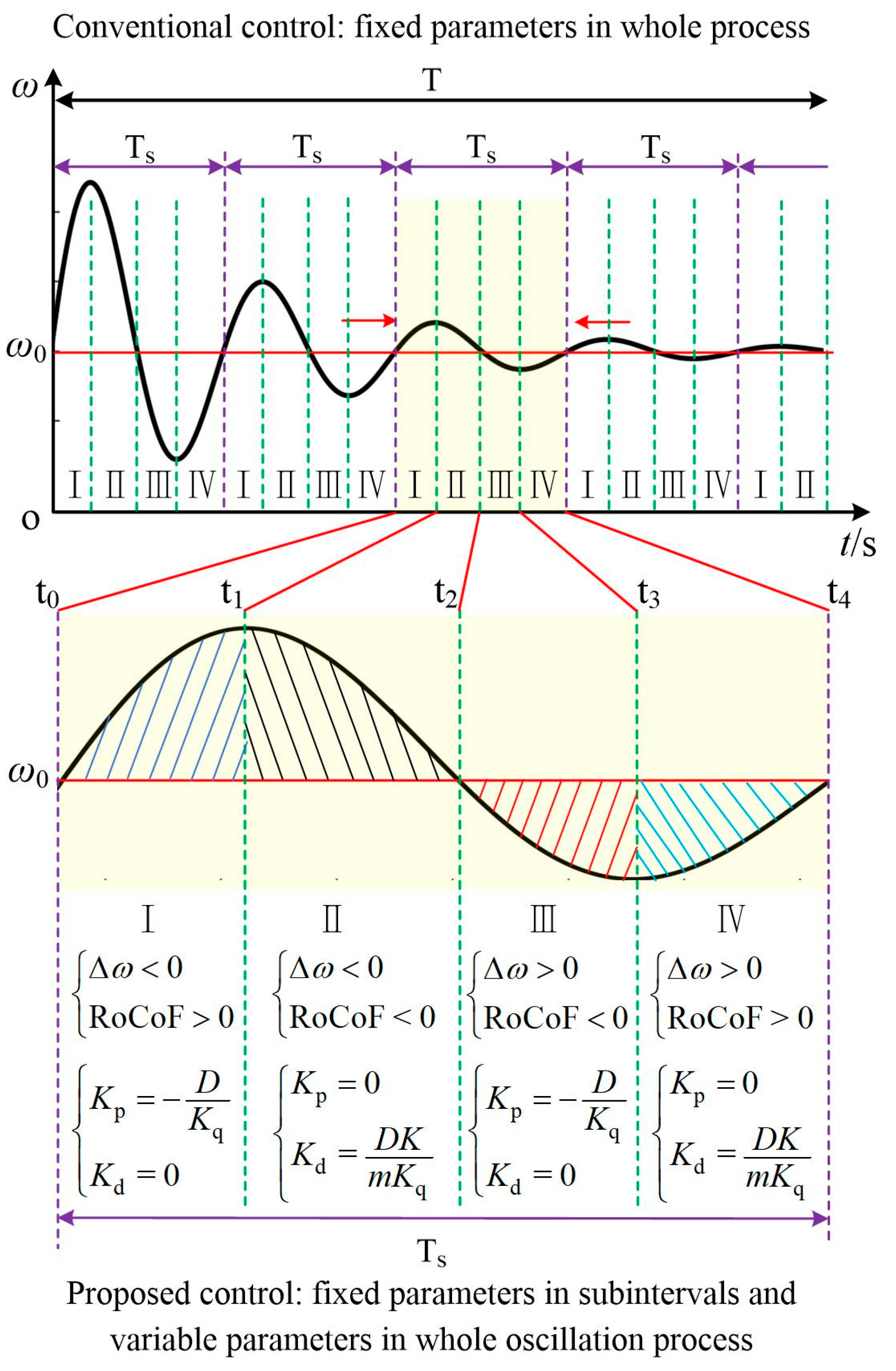
4. ESS Controller Parameter Design for Electromechanical Oscillation Suppression

Based on the above analysis, it can be known that when the power system runs stably, the feedback signal obtained by the ESS is 0, the ESS does not work, and the system inertia and damping parameters are the inherent coefficients of the equivalent SG-based power system. When the power grid is disturbed and the electromechanical oscillation occurs, the PID controller will act accordingly, and the controller parameters will be dynamically modified in real time according to the specific characteristics of the frequency oscillation. The inertia effect and damping ability of the power system are equivalently changed, so that the grid frequency is also changed according to the rules given by (12) and (13), so as to achieve better control performance.
When the power system is disturbed and begins to oscillate, the ESS will operate immediately. Based on (2) and (11), it can be known that the dynamic process of the equivalent SG system at this time satisfies the following equation:
T J d Δ ω d t = T S Δ δ T D Δ ω ,
Because the SG system itself has a strong synchronous operation capability, theoretically, the ESS does not have to provide additional synchronous torque to the power system [19]. That is to say, the ESS controller parameter Ki can be designed to be 0, which is the main reason why I controller-based control strategies are seldom used in the existing literature. In the simulation section of this paper, the parameter of the I controller is set as a value approximating to zero, therefore, the TS in (14) can be approximated as Kg. The research findings in [19] indicate that Kg is a parameter with a value close to 1. Considering that the change value Δδ of the power angle is usually small, it is approximated to 0 in most literatures. Based on this, the TSΔδ part in (14) can be ignored for the controller parameters’ design in this paper and (14) can be rewritten as:
T J d Δ ω d t = T D Δ ω ,
Considering the ROCOF constraint given by (13), in the limit condition, (15) can be rewritten as an algebraic equation under limit conditions. To remove the absolute value in (13), it can be divided into two cases; ROCOF greater than 0 and less than 0.

4.1. ROCOF > 0

When ROCOF is greater than 0, corresponding to Interval Ⅰ and Interval Ⅳ in Figure 7, (15) can be rewritten as
0 T J d Δ ω d t = T D Δ ω T J m ,
From the perspective of reducing the ESS capacity, the fundamental function of the ESS is to further strengthen or weaken the existing dynamic characteristics of the power system, instead of dominating the dynamics of the SG-dominated system. For instance, when the grid frequency accelerates, the ESS merely enhances or slightly weakens the acceleration, rather than trying to change the system from acceleration to deceleration. The former requires significantly less ESS capacity than the latter. Therefore, in this stage (ROCOF greater than 0), the ESS should conform to the existing acceleration trend of the power system, and provide some additional inertia effects to weaken the existing acceleration trend and ensure that the acceleration does not exceed the ROCOF threshold.
Therefore, in this period, the P controller parameter Kp should satisfy:
T J d Δ ω d t = T D Δ ω = ( D + K q K p ) Δ ω 0 ,
In this period, the D controller parameter Kd should satisfy:
( 2 H + K q K d ) m = T J m T J d Δ ω d t = T D Δ ω ,
The above constraints all involve Δω, and its value is related to the interval that the power system is located in. Therefore, the controller parameter design issue is discussed separately according to two cases: Δω < 0 and Δω > 0. Furthermore, considering that the constraint in (17) is only related to the P controller parameter Kp, Kp is designed first, and then the D controller parameter Kd is designed according to the constraint in (18).
Case A: Δω < 0 and ROCOF > 0 when the dynamic process is located in Interval Ⅰ (Figure 7).
In this period, when ROCOF is greater than 0, the grid frequency rises rapidly and gradually deviates from the steady-state point ω0. In order to shorten the oscillation process, prevent the grid frequency being far from ω0, and ensure that the grid frequency deviation is less than its threshold, it is necessary to increase the inertia effect in this period. The primary goal of the ESS is to suppress the ROCOF.
According to (17), when Δω < 0, the P controller parameter Kp should satisfy:
K p D K q ,
The above equation shows that the ESS can provide both positive damping torque and a certain amount of negative damping torque that should satisfy the constraint in (19). Obviously, the ESS also can provide zero damping effect. Therefore, in terms of saving ESS capacity, in this period, the ESS does not need to provide damping torque, and the equivalent damping coefficient of the power system can be designed as the inherent damping coefficient of the equivalent SG. Correspondingly, the controller parameter Kp is 0. Therefore, the constraint in (18) can be simplified as:
K d 1 K q ( 2 H + D m Δ ω ) ,
In order to satisfy the frequency deviation constraint in (12), there is:
Δ ω K ,
Considering (20), we have
1 K q ( 2 H + D m Δ ω ) 1 K q ( D m K 2 H ) ,
Considering the constraints in (22), it can be known that in this period, the constraint of the D controller parameter Kd given by (20) should satisfy:
K d 1 K q ( D m K 2 H ) ,
Therefore, in order to satisfy the frequency deviation constraint given by (12) and the ROCOF constraint in (13), in this period, the total inertia of the power system should satisfy:
T J = 2 H + K q K d D m K > 0 ,
To reduce the ESS capacity, the selected value of Kd can be the lower limit value in (24). Obviously, a certain amount of safety margin should be reserved. Therefore, for Interval I of Figure 7, the corresponding control parameters Kp and Kd can be set as follows:
{ K p = 0 K d = D K m K q ,
Case B: Δω > 0 and ROCOF is greater than 0 when the dynamic process is located in Interval IV, as shown in Figure 7.
In this period, when the ROCOF is greater than 0, the grid frequency rises rapidly and gradually approaches the steady-state point ω0. In order to accelerate the recovery process and allow the grid frequency to climb from the frequency nadir to ω0 as quickly as possible, there is no need to provide additional inertia effects in this period.
According to (17), when Δω > 0, the P controller parameter Kp should satisfy:
K p D K q ,
Therefore, in this period, the ESS can provide a certain amount of negative damping torque to the power system, so that the response curve of the grid frequency presents a divergent state in this period, prompting the transient frequency to return to the steady-state point ω0 as soon as possible, that is to rush from T3 to T4 at the fastest possible speed.
From another point of view, on one hand, excessive negative damping will lead to excessive output current and high capacity of the ESS; on the other hand, it will bring about drastic ROCOF, which will increase the inertia support provided by the ESS, and further intensify the capacity requirements for the ESS. In terms of cost and stability, the ESS should not provide excessive negative damping torque, and it only needs to meet the constraints in (12) and (13). Therefore, the P controller parameter Kp can be set according to the upper limit of (26), namely:
K p = D K q ,
Therefore, the equivalent damping coefficient of the power system can be close to 0, and the grid frequency can climb from the frequency nadir to ω0 at the fastest speed as long as the ROCOF is guaranteed not to exceed the threshold in the transient process, which is easy to achieve.
Substituting (27) into the constraint in (18) yields:
K d 2 H K q ,
Therefore, the parameter Kd of the D controller satisfies (28), ensuring that the ROCOF does not exceed the threshold in the transient process. Similarly, to reduce the ESS capacity, in this period, the ESS does not provide inertia support, that is, the D controller parameter Kd is 0.
Therefore, in Interval IV of Figure 7, the corresponding parameters Kp and Kd can be set as follows:
{ K p = D K q K d = 0 ,

4.2. ROCOF < 0

When ROCOF is less than 0, corresponding to Intervals II and III in Figure 7, (15) can be rewritten as:
T J m T J d Δ ω d t = T D Δ ω 0 ,
Therefore, in this stage, the P controller parameter Kp should satisfy:
T J d Δ ω d t = T D Δ ω = ( D + K q K p ) Δ ω 0 ,
Similarly, in this stage, the D controller parameter Kd should satisfy:
( 2 H + K q K d ) m = T J m T J d Δ ω d t = T D Δ ω ,
Similarly, the controller parameter design is also discussed according to two different cases, that are Δω < 0 and Δω > 0.
Case A: Δω < 0 and ROCOF is less than 0 when the dynamic process is located in Interval II (Figure 7).
During this interval, ROCOF is less than 0, the grid frequency drops rapidly and gradually approaches the steady-state point ω0. In order to accelerate the recovery process and make the grid frequency drop from the frequency peak to the steady state point as quickly as possible, there is no need to provide additional inertia effects in this interval.
According to (31), when Δω < 0, the P controller parameter Kp should still satisfy the constraint in (26). Therefore, the P controller parameter Kp in this interval can be designed according to (27) as in the case of Interval IV. Similarly, the D controller parameter Kd is designed to be 0, and the ESS does not provide inertia support so as to reduce the ESS capacity. Meanwhile, this design can also meet the constraints in (32), which can ensure that ROCOF does not exceed the threshold during the transient process.
Case B: Δω > 0 and ROCOF is less than 0 when the dynamic process is located in Interval III.
In this interval, ROCOF is less than 0 and the grid frequency drops rapidly and gradually deviates from the steady-state point. To shorten the oscillation process and to prevent the frequency deviation from exceeding the threshold, it is necessary to increase the inertia in this interval and the primary goal of the ESS is to suppress the ROCOF. Therefore, the design principle in this interval is the same as in Interval I, and the corresponding parameters Kp and Kd can still be set according to (25).
In summary, the ESS controller parameters Kp and Kd can be set according to the following rules:
K p = { 0 Δ ω × ROCOF > 0 D K q Δ ω × ROCOF < 0 ,
K d = { 0 Δ ω × ROCOF < 0 D K m K q Δ ω × ROCOF > 0 ,
The physical meaning of the above design rules is that when the grid frequency deviates from the steady-state point, the inertia support provided by the ESS will be greater when the value of the ROCOF constraint is smaller or the maximum frequency deviation is larger. When the grid frequency moves to the steady-state point, the ESS should promote this positive process, and provide a certain amount of negative damping torque to weaken the damping effect of the power system. It should try to create an undamped free-motion environment for the grid frequency dynamic to accelerate the frequency recovery process.

5. Simulation Verification

The Matlab/Simulink platform is used in this paper to verify the effectiveness of the proposed control strategy. The simulation model is shown in Figure 1, and the main parameters of the power system are shown in Table 1.

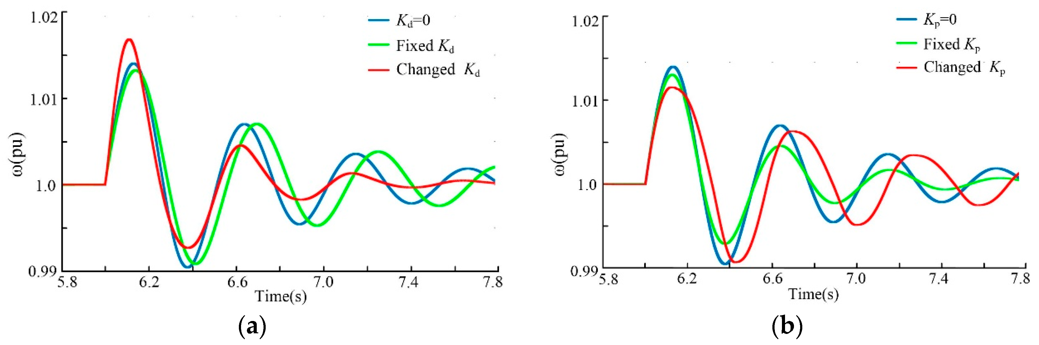
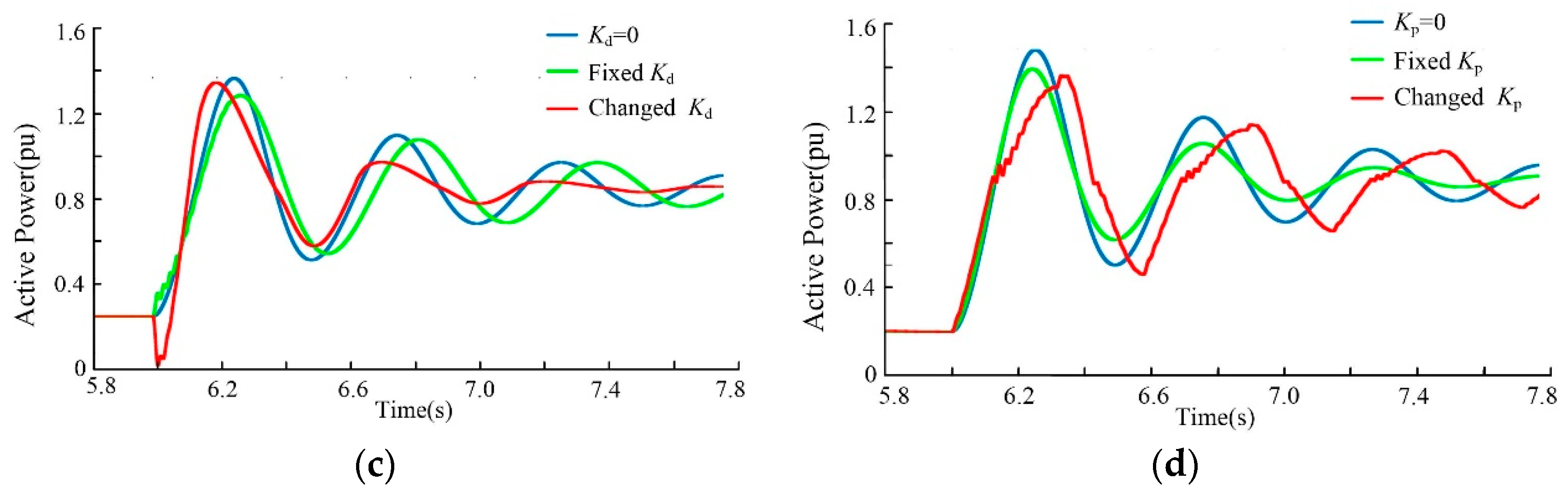
5.1. Effects of ESS Controller Parameters on System Dynamics

Figure 8 shows the simulation results of the grid frequency and the electromagnetic power of the equivalent SG when the parameters of the D and P controllers in the ESS change, respectively. The simulation results show that the P controller mainly affects the damping ability of the power system. The larger the P controller parameter, the stronger the damping ability of the power system, the faster the oscillation attenuation, the shorter the time required for the power grid to return to its stable state, and the more conducive it is to the stability of the power system. The D controller mainly affects the system inertia. The larger the D controller parameter, the stronger the system inertia, the smaller the maximum oscillation amplitude, and the longer the oscillation period. Increasing power grid stability is the general change trend, which is more conducive to power grid stability. It should be noted that when the D controller parameter is increased to a certain extent, the oscillation time will be longer, and it is possible to trigger the power system separation device. Furthermore, an excessive D controller parameter leads to the system poles close to the right half plane of the eigenvalue complex plane, which is not conducive to the small signal stability of the power system. The simulation results in Figure 8a,c confirm this feature. When the D controller parameter increases to a certain value, the electromagnetic power will oscillate at a subsynchronous frequency.
The change of ESS controller parameters can indirectly change the inertia effect and damping ability of the power system, so that the electromechanical oscillation can be effectively suppressed. However, since the controller parameters remain constant throughout the whole oscillation process, the inertia and damping provided by the ESS cannot be flexibly adjusted according to the operation status of the power system, the performance of oscillation suppression is always limited, and the dynamic performance of the power system cannot be further improved. As shown in Figure 8a and Figure 8c, with the increase of Kd, the system inertia increases and the oscillation amplitude decreases significantly, while the time for the system to return to its steady-state point becomes much longer. In the process of the system moving towards the steady-state point, this process is expected to occur at the fastest possible speed, however, due to the fixed inertia parameter, the recovery process to the steady-state point cannot be effectively accelerated. As shown in Figure 8b,d, as the Kp increases, the damping ability of the power system increases, the oscillation peak decreases, and the attenuation speed increases, while the oscillation period is hardly affected. Therefore, fixed inertia and damping cannot achieve the desired oscillation suppression. It is necessary to flexibly adjust the inertia and damping effects according to the specific stage of the oscillation process.

5.2. Independent Action of Damping Control and Inertia Control

To optimize the process of oscillation suppression, firstly, the inertia and damping are no longer fixed during the whole oscillation process. In this section, the D and P controller parameters are separately designed according to the proposed controller parameter design method, so that the inertia or the damping can be flexibly adjusted online according to the specific stage of the grid frequency response. Figure 9 shows the simulation results of the grid frequency and the electromagnetic power when the D and P controller parameters act independently.
Compared with the case of fixed controller parameters, the parameter online optimization can improve the performance of oscillation suppression, but it still cannot achieve a fast and stable response. As shown in Figure 9a,c, when the inertia is adjusted, the recovery time of the system is shortened, but the maximum oscillation amplitude is slightly increased. In Figure 9b,d, when the damping effect is adjustable, the recovery rate of the grid frequency changes at different stages. However, the overall recovery speed of the system slows down, and the suppression performance has not been significantly improved. Therefore, it is necessary to combine the inertia control with the damping control, and simultaneously adjust the inertia and damping effects according to the specific stage of the oscillation to further accelerate the recovery process of the power system.

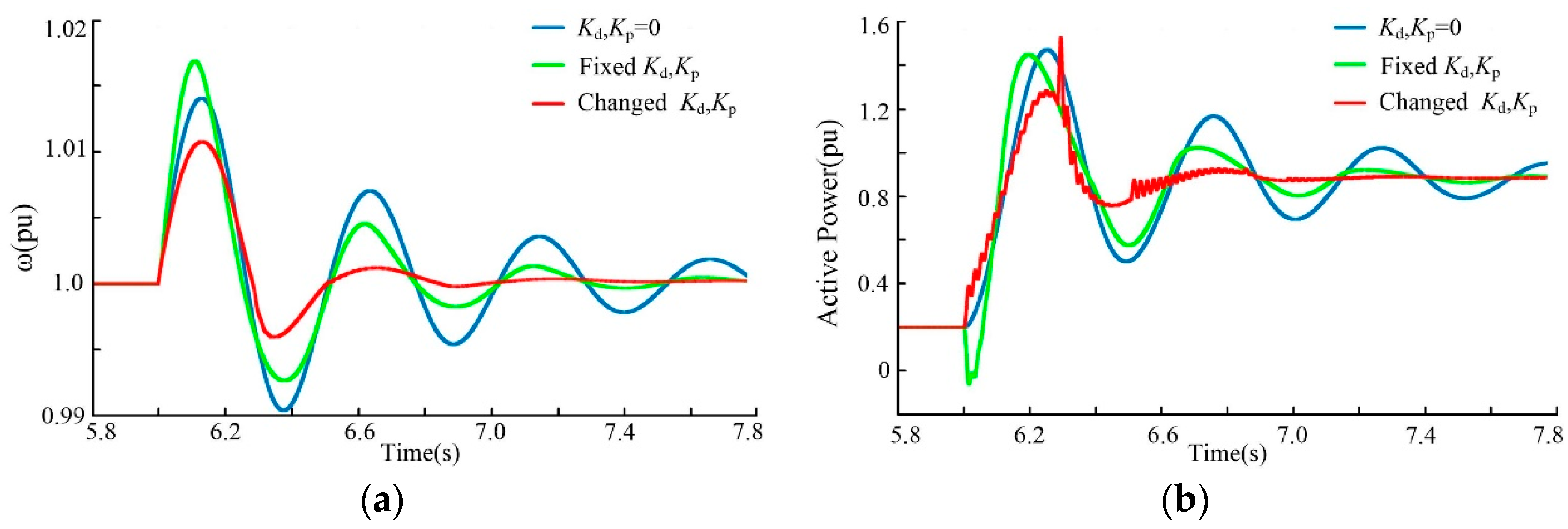
5.3. Coordinated Action of Damping Control and Inertia Control

Figure 10 shows the simulation results of coordinated action of damping control and inertia control. The simulation results show that, compared with independent damping control or inertia control, the oscillation suppression achieves better performance when the D and P controller parameters are simultaneously adjusted online according to the specific stage of the grid frequency response. The coordinated action of damping control and inertia control can simultaneously reduce the oscillation amplitude and the oscillation time significantly. The simulation results verify the effectiveness of the proposed controller parameter design method for ESSs.

6. Conclusions

By feeding back the rotor speed and/or the grid frequency, the ESS can equivalently change the inertia and damping of the power system, thereby suppressing electromechanical oscillation. When conventional control with fixed controller parameters is used throughout the whole oscillation process, the inertia and damping provided by the ESS are also fixed, and cannot be flexibly adjusted according to the operation status of the power system, so the performance of oscillation suppression is limited. The proposed control system with variable controller parameters can help the ESS to achieve the desired performance of oscillation suppression, while keeping smaller frequency deviation and ROCOF below their thresholds. Through online adjustment of the ESS controller parameters, which is achieved by the proposed controller parameter design method, the system’s equivalent inertia and damping can be adjusted flexibly and simultaneously, which can improve the dynamic performance of electromechanical oscillation suppression and the stability margin of the power system. The simulation results verify the effectiveness of the proposed control strategy and ESS parameter design method for electromechanical oscillation suppression within power systems.

Author Contributions

All the authors conceived and designed the study. B.Y., G.L. and A.H. performed the theoretical analysis and wrote the manuscript with the guidance from Professor W.T.; D.Z. and Y.W. conceived and designed the simulation experiments.

Acknowledgments

The work was supported by the Technology Projects of China State Grid Corporation titled “Research and Application of Active Support Technology for Large New Energy Power Station Based on Energy Storage” (Grant No. NY71-16-045) and “The Study on Modularized and Cascaded Converter System for Energy Storage Application” (Grant No. NY83-18-007).

Conflicts of Interest

The authors declare no conflict of interest.

References

  1. Shu, D.; Xie, X.; Rao, H.; Gao, X.; Jiang, Q.; Huang, Y. Sub-and super-synchronous interactions between STATCOMs and weak AC/DC transmissions with series compensations. IEEE Trans. Power Electron. 2018, 33, 7424–7437. [Google Scholar] [CrossRef]
  2. Wang, H.; Wu, M.; Sun, J. Analysis of low-frequency oscillation in electric railways based on small-signal modeling of vehicle-grid system in dq frame. IEEE Trans. Power Electron. 2015, 30, 5318–5330. [Google Scholar] [CrossRef]
  3. Zhang, J.; Chung, C.Y.; Han, Y. A novel modal decomposition control and its application to PSS design for damping interarea oscillations in power systems. IEEE Trans. Power Syst. 2012, 27, 2015–2025. [Google Scholar] [CrossRef]
  4. Channegowda, P.; John, V. Filter optimization for grid interactive voltage source inverters. IEEE Trans. Ind. Electron. 2010, 57, 4106–4114. [Google Scholar] [CrossRef]
  5. Alawasa, K.M.; Mohamed, Y.A.R.I.; Xu, W. Active mitigation of sub-synchronous interactions between PWM voltage-source converters and power networks. IEEE Trans. Power Electron. 2014, 29, 121–134. [Google Scholar] [CrossRef]
  6. Oudalov, A.; Chartouni, D.; Ohler, C. Optimizing a battery energy storage system for primary frequency control. IEEE Trans. Power Syst. 2007, 22, 1259–1266. [Google Scholar] [CrossRef]
  7. Leon, A.E.; Mauricio, J.M.; Solsona, J.A. Sub-synchronous resonance mitigation using variable speed wind energy conversion systems. IET Gener. Transm. Distrib. 2013, 7, 511–525. [Google Scholar] [CrossRef]
  8. Wang, L.; Xie, X.; Jiang, Q.; Liu, H.; Li, Y.; Liu, H. Investigation of SSR in practical DFIG-based wind farms connected to a series-compensated power system. IEEE Trans. Power Syst. 2015, 30, 2772–2779. [Google Scholar] [CrossRef]
  9. Yang, L.; Yang, G.Y.; Xu, Z.; Dong, Z.Y.; Wong, K.P.; Ma, X. Optimal controller design of a doubly-fed induction generator wind turbine system for small signal stability enhancement. IET Gener. Transm. Distrib. 2010, 4, 579–597. [Google Scholar] [CrossRef]
  10. Hassan, L.H.; Moghavvemi, M.; Almurib, H.A.; Muttaqi, K.M. A coordinated design of PSSs and UPFC based stabilizer using genetic algorithm. IEEE Trans. Ind. Appl. 2014, 50, 2957–2966. [Google Scholar] [CrossRef]
  11. Khaled, M.A.; Yasser, A.I.M. A Simple approach to damp SSR in series-compensated systems via reshaping the output admittance of a nearby VSC-based system. IEEE Trans. Ind. Electron. 2015, 62, 2673–2682. [Google Scholar]
  12. Mohamed, S.E.; Birgitte, B.J.; Mansour, H.A. Novel STATCOM controller for mitigating SSR and damping power system oscillations in a series compensated wind park. IEEE Trans. Power Electron. 2010, 25, 429–441. [Google Scholar]
  13. Mithulananthan, N.; Canizares, C.A.; Reeve, J.; Rogers, G.J. Comparison of PSS, SVC, and STATCOM controllers for damping power system oscillations. IEEE Trans. Power Syst. 2007, 18, 786–792. [Google Scholar] [CrossRef]
  14. Xiong, L.; Liu, X.; Wang, F.; Zhuo, F. Static synchronous generator model for investigating dynamic behaviors and stability issues of grid-tied Inverter. In Proceedings of the 2016 IEEE Applied Power Electronics Conference and Exposition (APEC), Long Beach, CA, USA, 20–24 March 2016. [Google Scholar]
  15. Xiong, L.; Zhuo, F.; Wang, F.; Liu, X.; Chen, Y.; Zhu, M.; Yi, H. Static synchronous generator model: A new perspective to investigate dynamic characteristics and stability issues of grid-tied grid-tied PWM inverter. IEEE Trans. Power Electron. 2016, 31, 6264–6280. [Google Scholar] [CrossRef]
  16. Lopes, L.A. Self-tuning virtual synchronous machine: A control strategy for energy storage systems to support dynamic frequency control. IEEE Trans. Energy Convers. 2014, 29, 833–840. [Google Scholar]
  17. Alipoor, J.; Miura, Y.; Ise, T. Power system stabilization using virtual synchronous generator with alternating moment of inertia. IEEE J. Emerg. Sel. Top. Power Electron. 2015, 3, 451–458. [Google Scholar] [CrossRef]
  18. Alipoor, J.; Miura, Y.; Ise, T. Distributed generation grid integration using virtual synchronous generator with adoptive virtual inertia. In Proceedings of the 2013 IEEE Energy Conversion Congress and Exposition (ECCE), Denver, CO, USA, 15–19 September 2013. [Google Scholar]
  19. Xiong, L.; Wang, D. Research on suppression mechanism of STATCOM on power oscillations. In Proceedings of the 2017 IEEE 3rd International Future Energy Electronics Conference and ECCE Asia (IFEEC 2017-ECCE Asia), Kaohsiung, Taiwan, 3–7 June 2017; pp. 806–811. [Google Scholar]
  20. Xiong, L.; Xu, Z.; Xiu, L. Energy Storage System Control for Electromechanical Oscillation Mitigation and Its Impact on Inertia and Damping of Power System. In Proceedings of the 2018 IEEE 4th Southern Power Electronics Conference (SPEC), Singapore, 10–13 December 2018; pp. 1–5. [Google Scholar]
  21. Xiong, L.; Zhuo, F.; Liu, X.; Zhu, M.; Chen, Y.; Wang, F. Research on fast open-loop phase locking scheme for three-phase unbalanced grid. In Proceedings of the 2015 IEEE Applied Power Electronics Conference and Exposition (APEC), Charlotte, NC, USA, 15–19 March 2015; pp. 1672–1676. [Google Scholar]
  22. Xiong, L.; Zhuo, F.; Wang, F.; Liu, X.; Zhu, M.; Yi, H. A Novel Fast Open-loop Phase Locking Scheme Based on Synchronous Reference Frame for Three-phase Non-ideal Power Grids. J. Power Electron. 2016, 16, 1513–1525. [Google Scholar] [CrossRef]
  23. Fang, J.; Li, H.; Tang, Y.; Blaabjerg, F. On the inertia of future more-electronics power systems. IEEE J. Emerg. Sel. Top. Power Electron. 2018, 1–19. [Google Scholar] [CrossRef]
Figure 1. Equivalent model of synchronous generator (SG)-dominated power system with an energy storage system (ESS).
Applsci 09 01329 g001
Figure 2. Control diagram of an ESS with the feedback signal of the rotor speed. (a) Conventional control with fixed controller parameters; (b) Proposed control with variable controller parameters.
Applsci 09 01329 g002
Figure 3. Equivalent model on the electromechanical time scale.
Applsci 09 01329 g003
Figure 4. Voltage vector diagram of an equivalent system.
Applsci 09 01329 g004
Figure 5. Power angle curve of the equivalent SG.
Applsci 09 01329 g005
Figure 6. Grid frequency response curve.
Applsci 09 01329 g006
Figure 7. Illustration of proposed control scheme and its parameter design method.
Applsci 09 01329 g007
Figure 8. Effects of ESS controller parameters on system dynamics. (a) Frequency with D controller; (b) frequency with P controller; (c) SG power with D controller; (d) SG power with P controller.
Applsci 09 01329 g008
Figure 9. Independent action of damping control and inertia control. (a) frequency with D controller; (b) frequency with P controller; (c) SG power with D controller; (d) SG power with P controller.
Applsci 09 01329 g009aApplsci 09 01329 g009b
Figure 10. Coordinated action of damping control and inertia control. (a) Grid frequency; (b) electromagnetic power of the equivalent SG.
Applsci 09 01329 g010
Table 1. System parameters.
ParametersValuesParametersValues
Utility voltage U10.5 kV/50 HzESS DC-side voltage Vdc800 V
Line impedance Z0.02 + j0.5 ΩESS location k1
Frequency deviation threshold K0.5 HzROCOF threshold m0.1 Hz/ms

