Article

Compensation of Frequency Drift in Frequency-Sweep Polarization-Modulation Ranging System

1
School of Instrument Science and Optoelectronic Engineering, Hefei University of Technology, Hefei 230009, China
2
Institute of Microelectronics of The Chinese Academy of Sciences, Beijing 100029, China
3
School of Optics and Photonics, Beijing University of Technology, Beijing, 100081, China
4
University of Chinese Academy of Sciences, Beijing 100049, China
*
Author to whom correspondence should be addressed.
Appl. Sci. 2019, 9(6), 1243; https://doi.org/10.3390/app9061243
Submission received: 29 January 2019 / Revised: 5 March 2019 / Accepted: 20 March 2019 / Published: 25 March 2019
(This article belongs to the Special Issue Precision Dimensional Measurements)

Abstract

:

Featured Application

Absolute distance measurement.

Abstract

In frequency-sweep polarization-modulation ranging, distance is determined by the frequency of modulated waves and the corresponding wavelength multiple when emitted and returned waves are in phase. However, measurement of the frequency and the wavelength multiple is affected by thermally induced phase delay of the polarized wave. In this article we systematically discuss the principle of the ranging method and analyze the influences of thermally induced phase delay. New approaches to measurement are proposed to eliminate the impact on frequency and the wavelength multiple. Theoretical analysis and experimental results proved the efficiency and applicability of the methods.

1. Introduction

Absolute distance measurement (ADM) technologies are of significant application in scientific and engineering fields such as large equipment manufacturing, spacecraft fabrication, and general-purpose coordinate measurements [1,2,3]. Various methods of ADM have been developed over the past decades, such as phase shift-based ranging [4,5,6], frequency scanning interferometry-based ranging [7,8,9,10], multi-wavelength interference-based ranging [11,12,13,14], and femtosecond optical comb-based ranging [10,15,16,17]. In recent years, the latter three technologies have achieved great accuracy in laboratory, but the systems are complex and their performance needs to be enhanced in an industrial setting. The phase shift ranging method is a common technology in industry, in which the phase differences between continuous emitted and reference waves are compared. However, in phase shift ranging systems, the performance of phase discrimination is influenced by parasitic parameters in the circuit, and as a result ranging precision is limited.
The frequency-sweep polarization-modulation (FSPM) method is another phase ranging method in which modulation frequency is scanned and searched when emitted and returned waves are in phase, thus avoiding the environmental disturbance as well as shortage of phase discrimination [18,19,20]. It was proposed by Kern & Co. Ltd. and first applied in the commercial distance meter ME5000 [21,22,23]. Due to its simple structure and high resolution, the FSPM ranging technique has the potential for small size and high performance. However, in the FSPM ranging system, the frequency is vulnerable to phase delay variation due to the sensitivity of crystals (e.g., LiNbO3) in the electro-optic modulator (EOM) to temperature disturbance. The heat dissipation of electronic components and laser irradiation will accelerate the temperature variation [24], thus leading to distance measurement errors.
In order to investigate this problem, a theoretical model was developed for the FSPM ranging systems. Based on the model, a correction approach for diminishing the thermally-induced errors in the system was proposed. A reciprocating sweeping method and multi-frequency interval method were respectively proposed to improve the measurement accuracy of frequency and the corresponding wavelength multiple. The validity of the method was proved by theoretical analysis and experiments. The article is organized as follows: In Section 2, the principle of the FSPM-based system is introduced, measurement errors due to phase delay are discussed, and the compensation methods are proposed. In Section 3, experiments are conducted to prove the effectiveness of the methods. Finally, a brief conclusion is given in Section 4.

2. Principle and Method

2.1. The Principle and Model

The frequency-sweep polarization-modulation ranging system consists of a continuous wave laser, an isolator, a polarizing beam splitter (PBS), an EOM, a quarter wave plate (QWP), a beam expander (EXP) and the target, as shown in Figure 1.
To illustrate the working principle of the FSPM ranging method, a Cartesian coordinate system is established. The z-axis represents the direction of wave propagation, while the x-axis is the polarization direction of linearly polarized light generated by the laser. In the system, continuous polarized light emitted by the laser travels through an isolator and a PBS tipped 45 degrees from the x-axis, so equal amplitude of polarization components in the x-axis and y-axis is achieved when light travels into the EOM. The EOM generates phase retardation between the two components in a sinusoidal manner with linearly changed frequency. The QWP has a fast axis oriented at 45 degrees to the x-axis, so the light travels to the target and returns by the same path, to then be demodulated by the EOM. The phase difference between the polarization components when light transmits through the EOM successively can be respectively described as:
φ 1 =   k sin ( ω t ) , φ 2   =   k sin ( ω t + φ ) + δ T ,
where ω is the modulation frequency, k represents the modulation depth, δ T represents the additional phase delay between the polarization components, φ is the phase shift of the modulation signal during the round-trip time, and φ = 4πf(t)nl/c, where f(t) is the modulation frequency, c represents the speed of light in vacuum, n is the refractive index of the air, and l is the distance to be measured. Note that in the equation, 0 < k 1 for linear modulation and δ T is small, typically less than π/2. With the amplitude of x and y components normalized, the intensity of light received by the detector can be written as:
I   =   1     cos ( φ 1     φ 2 )   =   1     cos ( 2 k cos 2 ω t   +   φ 2 sin φ 2 ) · cos δ T   +   sin ( 2 k cos 2 ω t   +   φ 2 sin φ 2 )   ·   cos δ T .
After simplification and filtering the high-frequency components, the equation can be rewritten as:
I   =   1 ( 1 k 2 2 + k 2 2 cos φ ) · cos δ T .
Obviously, if cos δ T is constant, there exists a cosine relationship between intensity and modulation frequency. Minimums of the equations By obtaining the corresponding frequencies fx, fx+1 (k∈N) at adjacent minima, the distance can be determined by:
l   =   N · c 2 n f x ,   in   which   N   =   [   f x f x + 1 f x   ] ,
where, N is the wavelength multiple, [ ] is the rounding operation, fx/(fx+1fx) is the initial value of the wavelength multiple, which comprises an integer and a fraction part, so the rounding operation is necessary. For convenience in the manuscript, The frequencies fx and fx+1 will be defined as “in phase” frequency. Value of difference of adjacent in-phase frequencies i.e., fx+1fx will be defined as frequency interval fb, which is ideally a constant when distance is invariant.

2.2. Influence of Thermally Induced Phase Delay and Traditional Correction Method

In a transverse modulator configuration, the effects of temperature variation on modulation characteristics are mainly as follows: first, due to the thermo-optic effect of the crystal, the refractive index of the crystal changes with temperature. More concretely, the change in the refractive index along the direction of light transmission causes the optical path variation of light, and the change in refractive index perpendicular to the direction of light transmission results in an additional phase delay of the polarization [25]. Second, due to the elasto-optical effect of the crystal, the stress caused by the thermal expansion of the crystal also changes the refractive index and the longitudinal length of the crystal. As a result, the thermally induced phase delay can be expressed as follows:
δ T = 2 π λ Δ n t l + 2 π λ n t Δ l ,
where λ represents wavelength of light, nt is the initial value of natural birefringence in the direction perpendicular to light transmission, and   Δ n t is the thermally induced birefringence variation. l represents the initial value of the length of the crystal, and Δ l is the thermally induced variation of the crystal length.
Several techniques have been applied to compensate for the thermally induced phase delay in the applications of EOM. An example of this is connecting a compensate crystal that has the same size and performance with the modulate crystal, with the optical axes of the crystals perpendicular to each other so that the phase delay in the two identical crystals are complementary [26]. Another way is to make the two crystals in series, with one half-wave plate placed in the middle of them to make the polarization plane of the polarized light rotate by λ/2 [24]. In these methods, crystals with exactly the same parameters and their perfect assembly are the key to compensation, but that is difficult to achieve. In the FSPM ranging system, a quarter-wave plate is placed between the crystal and the target so that when light passes through the quarter-wave plate during emitting and returning, the plane of polarization can be rotated by λ/2 to achieve the complementation [27,28]. In this structure, the adjustment is simpler and the compensation is better. However, in the FSPM ranging system, a mismatch of polarizing devices and reflection of polarized light are inevitable and lead to the additional rotation of the polarization plane of light. Even a very small mismatch of polarization devices or any reflection in the system will result in the rotation of the polarization plane, and produce residual thermally induced phase delay.
In our experiment, the residual thermally induced phase delay was tested first. Since thermally induced phase delay varies slowly, it can be measured through a polarization analysis system (Thorlabs, PAX5710). At the same time, the temperature in the modulator chamber was tested with a high-precision temperature controller (Wavelength, Tc_lab), with results shown in Figure 2. As is shown, with the increase of temperature, the phase delay slowly increased, accompanied by periodic oscillation, and when temperature growth slowed down, the oscillation speed also decreased.

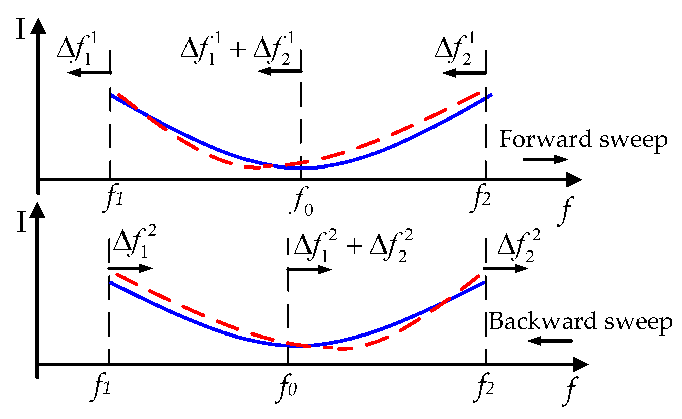
2.3. Reciprocating Sweeping-Based Measurement of “in Phase” Frequency

The change of additional phase delay accelerates or decelerates the polarization variation when the wave is modulated across the “in phase” frequency, thus destroying the symmetry of the intensity curve, leading to the shift of minima. The shift can be manifested in variation of the curve slope. Through the derivation of Equation (3), the slope of the intensity curve at the ideal minimum φ 0 can be written as:
I ( φ 0 ) = lim Δ φ 0 I ( φ 0 + Δ φ ) I ( φ 0 Δ φ ) 2 Δ φ = lim Δ φ 0 ( 1 k 2 2 + k 2 2 cos Δ φ ) ( sin δ 0 sin Δ δ ) Δ φ ,
where δ 0 is the thermally induced phase delay when   φ   =   φ 0 , Δ φ is the increment on point of φ 0 , Δδ is the increment on point of δ0. According to the above equation, I ( φ 0 ) is a result of interaction between modulation depth, frequency scanning, and phase delay variation. Large modulation depths and frequency sweep speed are beneficial for eliminating the effect of thermally induced phase delay. However, modulation depth and sweep speed are often limited owing to equipment limitations, and a larger modulation depth requires a larger microwave voltage, thus aggravating the heating problem of the modulation circuit. Interestingly, we found that Equation (6) is an odd function about φ, so the orientation of the frequency shift can be controlled through frequency sweep directions. When modulation frequency is swept forward (i.e., from the lower frequency to the higher frequency), Δφ(t) > 0, otherwise, Δφ(t) < 0. Therefore, during the forward and backward sweep, the minimum drifts in opposite directions. Through averaging of such reciprocating sweeping, the drift errors can be diminished and frequency measurement stability can be improved. The method is further analyzed below.
Suppose the ideal frequency under test is f0. f1 and f2 are frequencies very close to f0 and satisfy the equations f1 = f0δf and f2 = f0 + δf. If the system is not affected by thermally induced phase delay, obviously we get the equation I(f1) = I(f2), then the exact value of f0 can be worked out through: f0 = (f1 + f2)/2. However, due to thermally induced phase delay, during the forward sweeping, f1 and f2 respectively moves Δ f 1 1 and Δ f 2 1 towards lower frequency, then in the backward sweeping, f1 and f2 respectively moves Δ f 1 2 and Δ f 2 2 towards the opposite side, as shown in Figure 3.
Taking random measurement errors υ into account, the extremum of the measurements are respectively expressed as:
f 0 1 = ( f 1 Δ f 1 1 ± | υ 1 1 | ) + ( f 2 Δ f 2 1 ± | υ 2 1 | ) 2 , f 0 2 = ( f 1 + Δ f 1 2 ± | υ 1 2 | ) + ( f 2 + Δ f 2 2 ± | υ 2 2 | ) 2 .
Through n times of such sweeps, the frequency can be obtained by:
f 0 = 2 n ( f 1 + f 2 ) + i = 1 n ( Δ f 1 2 n     Δ f 1 2 n 1 ) + i = 1 n ( Δ f 2 2 n     Δ f 2 2 n 1 ) ± i = 1 2 n | υ 1 n | ± i = 1 2 n | υ 2 n | 4 n .
During the time of reciprocating sweeping, variation of δ is small so items of i = 1 n ( Δ f 1 2 n Δ f 1 2 n 1 ) and i = 1 n ( Δ f 2 2 n Δ f 2 2 n 1 )   can be diminished to some extent, and the random measurement error of frequency can be compensated by averaging.

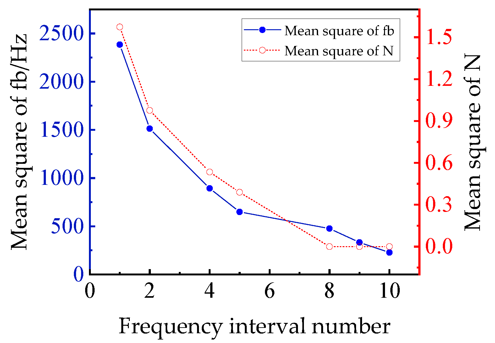
2.4. Multi-Frequency Interval-Based Measurement of Frequency Interval

Although frequency error can be partially eliminated through the reciprocating sweeping method, measurement of N requires a higher accuracy of frequency. The measurement error of N can be expressed as:
Δ N = [ Δ f x   f x Δ f b   · f x   f b 2 ] = [ Δ f b   · f x   f b 2 ] .
The above equation indicates that the absolute error of N is determined by the relative error of fb. However, in the FSPM method, the impact of relative error of fb is often 2N times larger than the relative error of fx, which means the accuracy of fx may not meet the accuracy requirement of fb. If fx is around 2.5 GHz, l is about 100 m, a frequency measurement error of 2500 Hz only contributes a ranging error of 100 μm, but the resulting relative error of fb contributes a ranging error of 0.36 m. To ensure the accuracy of N, Δfb should be less than 90 Hz, which cannot be satisfied by the reciprocating sweeping method.
In order to reduce the measurement error of fb, we used the characteristic of equal spacing of the “in phase” frequencies in our multi-frequency interval-based approach. For example, fb can be expressed as follows:
f b = ( f x + u     f x )   u   ,
where fx is an arbitrary “in phase” frequency in sweeping band, fx+u is the uth “in phase” frequency on its upper side. Therefore, N can be rewritten as:
N = [ f x   f b ] = [ u · f x f x + u f x ] .
Hence, taking the frequency drift and random measurement error into account, the multi-frequency interval can be expressed as:
f x + u f x =   u · f b ± Δ f u ± ( | υ x + u | + | υ x | ) ,
where Δ f u represents the frequency drift. The measurement error of the wavelength multiple can be expressed as:
Δ N = [ Δ f x f b f x · Δ ( f x + u f x ) u · f b 2   ] [ f x · Δ ( f x + u f x ) u · f b 2   ] = [ f x Δ ( ± Δ f u ± ( | υ x + u | + | υ x | ) ) u · f b 2   ] .
Therefore, errors caused by frequency drift and random measurement error are u times narrower than the general method.
In the above method, u can be determined by the following equation:
u   [   f x + u     f x f x + 1     f x   ] .
According to the expression of Δ u :
Δ u = [ Δ ( f x + u f x ) f b Δ ( f x + 1 f x ) u · f b   ] = [ ± Δ f u ± ( | υ x + u | + | υ x | ) f b ± Δ f 1 ± ( | υ x + 1 | + | υ x | ) u · f b ] .
The items are small quantities, that is, ± Δ f u ± ( | υ x + u | + | υ x | ) / f b 1 , ± Δ f 1 ± ( | υ x + 1 | + | υ x | ) / ( u f b ) 1 , so u can be accurately acquired.

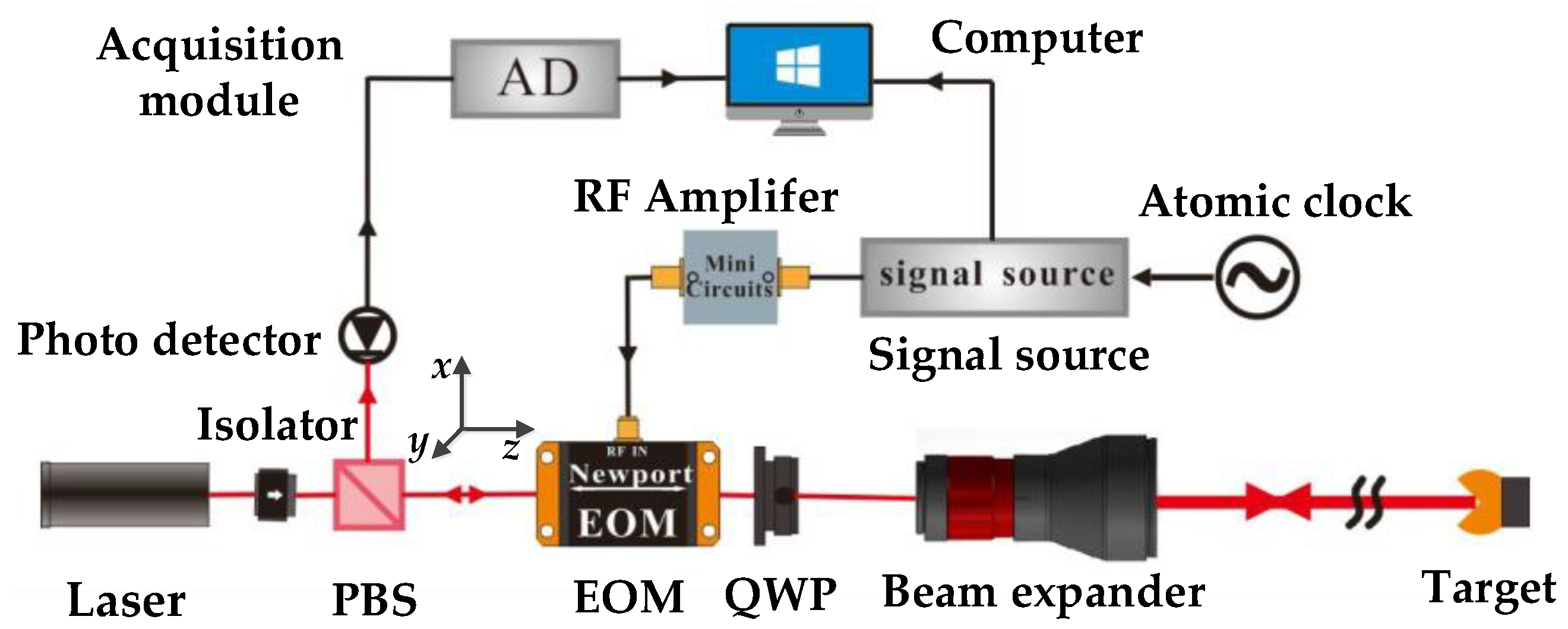
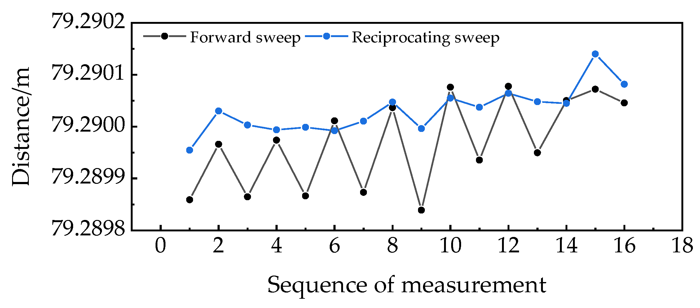
3. Experimental Results and Discussion

In order to verify the effectiveness of above methods, the experimental system shown in Figure 1 was established and several experiments were conducted. In the system, a He-Ne laser (Newport R-32734) served as the light source, a high-frequency phase modulator (Newport, 4431, Vπ is 40 V) served as the modulator, a signal generator (Keysight, N5171B) provided the modulation signal, the preset sweeping range was set from 2.500 to 2.520 GHz, with a sweep step size of 1 kHz. The residence time at each frequency was 20 ms. An avalanche detector (Thorlabs, APD410A) was used for the photoelectric conversion. A PXI oscilloscope (NI, 5171R) served as the acquisition and processing module. The target was approximately 80 m away from the crystal.
To evaluate the method of reciprocating sweep in compensation of thermally induced phase delay, an “in phase” frequency was obtained by different methods and results are shown in Figure 4. In the figure, black and red dots respectively denote the results obtained through forward and backward sweep, and blue dots denote the average of measurement results obtained by the reciprocating sweep. Results obtained through forward and backward sweeps drifted in opposite directions, and the forward sweeps had a larger statistical average than that of the backward sweeps. Through reciprocating sweeps, the results had a repeatability of 1727 Hz, which was much smaller than that of forward sweep (3130 Hz) and backward sweep (2503 Hz).
To validate our measurement method of N, N was tested with multi-frequency intervals. The “in phase” frequency fx near the lower edge of band was first obtained in the reciprocating sweep method, then, the uth “in phase” frequency on its upper side was obtained, and fb and N were respectively determined according to Equations (10) and (11). u was set to change from 1 to 10 in seven groups of tests, each group of tests contained 10 independent measurements; the statistical results are shown in Figure 5. In the single-frequency interval method, the mean squares of fb and N were 2384 Hz and 1.5, respectively. As u increased from 1 to 8, the mean square of fb was reduced to 332 Hz, and the mean square of N was reduced to 0. Further increase of u would result in further reduction of the standard deviation of fb, but in our experiment, the frequency interval number of 8 was sufficient for an accurate measurement of N.
With the accurate measurement of N, distance could be determined through the “in phase” frequency and the corresponding N; results are shown in Figure 6. The statistical average of the forward sweeps was 6 µm larger than the backward sweeps. The statistical uncertainties of the forward sweeps and reciprocating sweeps were 87.1 µm and 44.1 µm, respectively.
Finally, an uncertainty test was conducted using a dual-frequency laser interferometer. The target retroreflector was moved from 79.29 to 80.29 m by ten steps at an increment of 100 mm. A commercial heterodyne interferometer (5519, Keysight) was used to measure the displacement of the target. By the application of linear fitting, the residual error between the reference displacement and the measured distance could be obtained as shown in Figure 7. The residual error of the forward sweep was from −85.9 to 113 μm. With the reciprocating sweep method, the max residual error was 54.4 μm. The relative error was attributed to the random measurement error of frequency, the temperature dependence of crystal properties, the air-path distance variation, and the instability of frequency reference. The random measurement error of frequency could be further reduced by reducing the sweep step size and increasing the signal-to-noise ratio of the system. The temperature dependence of crystal property included the refractive index and the length change on the optical path, and air-path distance variation was mainly caused by the variation of the air refractive index.

4. Conclusions

We systematically discussed the principle of the FSPM based ranging method and the impact of thermally induced phase delay on “in phase” frequency and wavelength multiple. To eliminate the frequency drift caused by the phase delay, a measurement method based on a reciprocating sweep was proposed. To obtain an accurate wavelength multiple, a multi-frequency interval approach was proposed according to the equal interval distribution of “in phase” frequencies. The results of our experiment proved the efficiency and applicability of the methods. The maximum deviation of the measured results between the FSPM-based system and the interferometer was 54.4 μm.

Author Contributions

W.Z.; Conceptualization, S.G., Y.L. and R.J.; methodology, C.L.; validation, S.G., Y.L. and Y.P.; formal analysis, R.J.; resources, S.G.; writing—original draft preparation, Y.L., J.S., Y.P.; writing—review and editing, W.Z.; supervision.

Funding

This research was funded by Civil Aerospace Pre-research Project, grant number D020214.

Conflicts of Interest

The authors declare no conflict of interest.

References

  1. Gao, W.; Kim, S.W.; Bosse, H.; Haitjema, H.; Chen, Y.L.; Lu, X.D.; Knapp, W.; Weckenmann, A.; Estler, W.T.; Kunzmann, H. Measurement technologies for precision positioning. Cirp Ann. Manuf. Technol. 2015, 64, 773–796. [Google Scholar] [CrossRef]
  2. Parker, D.H. Nondestructive testing and monitoring of stiff large-scale structures by measuring 3D coordinates of cardinal points using electronic distance measurements in a trilateration architecture. In Proceedings of the Nondestructive Characterization and Monitoring of Advanced Materials, Aerospace, and Civil Infrastructure, Portland, OR, USA, 26–29 March 2017. [Google Scholar]
  3. Golygin, N.K.; Lysenko, V.G.; Khizhnyakov, V.A. Metrological support for opto-electronic coordinate measurements. Meas. Tech. 2017, 59, 1073–1077. [Google Scholar] [CrossRef]
  4. Servagent, N.; Bosch, T.; Lescure, M. Design of a phase-shifting optical feedback interferometer using an electrooptic modulator. IEEE J. Sel. Top. Quantum Electron. 2000, 6, 798–802. [Google Scholar] [CrossRef]
  5. Fujima, I.; Iwasaki, S.; Seta, K. High-resolution distance meter using optical intensity modulation at 28 ghz. Bull. NRLM 1998, 48, 1049. [Google Scholar] [CrossRef]
  6. Castagnet, D.; Tap-Beteille, H.; Lescure, M. Avalanche-photodiode-based heterodyne optical head of a phase-shift laser range finder. Opt. Eng. 2006, 45, 828. [Google Scholar] [CrossRef]
  7. John, D.; Ben, H.; Andrew, J.L.; Andrew, J.L.; Armin, J.H.R.; Matthew, S.W. Multi-channel absolute distance measurement system with sub ppm-accuracy and 20 m range using frequency scanning interferometry and gas absorption cells. Opt. Express 2014, 22, 24869–24893. [Google Scholar]
  8. Xiong, X.-T.; Qu, X.-H.; Zhang, F.-M. Error correction for fsi-based system without cooperative target using an adaptive filtering method and a phase-matching mosaic algorithm. Appl. Sci. 2018, 8, 1954. [Google Scholar] [CrossRef]
  9. Medhat, M.; Sobee, M.; Hussein, H.M.; Terra, O. Distance measurement using frequency scanning interferometry with mode-hoped laser. Opt. Laser Technol. 2016, 80, 209–213. [Google Scholar] [CrossRef]
  10. Weimann, C.; Hoeller, F.; Schleitzer, Y.; Diez, C.A.; Spruck, B.; Freude, W.; Boeck, Y.; Koos, C. Measurement of length and position with frequency combs. J. Phys. Conf. Ser. 2015, 605, 012030. [Google Scholar] [CrossRef]
  11. Kim, S.-W.; Kim, Y.-J.; Hyun, S.; Chun, B.J.; Jang, Y.-S. Recent advances in absolute distance measurements using femtosecond light pulses. In Proceedings of the Ninth International Symposium on Precision Engineering Measurements and Instrumentation, Changsha, China, 8–10 August 2014. [Google Scholar]
  12. Tan, J.; Yang, H.; Hu, P.; Diao, X. Identification and elimination of half-synthetic wavelength error for multi-wavelength long absolute distance measurement. Meas. Sci. Technol. 2011, 22, 115301. [Google Scholar] [CrossRef]
  13. Meiners-Hagen, K.; Schödel, R.; Pollinger, F.; Abou-Zeid, A. Multi-wavelength interferometry for length measurements using diode lasers. Meas. Sci. Rev. 2009, 9, 16–26. [Google Scholar] [CrossRef]
  14. Sa, V.D.B.; Persijn, S.T.; Kok, G.J.; Zeitouny, M.G.; Bhattacharya, N. Many-wavelength interferometry with thousands of lasers for absolute distance measurement. Phys. Rev. Lett. 2012, 108, 183901. [Google Scholar]
  15. Ji, R.; Hu, K.; Li, Y.; Gao, S.; Zhou, W. Study of femtosecond laser spectrally resolved interferometry distance measurement based on excess fraction method. In Proceedings of the Second International Conference on Photonics and Optical Engineering, Xi’an, China, 14–17 October 2017. [Google Scholar]
  16. Li, Y.; Shi, J.; Wang, Y.; Ji, R.; Liu, D.; Zhou, W. Phase distortion correction in dual-comb ranging system. Meas. Sci. Technol. 2017, 28, 075201. [Google Scholar] [CrossRef]
  17. Zhou, W.; Shi, J.; Ji, R.; Li, Y.; Liu, Y. High-precision distance measurement using femtosecond laser frequency comb. Chin. J. Sci. Instrum. 2017. [Google Scholar]
  18. Gao, S.; Ji, R.; Li, Y.; Cheng, Z.; Zhou, W. Experiments and error analysis of laser ranging based on frequency-sweep polarization modulation. Proc. SPIE 2016, 23, 1002322. [Google Scholar]
  19. Hei, K.F.; Yu, J.L.; Wang, J.; Wang, W.R.; Jia, S.; Wu, Q.; Xue, J.Q. Variable frequency range finding technology based on double polarization modulation method and system implementation. Acta Phys. Sin. 2014, 63, 100602. [Google Scholar]
  20. Xiao, Y.; Wang, J.; Wang, W.-R.; Wang, Z.-X.; Xie, T.-Y.; Yu, Y.; Xue, J.-Q. Relationship between modulation frequency and range accuracy in the double polarization modulation range finding system. Acta Phys. Sin. 2016, 65, 601. [Google Scholar]
  21. Meier, D. Electro-Optical Measuring Device for Absolute Distances. U.S. Patent Application No. 5764360, 9 June 1998. [Google Scholar]
  22. Meier, D. Method and Measuring Device for Measuring an Absolute Distance. U.S. Patent Application No. 7609387, 10 April 1990. [Google Scholar]
  23. Meier, D. Electrooptical Distance Measuring Apparatus. U.S. Patent Application No. 4759623, 20 April 1988. [Google Scholar]
  24. Sima, W.; Liu, T.; Yang, Q.; Han, R.; Sun, S. Temperature characteristics of pockels electro-optic voltage sensor with double crystal compensation. AIP Adv. 2016, 6, 055109. [Google Scholar] [CrossRef]
  25. Wong, K.K. Properties of Lithium Niobate; IET: London, UK, 2002. [Google Scholar]
  26. Zaky, S.G. Optical Modulator Having Compensation for Thermal and Space Charge Effects. U.S. Patent Application No. 3900247, 19 August 1975. [Google Scholar]
  27. Sabatke, D.; Handorf, R.V.; Sullivan, J. Polarization and fold mirrors in application of the leica absolute distance meter. Proc SPIE 2009, 7461, 485–560. [Google Scholar]
  28. Luethi, T.; Meier, D. Electro-Optical Distance-Measuring Unit. U.S. Patent Application No. 8289524, 6 November 2012. [Google Scholar]
Figure 1. Schematic diagram of the polarization-modulation ranging system. EOM: electro-optic modulator; PBS: polarizing beam splitter; QWP: quarter wave plate.
Applsci 09 01243 g001
Figure 2. Thermally induced phase delay of round-trip polarization light in the system.
Applsci 09 01243 g002
Figure 3. Influence of frequency drift during reciprocating sweeping.
Applsci 09 01243 g003
Figure 4. Experimental results of “in phase” frequency.
Applsci 09 01243 g004
Figure 5. Mean square of fb and N with different frequency interval numbers.
Applsci 09 01243 g005
Figure 6. Measurement results under different sweep methods.
Applsci 09 01243 g006
Figure 7. Residuals of the measured distance versus displacement from a commercial heterodyne interferometer.
Applsci 09 01243 g007

