Abstract
In general, the integral sliding mode control (ISMC) with an integral sliding surface would lead to tracking errors under unbalanced and harmonic grid voltage conditions. In order to eliminate tracking errors under these conditions, multi-resonant items are added to the conventional integral sliding surface in the proposed strategy, which can be called multi-resonant-based sliding mode control (MRSMC). A comparison of tracking precision on the ISMC and MRSMC is analyzed. In order to regulate the system powers directly, the errors of instantaneous active and reactive powers are selected as the state variables. Finally, the output current harmonics and a majority of the doubly-fed induction generator’s (DFIG) electromagnetic torque pulsations can be removed under unbalanced and harmonic grid voltage conditions. Simulation and experimental results are presented to verify the correctness and effectiveness of the proposed strategy.
1. Introduction
Recently, the growing capacity of the wind power generation system has led to increasing concerns about the output power quality, and operating reliability to satisfy the demand of accessing the network [1,2]. The most widely used wind power generation system is the doubly fed induction generator (DFIG) based wind power system, in which stator windings are directly connected to the grid. Thus, the grid conditions will affect the operational performance of the DFIG system directly. According to the standard EN50160 [3], grid voltage supply may suffer from harmonics and little imbalances even during normal operation. Such disturbances may be even more frequent in remote regions, where wind power generation systems are usually located [4]. Many reports have indicated that unbalanced and harmonic grid voltages will introduce the harmonic components in the stator, rotor and grid side converter current, which finally leads to the distortion of the system’s total currents and pulsations of the DFIG’s electromagnetic torque [5,6]. Thus, the unbalanced and harmonic grid voltage disturbance have to be considered in the control of the DFIG system.
Up to now, many improved control strategies have been proposed under unbalanced and harmonic grid voltage conditions [7,8,9,10,11]. The most popular of them were PIR-based (proportional- integral-resonant controller,) vector control (VC). The PIR controller is comprised of the PI controller and the resonance controller, which can provide sufficiently steady-state tracking precision for corresponding AC commanded values. However, since the parameters of the controller have to be carefully tuned to provide adequate gain for both the DC component and the AC component in the synchronous reference frame, the performance of vector control depends on the accuracy of DFIG system parameters. Another drawback of PIR-based vector control is that the system stability is sensitive to system parameters [12,13]. Thus, the performance degrades when the actual machine parameters depart from the values used in the control system. Sliding mode control (SMC), due to its insensitivity to parameter variations and disturbances [14], has been considered to be another available method in DFIG control [15,16,17,18]. In [15,16,17,18,19], the SMC strategy was introduced for optimum power curve tracking, grid synchronization or power control of the DFIG system. It can be concluded that the SMC strategy can successfully deal with the random nature of wind speed, model uncertainties and external perturbations. Furthermore, in [20,21,22,23], SMC strategies were adapted under less than ideal grid voltage conditions. In order to remove the pulsations of the DFIG’s torque and stator active/reactive power with unbalanced grid voltage, reference [21] proposed the integral sliding mode direct torque control (ISMC-DTC). This control strategy required two controllers: (1) the integral sliding mode controller (ISMC), which could regulate the positive-sequence of torque and reactive power; (2) the integral controller, which could regulate the negative-sequence of torque and reactive power. Reference [22] proposed an ISMC-based DPC strategy for a DFIG system under unbalanced grid voltage conditions, in which both the average power and compensation power pulsating at the frequency of 2ω could be regulated by ISMC. Finally, three selective control targets, viz., sinusoidal and symmetrical stator current, steady reactive power and steady active power, and removing the electromagnetic torque pulsations can be achieved. Reference [23] proposed the ISMC-based DPC under both unbalanced and harmonically distorted grid voltage conditions, in which the pulsations of active power and reactive power were suppressed. However, the variable switching frequency in [23] may inject broadband harmonics into the grid, and complicate the design of the AC filter. Under unbalanced or harmonic distorted voltage conditions, the power commands will contain both DC and AC components for additional control targets. In [24], it was pointed out that ISMC has limited effect to suppress the tracking error for the AC tracking system. It implies that the tracking errors may exist in the DFIG’s ISMC system under less than ideal grid voltage conditions in [22,23]. For removing the tracking errors, reference [24] presented a multi-resonant based sliding mode control (MRSMC) scheme for a single-phase grid connected voltage source inverter, and the suppression of the current’s total harmonic distortion (THD) was achieved.
In order to eliminate the tracking errors under unbalanced and harmonic distorted grid voltage conditions, this paper presents a MRSMC strategy for a DFIG-based wind power system. In this strategy, multi-resonant items are added to the conventional integral sliding surface to provide sufficient tracking precision on ac references. Thus, the system total current harmonics and most part of the DFIG’s electromagnetic torque pulsations can be removed. The tracking behavior of ISMC and MRSMC for the DFIG system under unbalanced and harmonic distorted grid voltages is analyzed in this paper. And the proposed strategy is implemented in the αβ frame, the PLL can be avoided. The rest part of the paper is organized as follows. In Section 2, gives dynamic behavior of DFIG system in the αβ frame, and deals with sliding model control of a DFIG system. In Section 3, the comparison and analysis on the ISMC and MRSMC are given. In Section 4, some detailed simulation results are carried out to validate the validity of the control strategy. In Section 5, gives some conclusions.
2. Sliding Mode Control Law of the DFIG System
Figure 1 shows the schematic diagram of the DFIG-based wind power system, in which the grid-side converter (GSC) is to provide the stable DC link voltage and limited reactive power, and the rotor-side converter (RSC) is connected to the DFIG’s rotor winding to regulate the active and reactive power output of DFIG. Under unbalanced and distorted grid voltage conditions, the fundamental, the unbalanced, and the 5− and 7+ harmonics are taken into consideration in this paper. The control strategy is designed in the αβ frame to avoid the need of PLL.
Figure 1.
Schematic diagram of a DFIG-based (doubly-fed induction generator) wind power system. RSC: rotor-side converter; GSC: grid-side converter.
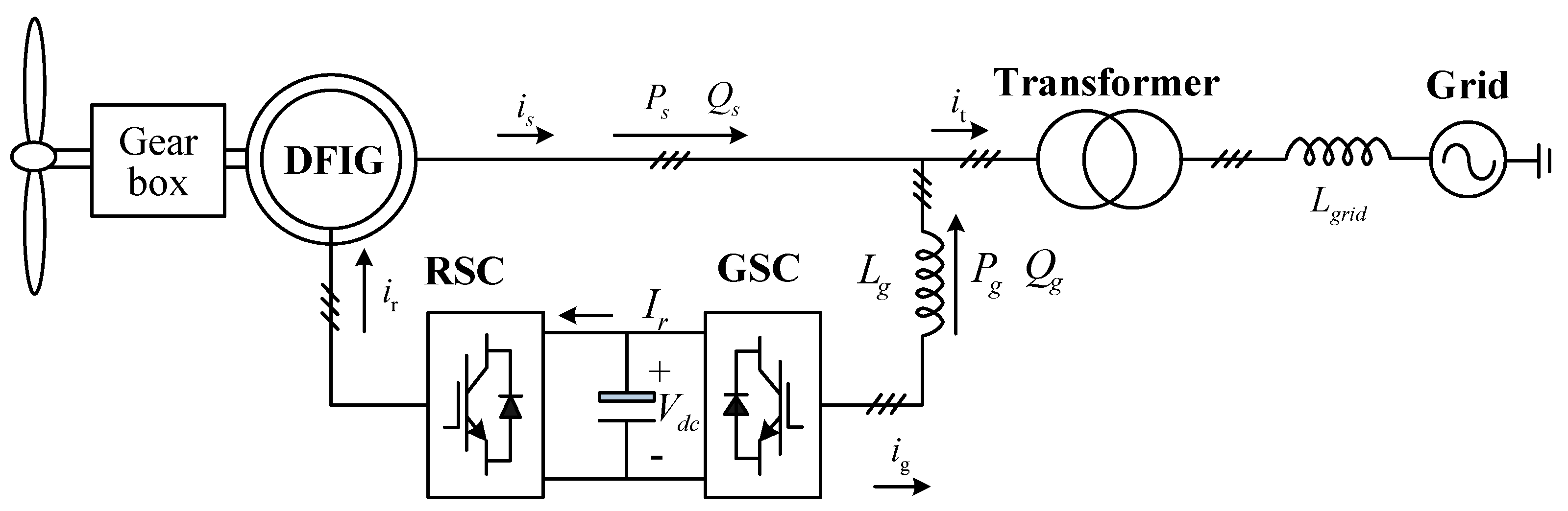
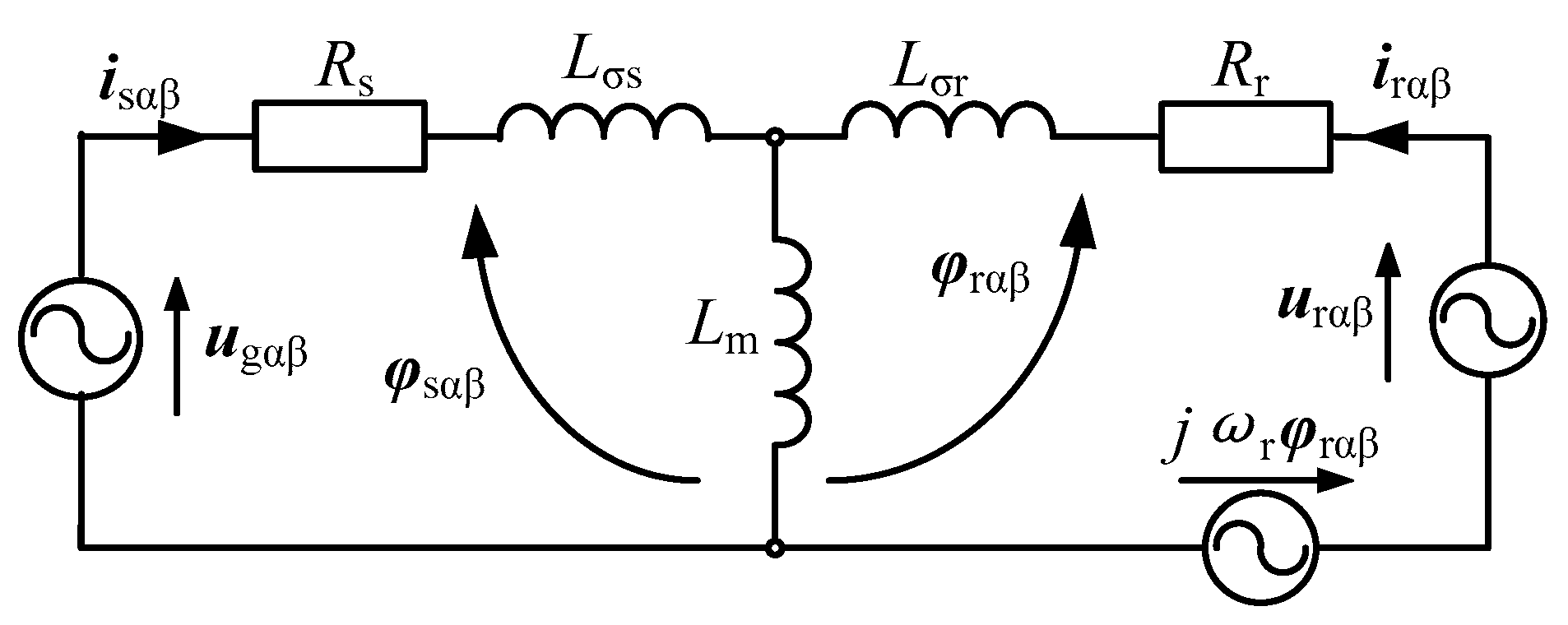
2.1. Sliding Mode Control of DFIG (RSC)
The DFIG equivalent circuit in the αβ frame is shown in Figure 2.
Figure 2.
DFIG equivalent circuit in the stationary αβ reference frame.
In order to regulate the active power and reactive power directly, the instantaneous power errors are defined as the DFIG’s state variables xre = [xrep xreq]T
where, xr = [Ps Qs]T; = [ ]T.
Then, according to the mathematical model, the behavior of the DFIG can be described by the following state-space form
where, δ = 1/(σLm); ζα = 2ωugβ ± 6ωugβ5 − 6ωugβ7, ζβ = −2ωugα − 6ωugα5 − 6ωugα7, which are related to the unbalanced and harmonic voltage; fr is the known disturbance of system; due to the ζα and ζβ are unknown items without the unbalanced and harmonic separation, dr is the unknown disturbance. And dr contains ac components at the frequencies of 2ω, 4ω, 6ω, 8ω and 12ω produced by the corresponding currents and voltages. The AC components at the frequencies of 2ω and 6ω are produced by the fundamental, unbalanced, 5−, 7+ harmonics currents and voltages. While the ac components at the frequencies of 4ω, 8ω and 12ω are produced by the unbalanced, 5−, 7+ harmonics currents and voltages. Thus, the ac components at the frequencies of 4ω, 8ω and 12ω can be neglected compared to the ac components at the frequencies of 2ω and 6ω.
In the conventional SMC, the sliding surface contains a proportional and an integral item, which provides accurate tracking on dc reference and rejection to dc disturbance. However, the AC errors will arise when the tracking reference or disturbance is the AC component. In order to provide sufficient tracking precision, multi-resonant items are added to the conventional integral sliding surface, which can be called “MRSMC”. Then, the DFIG’s sliding surfaces Sr = [Srp Srq]T are defined as follows
where krs is the integral coefficient related to dc error elimination; kri (i = 2, 6) is the resonant coefficient related to ac error elimination; εc is related to cutoff frequency and inserted into the resonant part to increase its frequency bandwidth. It should be pointed out that, due to the most parts of disturbance dr are the AC components at the frequencies of 2ω and 6ω, the added resonant regulators are tuned at the frequencies of 2ω and 6ω.
According to the condition of the equivalent control, viz. dSr/dt = 0, the equivalent controls, which provide sufficient regulation under ideal conditions, are derived as
When disturbances arise, the system will drift from sliding surface only with the equivalent control. The switching control must be added for disturbance rejection. To weaken the chattering phenomenon, the sign functions is replaced by saturation functions sat() in this paper. Consequently, the switching controls are
where, kru = [kru1 0; 0 kru2]; kru1 and kru2 are positive control gains; λ is the width of boundary layer in RSC.
Finally, the voltages to be applied to the rotor winding are
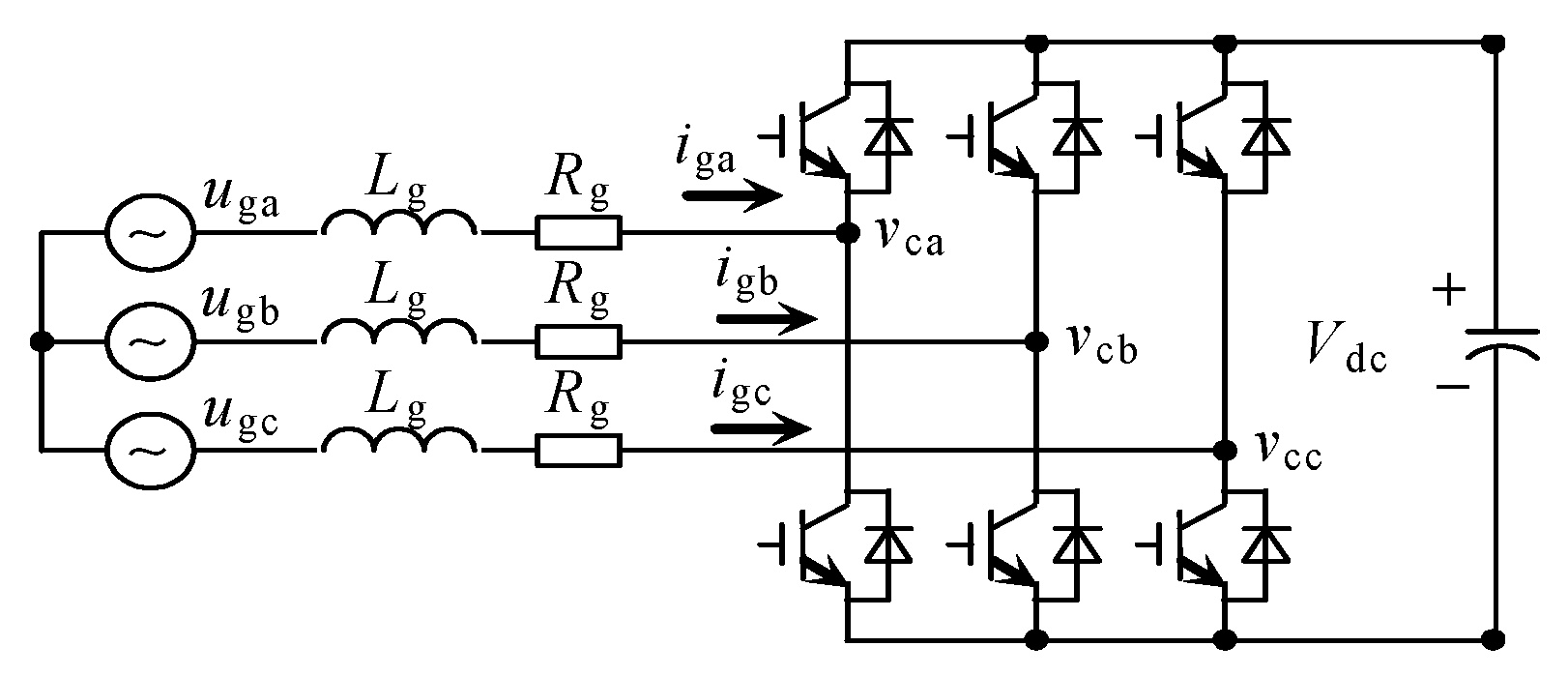
2.2. Sliding Mode Control of GSC
The circuit scheme of GSC is shown as Figure 3. Similar to RSC, in order to control the active power and reactive power directly, let us define the state variables of the GSC xge = [xgep xgeq]T as
where, xg = [Pg Qg]T; = [ ]T.
Figure 3.
Circuit scheme of grid connect converter.
Thus, according to the mathematical model, the behavior of the GSC is described as
where, fg is the known disturbance; dg is the unknown disturbance pulsating at the frequencies of 2ω and 6ω.
The method followed is similar to that described in Section 2.2. Thereby, the GSC’s sliding surfaces Sg = [Sgp Sgq]T are defined as following
where kgs is the integral coefficient; kgi (i = 2, 6) is the resonant coefficient; εc is related to cutoff frequency.
According to the condition of the equivalent control, viz. dSg/dt = 0, the equivalent controls of GSC are derived as
According to control law, the switching controls of GSC are
where, kgu = [kgu1 0; 0 kgu2]; kgu1 and kgu2 are positive control gains in GSC.
Then the voltages to be applied to GSC are
3. Analysis of MRSMC Strategy
3.1. Stability and Robustness
In sliding mode control design, a Lyapunov approach is usually used for deriving conditions on the control law that will drive the state orbit to the equilibrium manifold. The quadratic Lyapunov function is selected as
The time derivative of Wr and Wg on the state trajectories of (16) is given by
For stability to the sliding surfaces, it is sufficient to have dWj/dt (j = r or g). Outside the boundary layer of the sliding surface, the saturation functions of Sr/Sg are equal to their sign functions. In this condition, it is worth noting that if the positive control gains fulfill the following condition, viz.,
The time derivative of Lyapunov function dWj/dt (j = r or g) is definitely negative, which means that the system state moves asymptotically toward to the sliding surface outside the boundary layer. Hence, the system features strong robustness and is insensitive to variations of system parameters and external disturbances outside the boundary layer.
Inside the boundary layer of the sliding surface, if time derivative of Lyapunov function dWj/dt (j = r or g) is definitely negative, it is sufficient to have
It can be seen that the validity of (19) is affected by the forms of sliding surface Sj (j = r or g) and disturbance dj (j = r or g). The sliding surface of the MRSMC system is different from that in the ISMC system. And the unbalanced, 5− and 7+ harmonics distorted grid voltages will introduce the disturbances dj (j = r or g). The stability and tracking behavior of MRSMC and ISMC strategy with disturbances dj (j = r or g) will be investigated in Section 3.2.
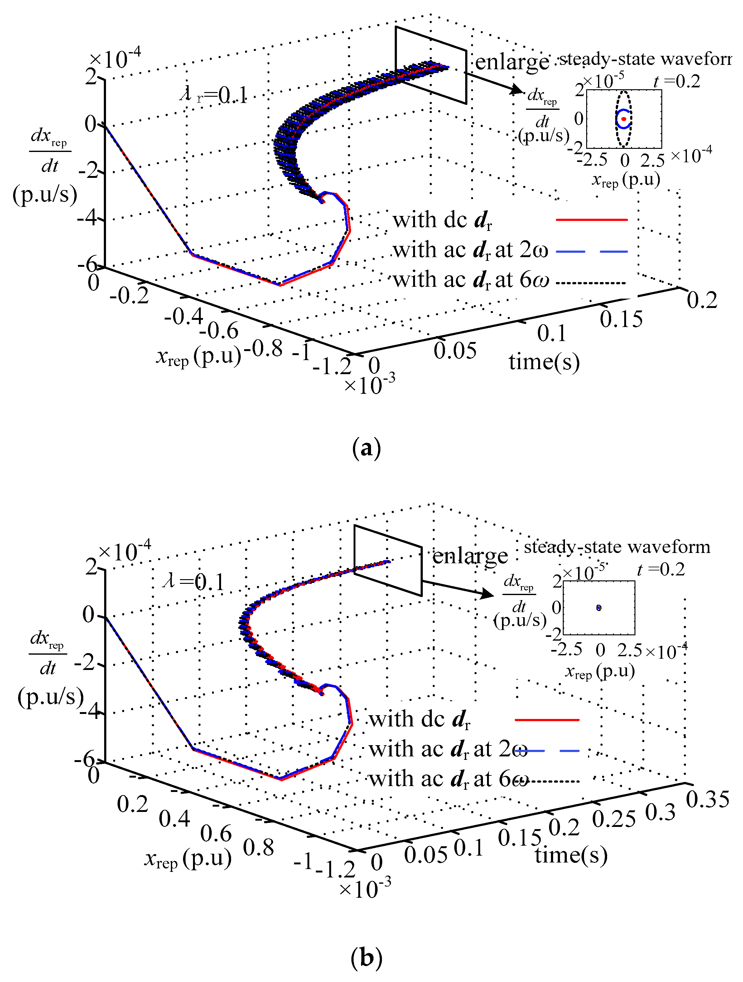
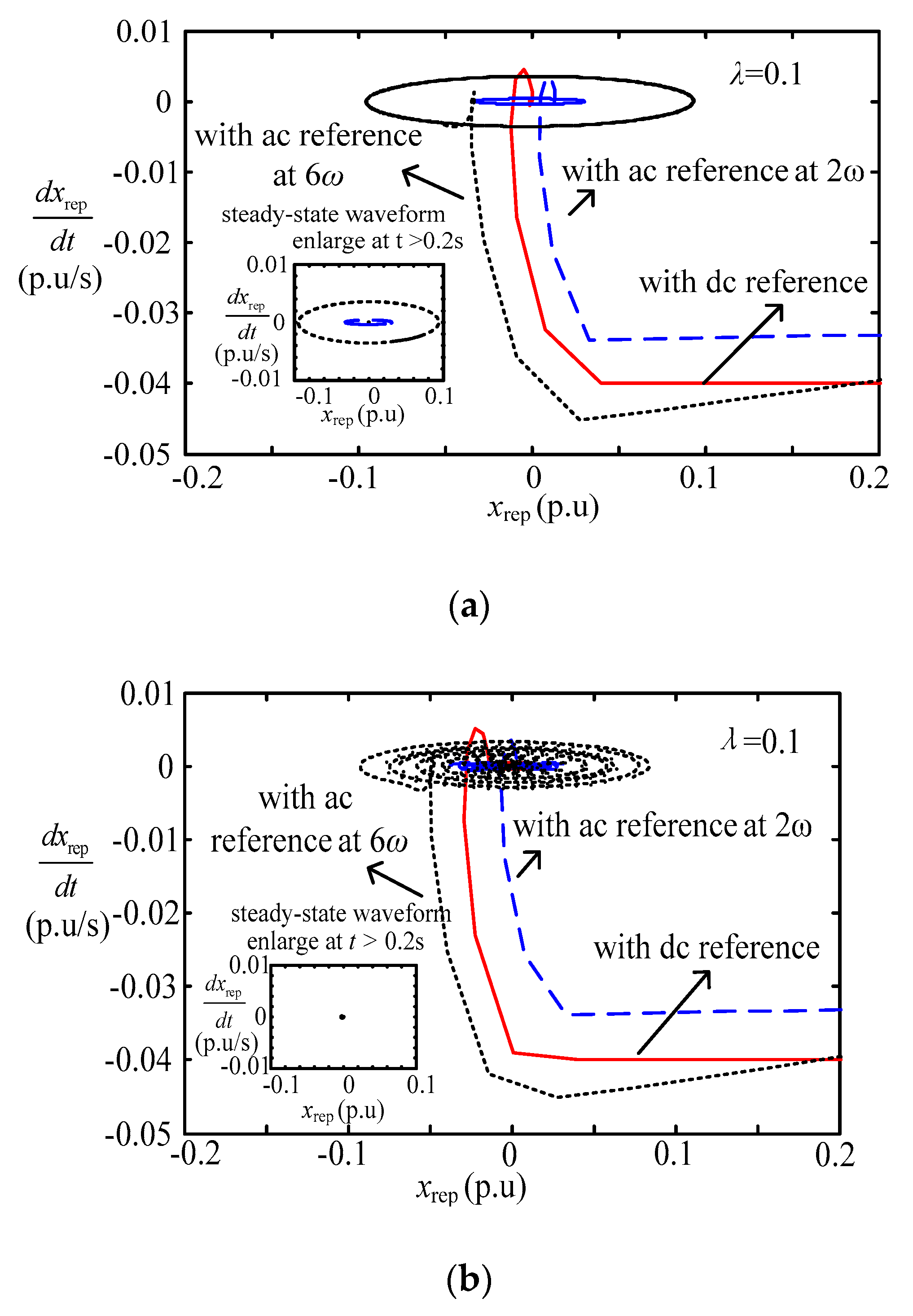
3.2. Tracking Behavior with Distorted Grid
The unbalanced, 5− and 7+ harmonics distorted grid voltages will introduce disturbance dj (j = r or g) into the DFIG control system, which mostly contains the ac components at the frequencies of 2ω and 6ω. If the voltages applied to the rotor and GSC are according to (8) and (15), the sliding surfaces functions with disturbance dj (j = r or g) are
The system described as (20) contains the saturation functions, and is a nonlinear system. In order to investigate the system dynamical behavior, the phase plane trajectory is adopted. Figure 4 shows the phase plane trajectories with dc disturbance and ac disturbances at the frequencies of 2ω and 6ω. It should be pointed out that, if the resonant coefficients kri and kgi (i = 2, 6) are zero, the control strategy will be the ISMC strategy. Thus, Figure 4a, in which the resonant coefficients kri (i = 2, 6) are equal to zero, shows the phase plane trajectory of ISMC. The resonant coefficient in Figure 4b is 20 and 50, and the Figure 4b shows the phase plane trajectory of MRSMC.
Figure 4.
Phase plane trajectory with disturbances. (a) Phase plane trajectory with disturbances of integral sliding mode control (ISMC); (b) Phase plane trajectory with disturbances of multi-resonant-based sliding mode control (MRSMC).
In Figure 4a, outside the boundary layer λr, the Srp moves toward to the boundary layer with the dc disturbance or ac disturbances dr, whereas inside the boundary layer, due to the integral action, the Srp achieves the origin only with the DC disturbance. With the ac disturbances, the Srp deviates from the origin, which means that it exists steady state errors with the ac disturbances. Thus, the ISMC strategy will degrade the system operation performance under unbalanced, 5− and 7+ harmonics distorted grid voltage conditions. In Figure 4b, outside the boundary layer, the Srp moves toward to the boundary layer regardless of disturbances. Inside the boundary layer, with the integral action and resonant action, the Srp achieves the origin regardless of the dc or ac disturbances, which means the steady state errors can be removed with the MRSMC. Thus, the MRSMC strategy features rejection on disturbances, and is insensitive to the distorted grid voltage. The analysis on phase plane trajectories of xgeq, xgeq and xreq are similar as xreq, which points out the similar conclusion.
In order to analyze the tracking precision on dc and ac references with ISMC and MRSMC, the phase plane trajectory with different tracking references were investigated. According to control laws and the DFIG and GSC’s equivalent circuits, the relationships of tracking references (j = r or g) and tracking error xje (j = r or g) are
According to (21), the phase plane trajectory of xgep with ISMC and MRSMC are shown as Figure 5a,b. Under unbalanced and 5− harmonics and 7+ harmonics distorted grid voltage conditions, the tracking references will contain the ac components at the frequencies of 2ω and 6ω. Thus, Figure 5 shows the phase plane trajectories with the DC reference and AC references at the frequencies of 2ω and 6ω.
Figure 5.
Phase plane trajectory with different tracking reference. (a) Phase plane trajectory with different tracking references of ISMC; (b) Phase plane trajectory with different tracking references of MRSMC.
Outside the boundary layer, in both Figure 5a,b, the xgep moves toward to the boundary layer regardless of the dc reference and ac references. Inside the boundary layer, the xgep deviates from the origin with the ac disturbances in Figure 5a. However, the xgep achieves the origin with the ac disturbances in Figure 5b. It implies that with the ISMC strategy, it will exist steady state errors under unbalanced, 5− harmonics and 7+ harmonics distorted grid voltage conditions. However, the accurate tracking on both dc and ac references at the frequencies of 2ω and 6ω of the proposed MRSMC strategy is verified. The analysis on phase plane trajectories of xgeq, xrep and xgeq are similar as xgep, which points out the similar conclusion.
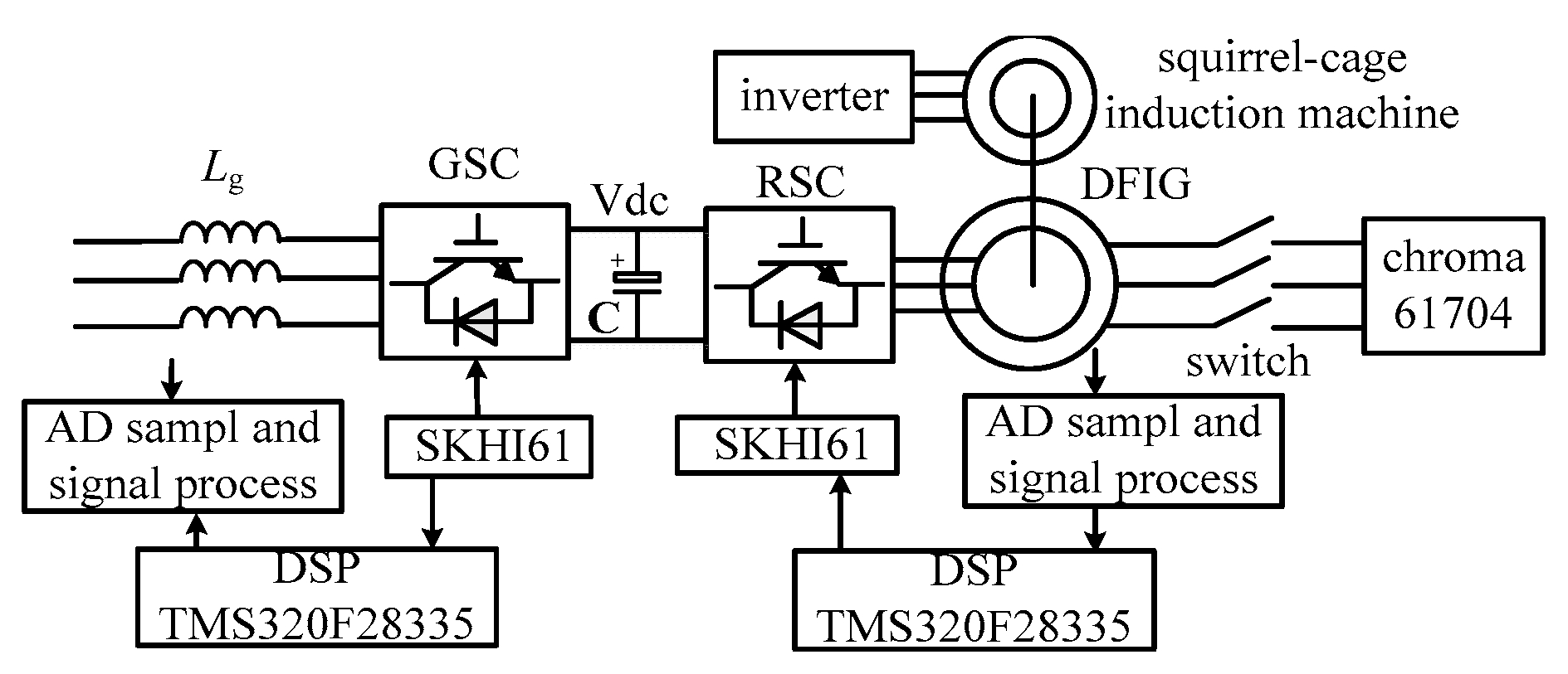
4. System Implementation
4.1. Active and Reactive Power References
Under unbalanced and distorted grid voltage conditions, not only the system total current will be distorted, but also the system power, DFIG torque and dc-link voltage will pulsate. To satisfy the demand of accessing network, the system total currents must be sinusoidal. Both the target of RSC and GSC are set to eliminate currents’ unbalanced and harmonic components. Thus, the references of stator active and reactive power , are derived as
where = + ; Pecom, Qecom are the commands of stator average active and reactive power.
Similarly, the references of GSC active and reactive power , are
where, Pecom and Qecom represent the commands of the GSC average active and reactive power.
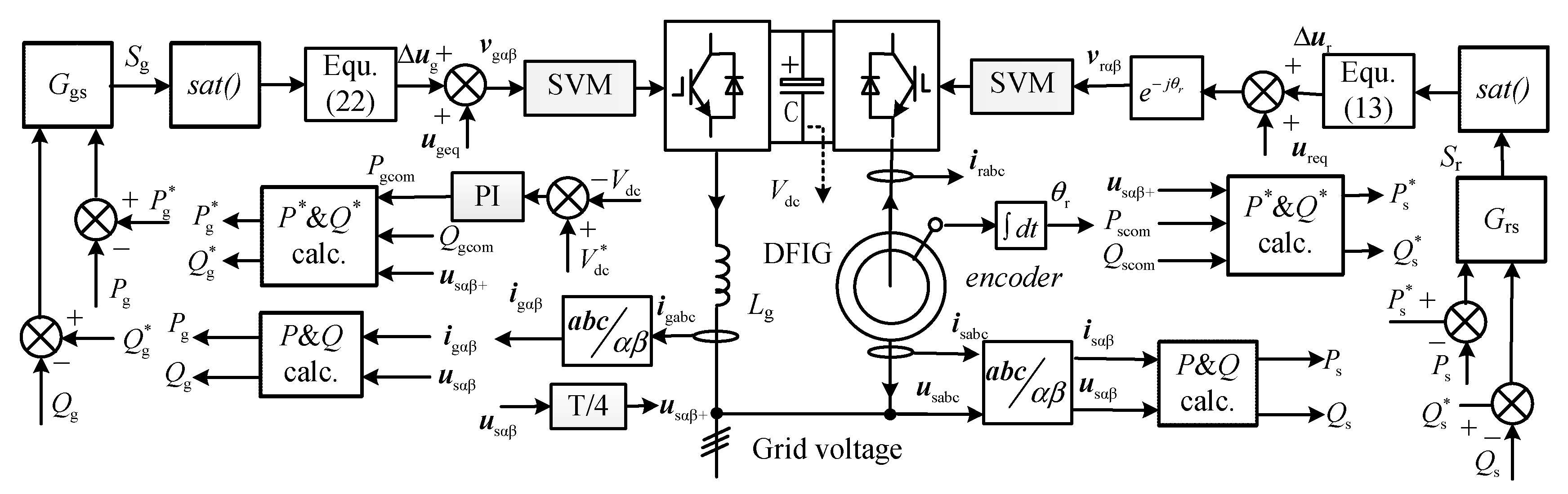
4.2. MRSMC System Implementation
Figure 6 shows the schematic diagram of the proposed MRSMC strategy for a DFIG system. The dc-link voltage was controlled by a PI controller in GSC, which produces the command of the GSC average active power Pgcom. As shown, the active and reactive powers in both RSC and GSC were regulated by the developed MRSMC in the αβ frame. It should be noted that the control strategy does not require any synchronous coordinate transformations as well as angular information of grid voltage.
Figure 6.
Schematic diagram of MRSMC for a DFIG system.
However, it can be seen from (23) that the fundamental grid voltage is necessitated. This paper is to delay the input signal by a quarter of the fundamental frequency period T1 [8] as follows
Figure 7 shows experimental results of the T1/4 delay technique, in which the grid voltage was ideal before t0 and contained 6.13% unbalanced, 3.5% 5− and 2.6% 7+ harmonic voltage. From the results, the fundamental voltage was separated from the distorted grid voltage within 0.005 s, which validated the effectiveness of the T1/4 delay technique.
Figure 7.
Experimental results of the T1/4 delay technique.
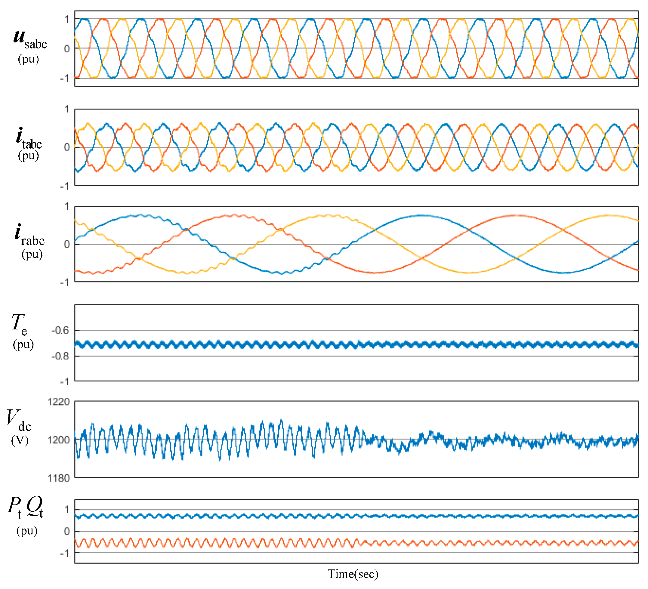
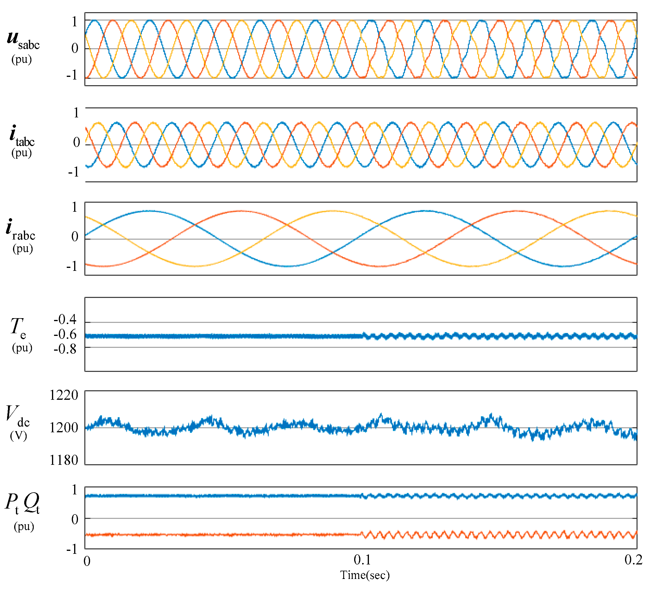
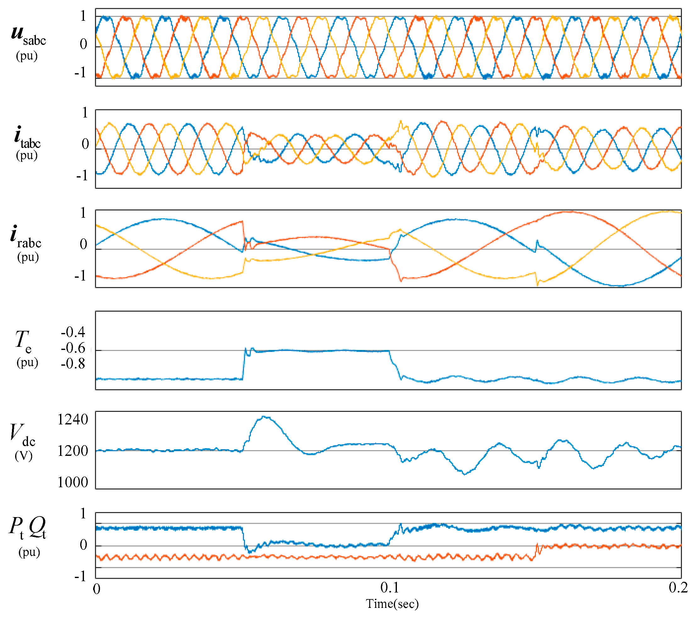
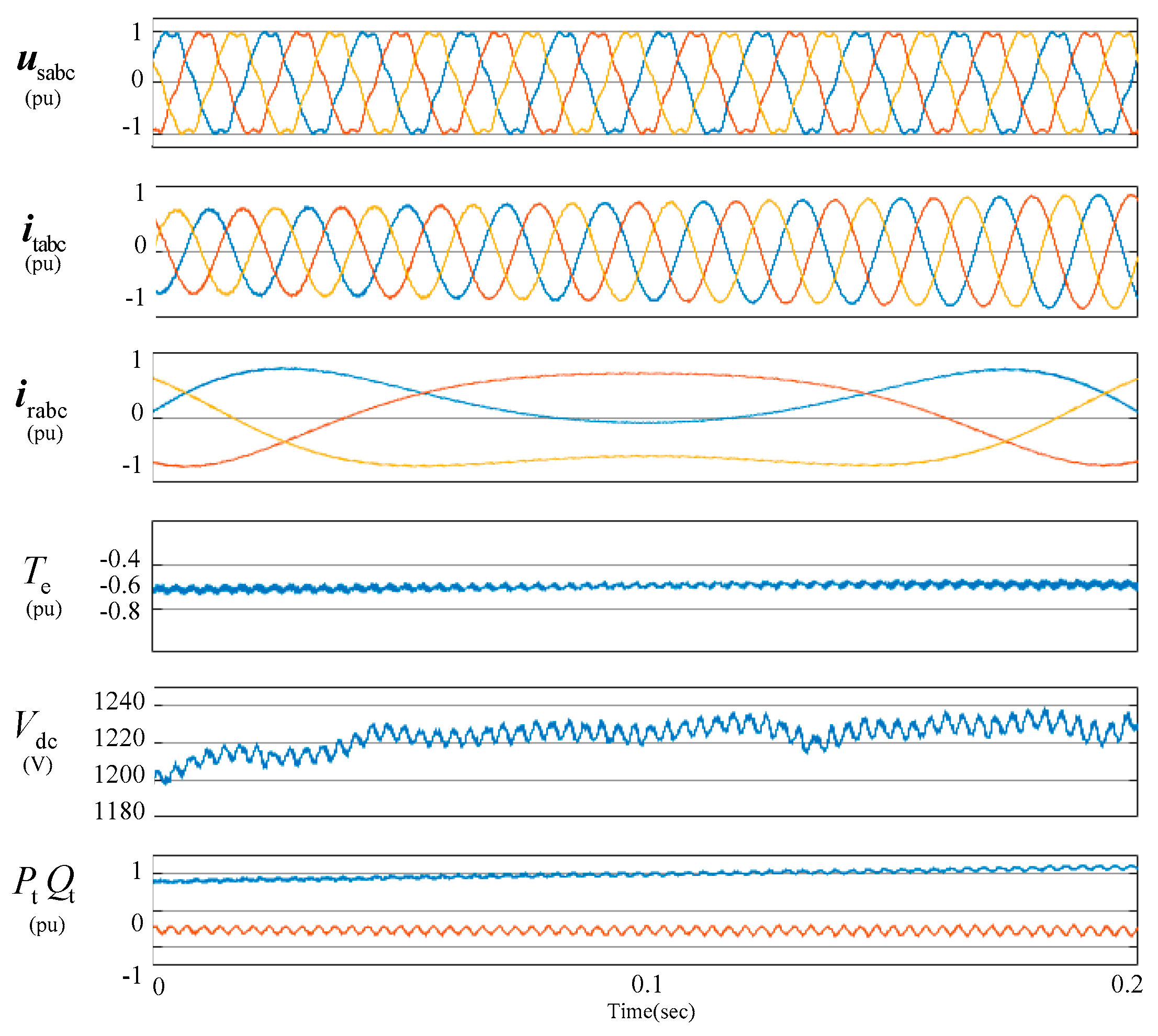
5. Simulation Results
In order to verify the MRSMC strategy for a DFIG system, a simulation model of a 2 MW DFIG wind power system is built on Matlab/Simulink. The system is rated at 2 MW with its parameters given in Table 1. The power system is modeled by a grid impedance and a voltage source, see in Figure 1. The grid impedance in the model is Lgrid = 0.004 H, which is related to the short-circuit ratio of power system. The distorted grid voltage of the following figs all contains 5% 5th harmonics and 5% 7th harmonics.
Table 1.
Parameters of The Simulation Model.
Comparative tests between the conventional ISMC and the MRSMC strategies for the DFIG system with distorted grid voltage were shown in Figure 8. The GSC reactive power command was set to 0.0 pu; the commands of stator’s active and reactive power were 1.0 pu and 0 pu. Table 2 shows the system total current harmonics in Figure 8, from which, it can be seen, when conventional ISMC is adopted, the total currents would contain 6.53% 5th and 6.50% 7th harmonics, and total harmonic distortion (THD) of total currents was 9.71%; while the proposed MRSMC is adopted, the THD of total currents was reduced to 3.14%, and the 5th and 7th harmonic of total current was reduced to 0.65% and 0.64% respectively. It can be validated that due to the introduction of multi-resonant items in the sliding surface, the tracking behave of the MRSMC is more accurate than ISMC, and the better suppression of current harmonics can be guaranteed.
Figure 8.
Simulation results of the MRSMC and ISMC for a DFIG system under distorted grid voltage.
Table 2.
Fast Fourier transform (FFT) of currents in Figure 8. ISMC: integral sliding mode control; MRSMC: multi-resonant-based sliding mode control.
Figure 9 shows the simulation results of the MRSMC strategy for a DFIG wind power system. In this fig, the grid voltage was ideal before 0.1 s and distorted after 0.1 s. It can be seen that, when the grid voltage harmonics appeared suddenly, the system achieved steady status quickly.
Figure 9.
Simulation results of the MRSMC for a DFIG system.
Figure 10 show the simulation results of the MRSMC strategy with power command change suddenly. In Figure the stator active power command was changed from 1 pu to 0.0 pu at 0.05 s, and from 0.0 pu to 1 pu at 0.1 s; the reactive power command was changed from 0 pu to 0.5 pu at 0.15 s, and from −0.5 pu to 0.5 pu at 0.15 s. In the fig, the total currents were sinusoidal, even at the moment of power setting change. The active power or the reactive power followed their command within 0.02 s. It can be validated that, the dynamic of the proposed MRSMC.
Figure 10.
Simulation results of the MRSMC with power command change.
Figure 11 shows the simulation results of the MRSMC strategy with rotor speed variation. It can be seen that the system maintains superb performance under this condition, which validated the good dynamic response of the proposed MRSMC.
Figure 11.
Simulation results of the MRSMC with continuous variation of rotor speed.
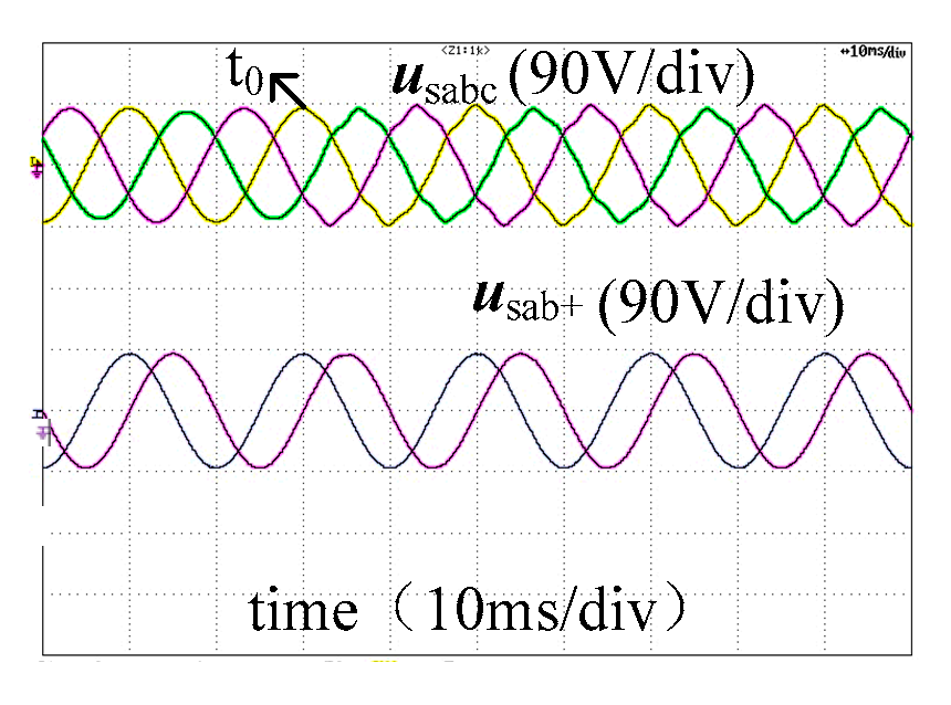
6. Experimental Results
In order to verify the performance of the proposed strategy further, experimental tests on a 1 kW DFIG system were performed. Figure 12 schematically shows the tested rig. The DFIG is driven by a squirrel-cage induction machine as the wind turbine. Both the GSC and RSC were controlled by a TM320F28335 digital signal processor. Table 3 shows the system parameters. The Chroma 61,704 programmable three-phase voltage source is set up to simulate the unbalanced and harmonic distorted power grid. It was found during the tests that there exhibited the unbalanced, 5− and 7+ harmonics in the three-phase voltage source detected being around 3.14%, 4.34% and 2.29%, respectively. During the experiment validation, the rotor speed was set to 800 r/min. In Figure 13, Figure 14 and Figure 15, the waveforms from top to bottom are (a) three-phase grid voltage ugabc (225 V/div); (b) three-phase rotor current irabc (4.7 A/div); (c) three-phase stator current isabc (4.6 A/div); (d) three-phase GSC current igabc (2.5 A/div); (e) three-phase total current itabc (12 A/div); (f) system reactive power Qt (624 Var/div); (g) DFIG’s torque Te (8.6 Nm/div) and DC-link voltage Udc (667 V/div), respectively.
Figure 12.
Configuration of test rig.
Table 3.
Parameters of The Tested System.
Figure 13.
Experimental results of the ISMC for a DFIG system.
Figure 14.
Experimental results of the MRSMC for a DFIG system.
Figure 15.
Experimental results of the MRSMC with active power step.
Figure 13 and Figure 14 show the experimental result of the DFIG wind power system with ISMC and MRSMC, respectively. The current harmonics and torque pulsations are shown in Table 4. As listed in the Table 4, with the control of ISMC, the severely distorted total current would be produced, i.e., 27.7% unbalanced component, 10.56% 5th and 3.58% 7th harmonics; the electromagnetic torque pulsations would be 0.27 N·m. Therefore, it can be found out that the DFIG operation performance would be severely degraded with ISMC under distorted grid voltage condition. Whereas, with the control of MRSMC, the unbalanced, 5th and 7th harmonics components of system total current would be reduced to 3.81%, 2.42% and 0.24%, respectively; the electromagnetic torque pulsations would be reduced to 0.096 N·m. Thus, it can be validated that, with the MRSMC, the suppression of total current harmonics and electromagnetic torque pulsations would be better than that with conventional ISMC, under distorted grid voltage conditions.
Figure 15 shows the experimental results of the MRSMC strategy with active power command change suddenly. In this fig, the total active power command was changed from −0.75 pu to 0.0 pu at t1. It can be seen, the total currents were sinusoidal and the DFIG torque was stable, even at the moment of total active power command change, and the active power followed the command within 0.05 s. It can be validated the satisfactory dynamic of the control system.
7. Conclusions
In this paper, the difficulty to reduce the impact of the unbalanced and harmonic distorted grid voltage on the DFIG system by using the conventional integral sliding mode control was proven. Then, multi-resonant items were added to the conventional integral sliding surface, and a multi-resonant-based sliding mode control (MRSMC) strategy for the DFIG-based wind power system was proposed. Not only the rejection on the unbalanced 5th and 7th harmonic grid voltages, but also the accurate tracking on both DC and AC references at the frequencies of 2ω and 6ω of the proposed MRSMC strategy were verified by the phase plane trajectory. To remove the harmonics of the system’s total current and the majority of the DFIG’s electromagnetic torque pulsations under unbalanced and harmonic distorted grid voltage conditions, the active power and reactive power commands in both RSC and GSC were given. Finally, with the control of MRSMC, the operating reliability and system total current quality of the DFIG wind power system were enhanced. The simulation and experimental results validated the effectiveness of the proposed MRSMC strategy for a DFIG wind power system.
Author Contributions
Y.Q. and Y.H. conceived and designed the experiments; Y.Q. performed the experiments; Y.Z. analyzed the data; L.H. contributed analysis tools; Y.Q. wrote the paper.
Funding
This research was funded by Zhejiang Provincial Natural Science Foundation of China, grant number LQ18E070001.
Conflicts of Interest
The authors declare no conflict of interest.
Abbreviations
| ug, ig | GSC output voltage and current vectors. |
| ur, ir, is | Rotor voltage and current vectors, stator current vectors. |
| , | Stator, rotor flux linkage vectors. |
| ω, ωr | Grid and rotor angular frequencies. |
| Pe, Ps, Qs | Electromagnetic power, stator output active and reactive powers. |
| Pg, Qg | GSC output active and reactive powers. |
| Ls, Lr, Lm | Stator, rotor self- inductances, mutual inductance. |
| Rs, Rr | Stator, rotor resistances. |
| Lg, Rg, C | GSC inductance and resistance, the capacitance of the dc link. |
| Ir, it | The load current of the rotor side, system total current vectors. |
| Subscripts | |
| α, β | Stationary α, β axis. |
| +, −, 5−, 7+ | Fundamental, unbalanced, 5− and 7+ -order components. |
| Superscripts | |
| * | Reference value for controller. |
| ∧ | Conjugate complex. |
References
- Energinet, D.K. Technical Regulation 3.2.5 for Wind Power Plants with a Power Output Greater than 11 kW. September 2010. Available online: http://www.energinet.dk (accessed on 1 October 2014).
- Grid Code-High and Extra High Voltage; E.ON Netz GmbH: Bayreuth, Germany, August 2003.
- Voltage Characteristics of Electricity Supplied by Public Distribution System, European Standard EN50160 (2007); CENELEC: Brussels, Belgium, 2007.
- Singh, G.K. Power system harmonics research: A survey. Eur. Trans. Electr. Power 2007, 19, 151–172. [Google Scholar] [CrossRef]
- Kiani, M.; Lee, W.J. Effects of voltage unbalance and system harmonics on the performance of doubly-fed induction wind generators. IEEE Trans. Ind. Appl. 2010, 46, 562–568. [Google Scholar] [CrossRef]
- Xu, H.; Hu, J.; He, Y. Operation of Wind-Turbine-Driven DFIG Systems Under Distorted Grid Voltage Conditions: Analysis and Experimental Validations. IEEE Trans. Power Electron. 2012, 27, 2354–2366. [Google Scholar] [CrossRef]
- Phan, V.-T.; Lee, H.-H. Performance Enhancement of Stand-Alone DFIG Systems with Control of Rotor and Load Side Converters Using Resonant Controllers. IEEE Trans. Ind. Appl. 2012, 48, 199–210. [Google Scholar] [CrossRef]
- Liu, C.; Blaabjerg, F.; Chen, W.; Xu, D. Stator Current Harmonic Control with Resonant Controller for Doubly Fed Induction Generator. IEEE Trans. Power Electron. 2012, 27, 3207–3220. [Google Scholar] [CrossRef]
- Leon, A.E.; Mauricio, J.M.; Solsona, J.A. Ride-Through Enhancement of DFIG-Based Wind Generation Considering Unbalanced and Distorted Conditions. IEEE Trans. Energy Convers. 2012, 27, 775–783. [Google Scholar] [CrossRef]
- Song, Y.; Nian, H. Modularized Control Strategy and Performance Analysis of DFIG System Under Unbalanced and Harmonic Grid Voltage. IEEE Trans. Power Electron. 2015, 30, 4831–4842. [Google Scholar] [CrossRef]
- Hu, J.; Xu, H.; He, Y. Coordinated Control of DFIG’s RSC and GSC Under Generalized Unbalanced and Distorted Grid Voltage Conditions. IEEE Trans. Ind. Electron. 2013, 60, 2808–2819. [Google Scholar] [CrossRef]
- Utkin, V.I.; Güldner, J.; Shi, J.X. Sliding Mode Control in Electromechanical Systems; CRC Press: Boca Raton, FL, USA, 1999; pp. 115–130. [Google Scholar]
- Xu, L.; Cartwright, P. Direct active and reactive power control of DFIG for wind energy generation. IEEE Trans. Energy Convers. 2006, 21, 750–758. [Google Scholar] [CrossRef]
- Young, K.D.; Utkin, V.I.; Ozguner, U. A control engineer’s guide to sliding mode control. In Proceedings of the 1996 IEEE International Workshop on Variable Structure Systems, Tokyo, Japan, 5–6 December 2016. [Google Scholar] [CrossRef]
- Beltran, B.; Ahmed-Ali, T.; Mohamed, E. High-Order Sliding-Mode Control of Variable-Speed Wind Turbines. IEEE Trans. Ind. Electron. 2009, 56, 3314–3321. [Google Scholar] [CrossRef]
- Hu, J.; Nian, H.; Hu, B.; He, Y.; Zhu, Z.Q. Direct Active and Reactive Power Regulation of DFIG Using Sliding-Mode Control Approach. IEEE Trans. Energy Convers. 2010, 25, 1028–1039. [Google Scholar] [CrossRef]
- Hu, J.; Yuan, X. VSC-based direct torque and reactive power control of doubly fed induction generato. Renew. Energy 2012, 40, 13–23. [Google Scholar] [CrossRef]
- Evangelista, C.; Puleston, P.; Valenciaga, F.; Fridman, L.M. Lyapunov-Designed Super-Twisting Sliding Mode Control for Wind Energy Conversion Optimization. IEEE Trans. Ind. Electron. 2013, 60, 538–545. [Google Scholar] [CrossRef]
- Susperregui, A.; Itsaso Martinez, M.; Tapia, G.; Vechiu, I. Second-order sliding-mode controller design and tuning for grid synchronisation and power control of a wind turbine-driven doubly fed induction generator. IET Renew. Power Gener. 2013, 7, 540–551. [Google Scholar] [CrossRef]
- Martinez, M.I.; Susperregui, A.; Tapia, G.; Xu, L. Sliding-mode control of a wind turbine-driven double-fed induction generator under non-ideal grid voltages. IET Renew. Power Gener. 2013, 7, 370–379. [Google Scholar] [CrossRef]
- Chen, S.Z.; Cheung, N.; Wong, K.C.; Wu, J. Integral sliding-mode direct torque control of doubly-fed induction generators under unbalanced grid voltage. IEEE Trans. Energy Convers. 2010, 5, 356–368. [Google Scholar] [CrossRef]
- Shang, L.; Hu, J. Sliding-Mode-Based Direct Power Control of Grid-Connected Wind-Turbine-Driven Doubly Fed Induction Generators Under Unbalanced Grid Voltage Conditions. IEEE Trans. Energy Convers. 2012, 27, 362–373. [Google Scholar] [CrossRef]
- Martinez, M.I.; Tapia, G.; Susperregui, A.; Camblong, H. Sliding-Mode Control for DFIG Rotor- and Grid-Side Converters Under Unbalanced and Harmonically Distorted Grid Voltage. IEEE Trans. Energy Convers. 2012, 27, 328–339. [Google Scholar] [CrossRef]
- Hao, X.; Yang, X.; Liu, T.; Huang, L.; Chen, W. A Sliding-Mode Controller with Multiresonant Sliding Surface for Single-Phase Grid-Connected VSI With an LCL Filter. IEEE Trans. Power Electron. 2013, 28, 2259–2268. [Google Scholar] [CrossRef]
© 2019 by the authors. Licensee MDPI, Basel, Switzerland. This article is an open access article distributed under the terms and conditions of the Creative Commons Attribution (CC BY) license (http://creativecommons.org/licenses/by/4.0/).