Article

DC-Link Voltage Control of a Grid-Connected Solar Photovoltaic System for Fault Ride-Through Capability Enhancement

1
Department of Electrical Engineering, King Faisal University, Hofuf 31982, Saudi Arabia
2
Department of Electrical Engineering, Kalasalingam Academy of Research and Education, Krishnan Koil 626126, India
*
Author to whom correspondence should be addressed.
Appl. Sci. 2019, 9(5), 952; https://doi.org/10.3390/app9050952
Submission received: 11 January 2019 / Revised: 24 February 2019 / Accepted: 25 February 2019 / Published: 6 March 2019
(This article belongs to the Special Issue Control and Protection Issues of Grid-Tied Photovoltaic System)

Abstract

:
The high penetration level of solar photovoltaic (SPV) generation systems imposes a major challenge to the secure operation of power systems. SPV generation systems are connected to the power grid via power converters. During a fault on the grid side; overvoltage can occur at the direct current link (DCL) due to the power imbalance between the SPV and the grid sides. Subsequently; the SPV inverter is disconnected; which reduces the grid reliability. DC-link voltage control is an important task during low voltage ride-through (LVRT) for SPV generation systems. By properly controlling the power converters; we can enhance the LVRT capability of a grid-connected SPV system according to the grid code (GC) requirements. This study proposes a novel DCL voltage control scheme for a DC–DC converter to enhance the LVRT capability of the two-stage grid-connected SPV system. The control scheme includes a “control without maximum power point tracking (MPPT)” controller; which is activated when the DCL voltage exceeds its nominal value; otherwise, the MPPT control is activated. Compared to the existing LVRT schemes the proposed method is economical as it is achieved by connecting the proposed controller to the existing MPPT controller without additional hardware or changes in the software. In this approach, although the SPV system will not operate at the maximum power point and the inverter will not face any over current challenge it can still provide reactive power support in response to a grid fault. A comprehensive simulation was carried out to verify the effectiveness of the proposed control scheme for enhancing the LVRT capability and stability margin of an interconnected SPV generation system under symmetrical and asymmetrical grid faults.

Graphical Abstract

1. Introduction

The number of renewable energy sources connected to the public grid is increasing significantly, due to the deregulation of electric power distribution industries and environmental issues. Among these renewable sources, photovoltaic (PV) technology will play an important role in the future of electricity generation. In the past, PV sources were commonly used in isolated and stand-alone applications. Nowadays, PV systems are commonly connected to the public grid and the generated power is sold, with advantageous price ratings fixed by governmental policies. The high penetration of solar photovoltaic (SPV) systems has resulted in several technical problems in the grid. The grid codes (GCs) are strictly adhered to in order for grid-connected SPV systems to avoid adverse effects on the power system [1,2,3]. Among the grid codes, the low-voltage ride-through (LVRT) capability of solar PV is important. According to the widely adopted E.ON Netz GmbH code, the PV system should be kept connected to the grid during grid disturbances, to provide dynamic grid support [4]. Extensive studies have been performed on enhancement of the LVRT of SPV systems via hardware solutions. A direct current (DC)-breaking chopper circuit can be coupled across the DCL to satisfy the GC with respect to the LVRT [5]. However, this method requires additional components, and dissipates a large amount of power during the fault condition. In research by Al-Shetwi and Sujod [6] an alternative approach for LVRT enhancement was proposed, by connecting the energy storage system (ESS) with the DCL to avoid excess energy being applied to the DC-link capacitor. However, this control method not only increases cost, but also requires frequent maintenance. The insertion of a series dynamic braking resistor (SDBR) improves the voltage sag by introducing impedance at the fault point [7]. This approach will enhance the LVRT capability of the PV system. However, the selection of the optimal resistance value for the SDBR is a challenging task. In Sabir’s work [8], an LVRT capability enhancement scheme for a hybrid PV–fuel cell system is proposed, in which a dump load is inserted to maintain an active power balance, DCL voltage, and grid currents within their limits under fault conditions. The dump loads used in the system will increase the power loss on the system in this method. In Yang et al. [9], fault-current limiters (FLCs) are proposed to reduce DCL fluctuations. Additionally, a novel intelligent damping controller (NIDC) has been proposed for the static synchronous compensator (STATCOM) to enhance the transient stability of the hybrid power multi-system [10]. However, all of the above approaches involve additional hardware costs.
Looking for alternatives to the above hardware-based approaches, several studies have been performed to augment the LVRT of SPV systems by modifying the control strategies. In Wu et al. [11], an LVRT strategy based on positive and negative sequence control schemes is proposed for large-scale PV plants; however, the proper active power injection and the DC link over voltage control during a grid disturbance are not discussed widely. The active and reactive power control for grid balance of the PV system under a grid fault is proposed in the work by Bae et al. [12], however the DC-link over-voltage is not considered. In Yang et al. [13], an LVRT capability improvement strategy is proposed which is based on decreasing the output power delivery of the SPV system via controlling the DC–DC boost converter proportion compared to the level of voltage sag, so that the PV generation system can maintain the power balance during grid voltage differences. Simultaneously, the grid inverter delivers the specified reactive current to the grid according to the E.ON Netz GmbH code. However, the performance of the proposed control strategy in real environmental conditions, including variable irradiance and temperature, was not discussed. In Park and Park [14], a non-MPPT control scheme, called power-weakening control, was developed for excessive power conditioning. In the work by Nezhad et al. [15], a non-MPPT operation mode of a PV system considering the fault current limiting approach is explored. However, it did not focus on the controller performance under fault conditions. In Bak et al. [16], a modified second-order generalized integrator phase-locked loop (SOGI-PLL) scheme for enhancing the zero voltage ride-through (ZVRT) in a single-phase grid-connected PV system is proposed. Compared to enhanced phase-locked loop (EPLL), the SOGI-PLL approach is faster. However, in SOGI-PLL, overshoot is observed in the process of amplitude detection. In the research by Almeida et al. [17], a discrete-time LVRT controller is proposed for a proportional-integral (PI)-controller, in parallel with two modified digital resonant compensators, to mitigate the second-order harmonic voltage oscillation in the DC-link, as well as the positive sequence third-order harmonic current injection into the grid under asymmetrical fault conditions. This study does not discuss the proposed controller’s performance under symmetrical fault conditions. In Hong et al. [18], a radial basis function network (RBFN) MPPT controller is proposed, in order to achieve a fast and stable response for the real power control of a hybrid power generation system. This study demonstrated that an RBFN-based MPPT quickly stabilizes at the maximum power point after intense changes. In Ou and Hong [19], dynamic operation and control strategies for a micro-grid are analyzed. A GRNN (general regression neural network) with an improved PSO (particle swarm optimization) algorithm-based MPPT controller is developed to investigate the performance of the PV generation system under transient conditions. A comparison is made with the perturb and observe (P&O) method, which shows that the GRNN controller does not oscillate during tracking to save energy; on the other hand, the P&O method retains oscillating during tracking. It shows a better performance on both transient responses and stability. Unfortunately, these techniques can be costly and difficult to implement. Hence, this literature review infers that the purpose of LVRT enhancement cannot ignore MPPT control techniques.
In the work by Sadeghkhani et al. [20], a current and voltage-limiting strategy to enhance the LVRT capability of inverter-based micro grids (MGs) under symmetrical and asymmetrical faults is proposed. By fixing the current limiting factor (CLF) of the inductor, the current indirectly limits the inverter output voltage of the SPV inverter, and consequently no voltage limit is required in the inner current control loop as proposed in Perera et al. [21]. In the work by Ting-Chia Ou [22], a novel unsymmetrical faults analysis method based on the actual three phase models and the boundary conditions to develop completely the network characteristics of micro-grid distribution system (MGDS) is proposed. Two primary matrices (BI and ZV-BC), which are built from the topological characteristics of MGD networks, are used to achieve the power flow solutions. Test results show that the proposed method can achieve high accuracy and efficiency with a lower memory requirement, which could be a useful future smart grid application. A direct building algorithm for micro-grid distribution ground fault (MGDGF) analysis is proposed in [23]. The test results demonstrate that the proposed algorithm is suitable for MGDS, and the ill-conditioned problem that usually occurs in the traditional solution techniques can be avoided here.
To overcome the switching frequency limitation problem of the conventional boost converter, quadratic and double cascade boost converters for renewable energy application are proposed in the work by Boujelben et al. [24], which achieves better efficiency. The voltage control method of a cascaded step-up switched-capacitor converter (CSU–SCC) under a zero current switching (ZCS) operation and continuous conduction mode is proposed in Mousavi et al. [25], to achieve high voltage gain and reduce the number of components. In the work by Mousa et al. [26], a switched inductor multilevel boost converter for higher DC voltage applications is proposed, the main advantage of which is that the voltage stress on the switch is smaller. In the aforementioned schemes, the main drawbacks are the complexity of the control structure, and the need for more components which will increase cost. The choice of the most suitable boost converter to be used in a PV system is difficult to determine due to the fact that each boost converter has its own advantages and disadvantages, and the choice is highly application-dependent. Typically, a conventional boost converter is used in grid-connected SPV systems due to it having a simple structure and being easy to implement in practical systems, leading to lower costs. For this reason, in this work a conventional boost converter is considered. In general, the maximum power point tracking (MPPT) technique is used in SPV systems to increase the power obtained under all environmental conditions. The MPPT control technique works well during normal conditions, but the MPPT controller affects the system under faulted conditions. Furthermore, when a grid fault occurs, the point of common coupling (PCC) voltage goes down, which leads to a power imbalance on the inverter’s side, and this results in detachment of the inverter from the power grid according to the over voltage protection standard [27]. Thus, to protect the inverter while satisfying the GC, a novel control scheme must be developed with MPPT control for controlling DC–DC converters, and also to limit the output voltage to a safe value under both normal and fault conditions. Often, according to grid code requirements, the active and reactive power values are not appropriately satisfied by most of the existing LVRT schemes. This work attempts to enhance the LVRT capabilities of grid-connected SPV systems by controlling the DCL overvoltage, and realize reactive power and active power support based on GC requirements.
In reference to the aforementioned background, this work proposes a novel control scheme that controls the DCL voltage rise within standard limits, without imposing extra system costs under normal and fault conditions, by using two controllers. The control mechanism consists of an “MPPT” scheme and a “control without MPPT” scheme. The developed algorithm properly operates these controllers in the normal and fault conditions. When a grid fault occurs, the “control without MPPT” controller minimizes the active power injected into the grid, which will ultimately trigger the inverter to inject the required amount of reactive current into the power grid; the system then provides grid support and voltage recovery, while not exceeding the specified safe current value of the inverter. Compared to the existing methods, the proposed method can not only effectively reduce the DC-link over voltage during a grid fault, but also provide reactive power support to the grid according to the German E.ON grid code requirements, without using any extra hardware. Simulation studies were conducted to validate the effectiveness of the proposed control strategy.
This paper is organized as follows: Section 2 describes the grid-connected solar PV system. Section 3 explains the impacts of a fault on the grid-connected SPV system. Section 4 describes the proposed control strategies. Section 5 reports the simulation test findings and discussion. A comparison of the conventional and proposed strategies is given in Section 6. Finally, Section 7 presents our conclusions.

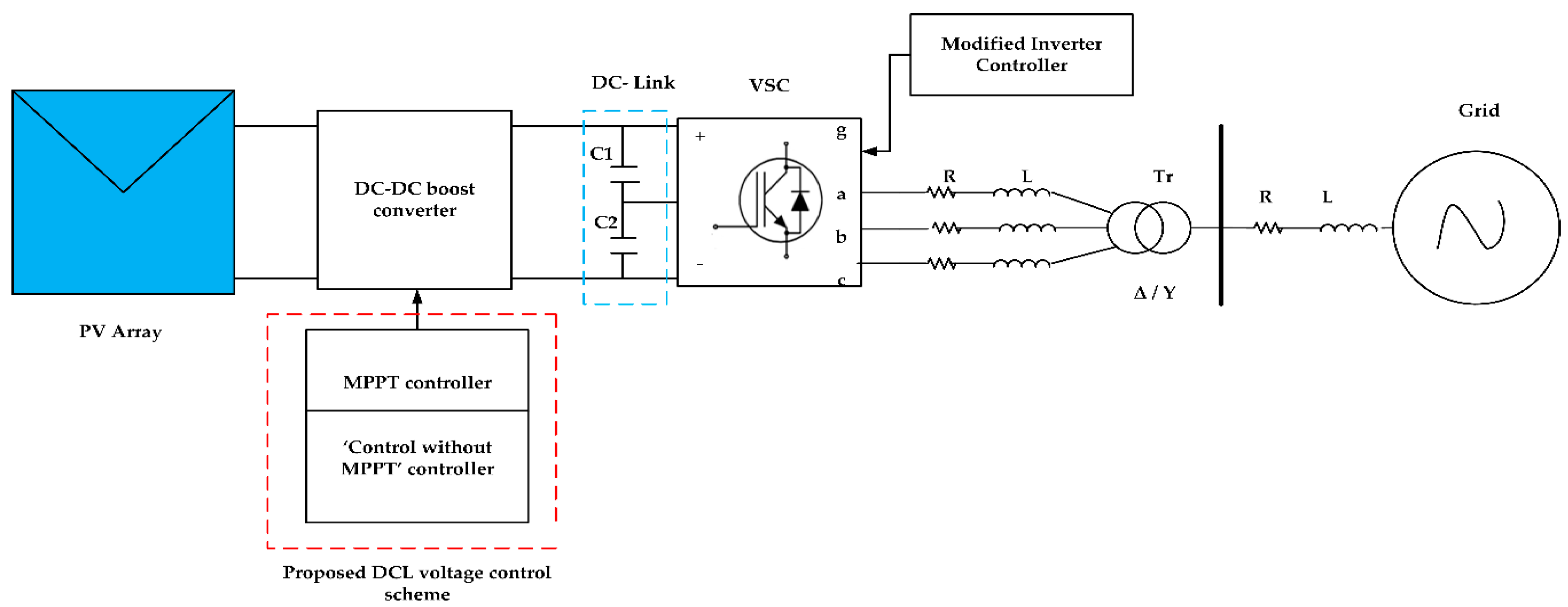
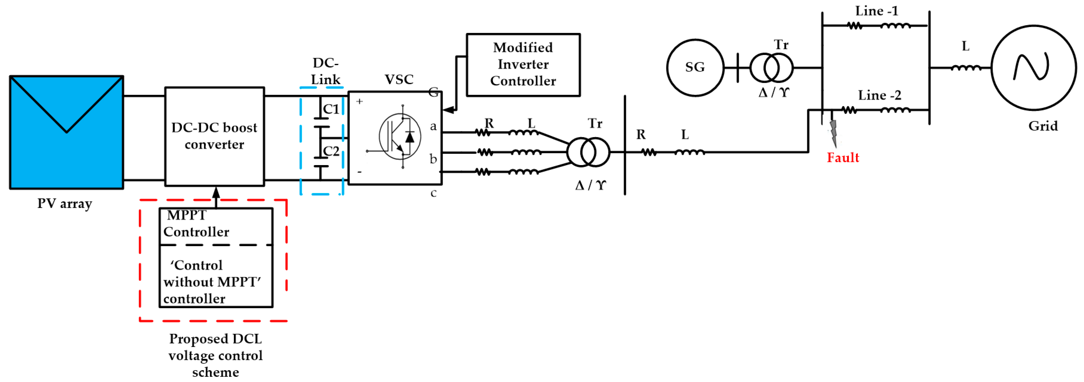
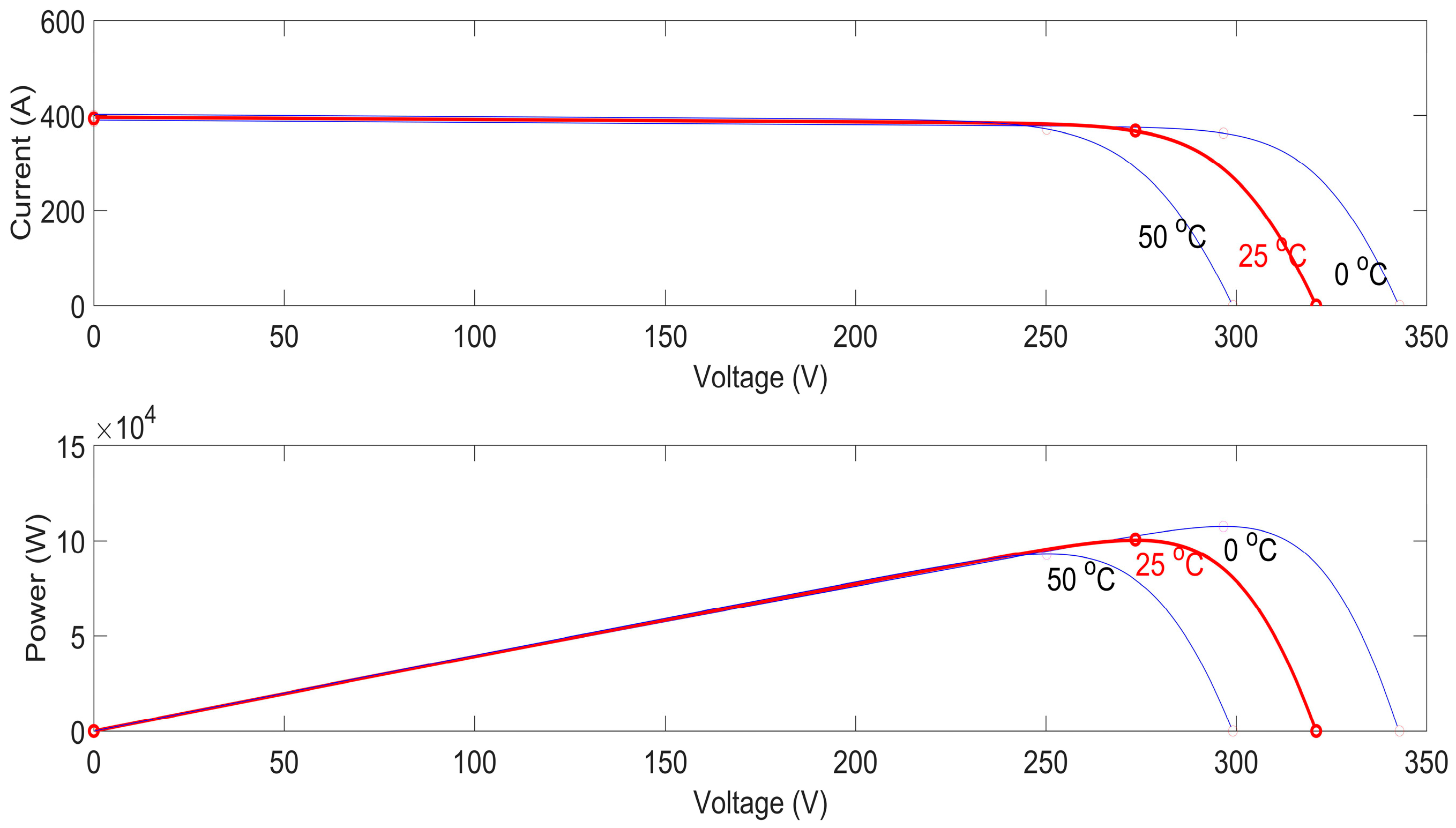
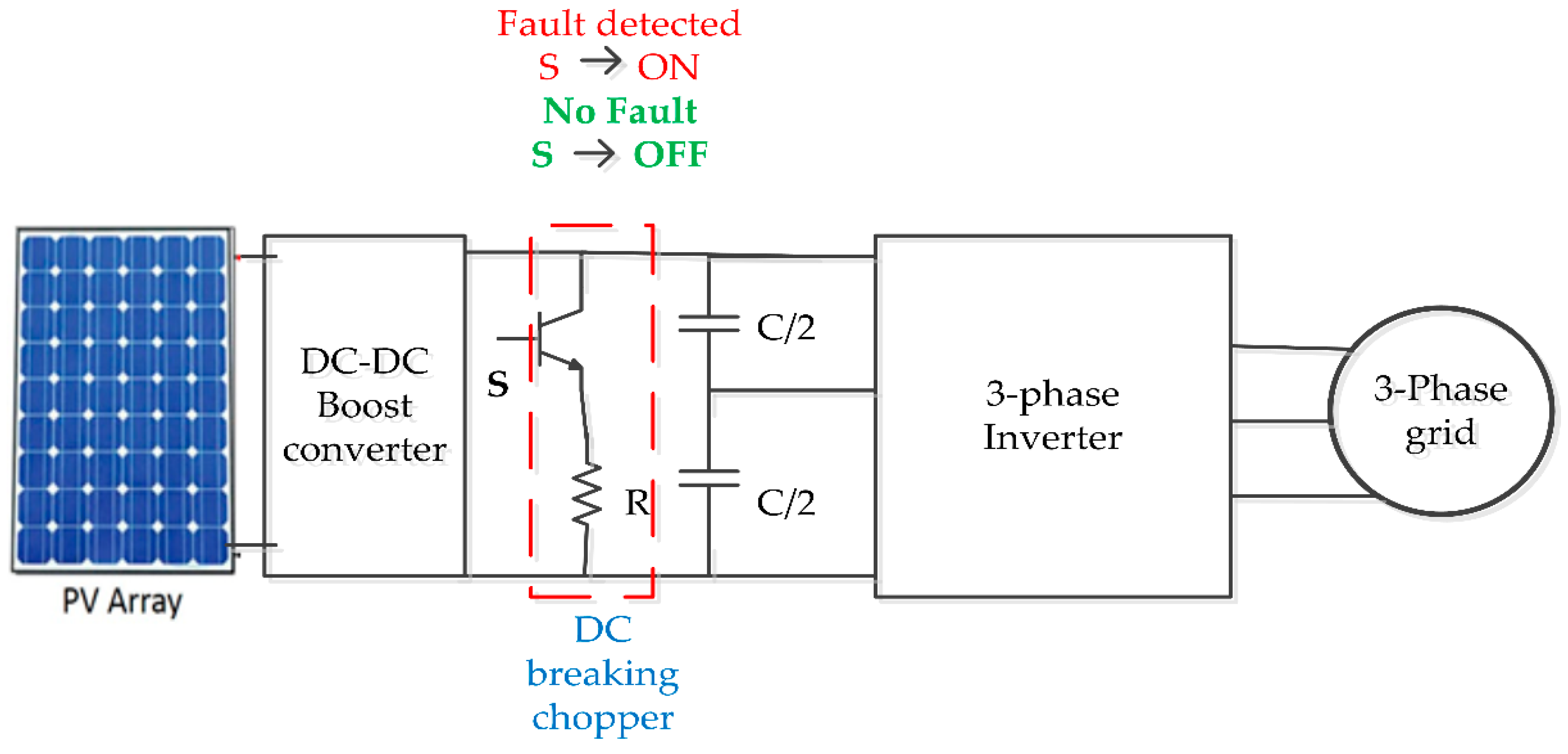
2. Grid-Connected Solar Photovoltaic (SPV) System

Figure 1 illustrates the schematic diagrams of the grid-connected PV system. Two-stage energy conversation systems are used in this work. The first stage of the energy conversion system consists of a PV array and a DC–DC converter, which boosts the relatively low SPV system voltage to match the inverter input voltage rating. The next stage consists of a voltage source converter (VSC) connected to the grid via an L-filter and a step-up transformer, to increase the inverter voltage to match the grid voltage [28]. The incremental conductance (IC) maximum power point tracker (MPPT) for the PV is implemented on the boost converter for extracting maximum power under normal conditiond. The “control without MPPT” controller is adopted under fault conditions. The inverter control scheme is modified to inject the required reactive current into the grid under fault conditions, by using the developed reactive power injection strategy.

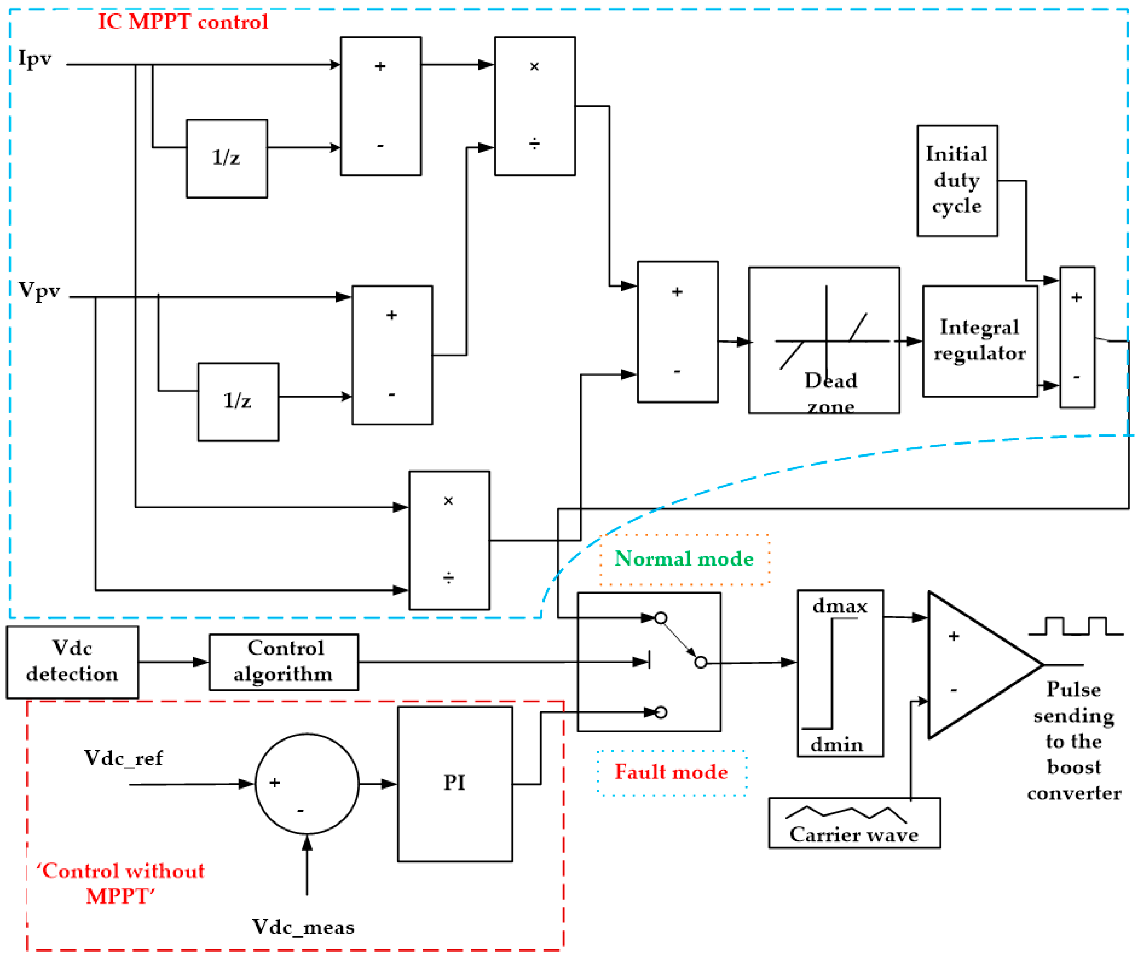
Direct Current–Direct Current (DC–DC) Boost Converter Model

As the voltage of PV arrays is not sufficient as input into the inverters, a DC–DC boost converter should be connected in order to increase the DC voltage under certain conditions. The structure of the boost converter is shown in Figure 2.
The input-output voltage relationship of the DC–DC converter is (1):
V in = V o ( 1 D )
where D is the duty cycle, Vin is the input voltage, and V0 is the output voltage.
The ripple voltage is:
V rip = Δ V o / V o
To reduce the ripple voltage, the pulse-width modulation (PWM) frequency of the pulse generator was reduced. However, we could not increase the frequency beyond a certain value because a higher frequency produces large energy losses in the circuit.

3. Impact of a Fault on the Grid-Connected SPV System

This work considers a two-stage grid-connected SPV (Figure 1). The total power flow of the system can be defined as follows [29]:
P spv = P DC   link + P g
where P DC _ link is the DC link power, Pg is the power inserted by the inverter to the grid, and Pspv is the PV power.
During normal operations:
P spv = P g = 3 V g rms I grms
where Vgrms and Igrms are the nominal RMS values of the phase voltage and phase current, respectively. Equation (4) shows that the DCL voltage can be maintained by keeping the PV array power (Pspv) equal to the power inserted by the inverter to the grid (Pg). We assume the power converter losses are neglected. However, under fault conditions, when voltage sag occurs on the PCC, it will not allow the power to be injected in the SPV system. The DC–DC boost converter using the MPPT control unit constantly obtains the maximum power from the SPV and injects it into the DCL. The inequality between the SPV-generated power and the power injected into the grid will sharply increase the DCL voltage. The fault condition is defined as follows:
( P spv P gf ) Δ T = P DCL Δ T = 1 2 C DC ( V 2 DCL _ f V 2 DCL )
where Pgf is the grid power at the fault, VDCL is the DCL voltage before the fault, VDCL_f is the DCL voltage at the fault period, ∆T is the fault period, and CDC is the DCL capacitance. VDCL_f is given as:
V DCL _ f = ( 2 ( Pspv 3 V g I g ) Δ T ) ) / C DC + V DCL 2
Equation (6) shows that the DCL voltage rise rate depends on the voltage sag level (Vg goes low during a fault) and the fault period ( Δ T ) . In the case of severe fault conditions, the voltage drops as the PCC decreases to a lower level, and longer fault duration causes a higher rise rate for the generated DCL voltage. Thus, without any protection scheme under any type of fault, it may violate the DCL over-voltage standard.

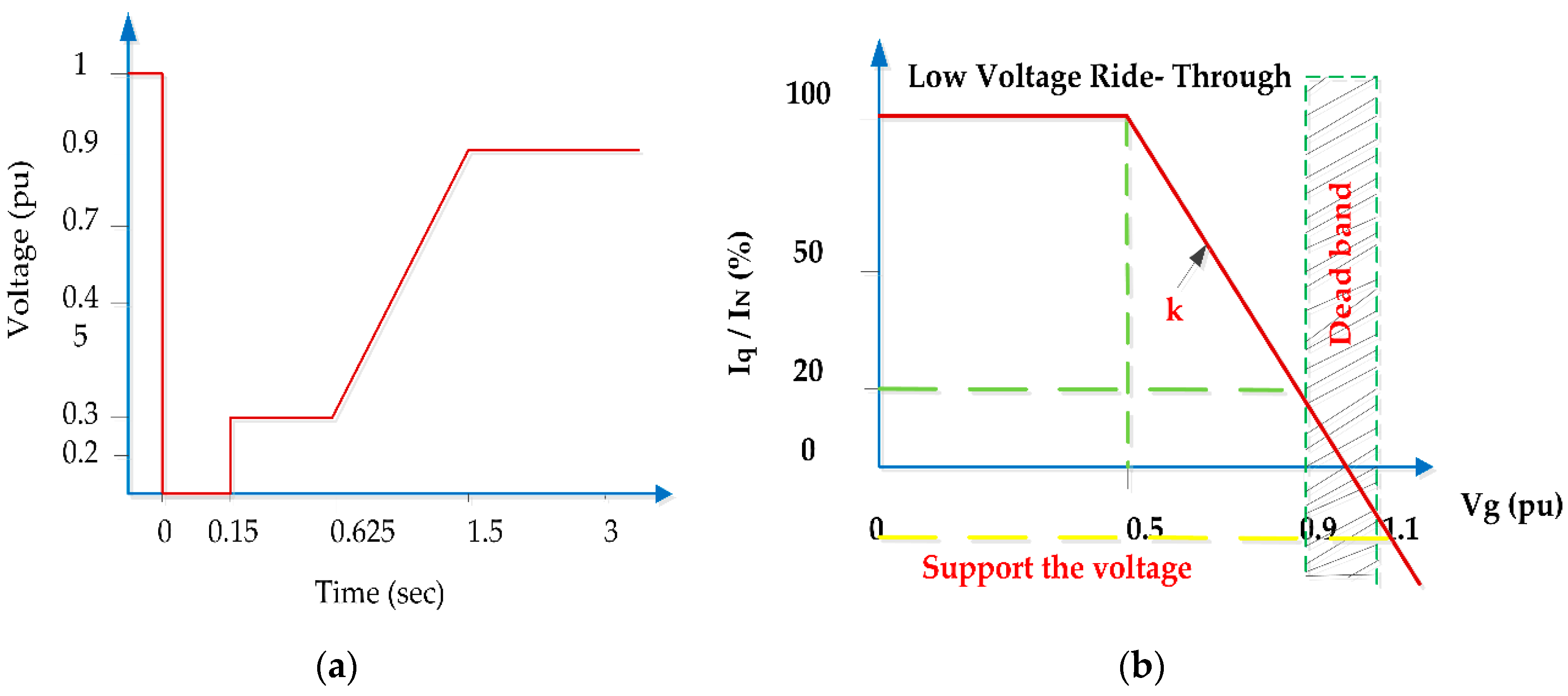
Low Voltage Ride-Through (LVRT) Capability of the SPV System

According to German E.ON grid code shown in Figure 3a, the SPV system should not be disconnected from the grid when the PCC voltage falls down to zero percentage of the nominal voltage for a period less than or equal to 0.15 s, and should recover to 90% of the voltage from its pre-fault level within 1.5 s from the occurrence of the voltage sag [30]. In addition, SPV systems should inject reactive current under fault conditions, depending on the voltage sag range and the inverter current rating capacity, to provide dynamic grid–voltage support according to the profile given in Figure 3b. According to the grid code (GC), the amount of reactive current that should be injected into the grid during voltage sag can be calculated by the following:
Iq = { dead   band , 0.9   p . u     V     1.1   p . u k   V Vo VN   I N +   I qo , 0.5   p . u   V < 0.9 p . u I N +   I qo V     0.5   p . u
where V, Vo and VN are the amplitude values of the grid instantaneous voltage, the initial voltage before the fault, and the nominal grid voltage, respectively. IN and Iqo are the nominal current and the q-axis initial current before the grid fault, respectively, while k = (∆Iq / IN) / (∆V/VN). The amount of d-axis current can be calculated using Equation (8):
I d = I N 2     I q 2

4. Proposed LVRT Enhancement Strategies

Voltage sag on the grid will affect the DCL voltage of the inverter. During voltage sag, the DC-link voltage will increase due to the power imbalance between the PV and the grid sides. To protect the system and to maintain the DC-link voltage within the standard limits, and to provide dynamic voltage support, the following control schemes are proposed in this work.

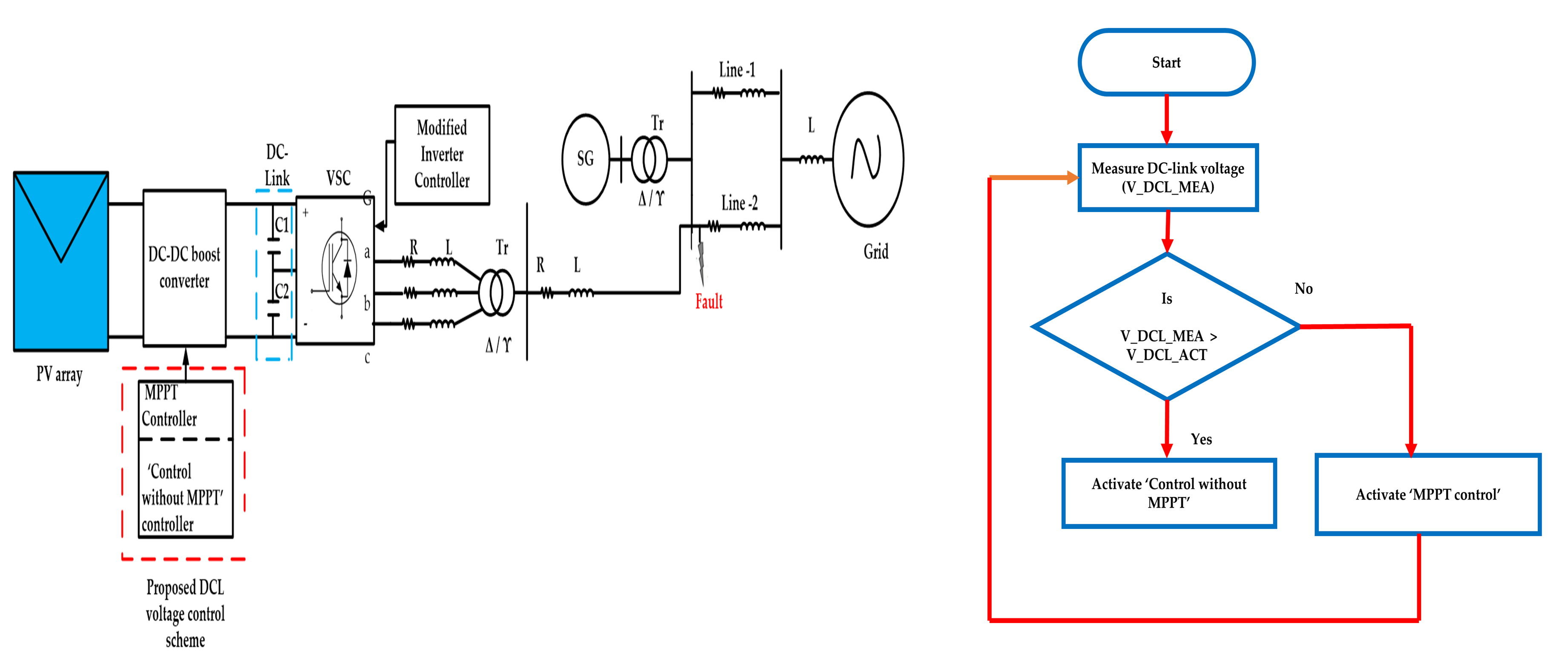
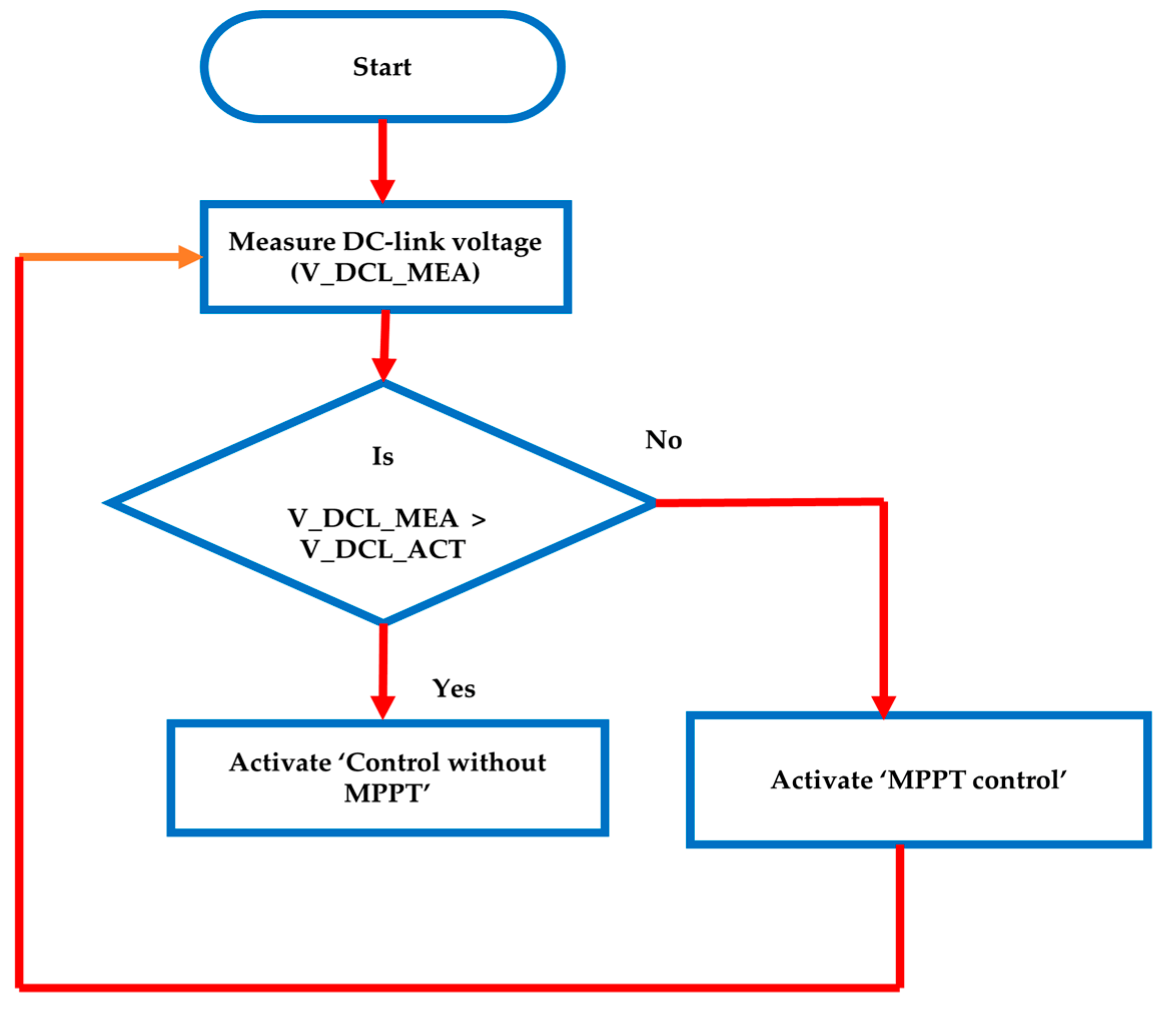
4.1. DC-Link (DCL) Voltage Control Scheme

The proposed DCL control scheme is shown in Figure 4. During normal operating conditions, the incremental conductance (IC) MPPT method is applied to track the maximum power from the PV arrays. Under three-phase fault conditions, the inverter cannot inject the SPV system with the maximum power into the grid owing to the sudden voltage sag. The surplus energy causes a sharp increase in the DCL voltage, which will damage the inverter module and the DCL capacitor. Hence, the “control without MPPT” controller is proposed during the fault period to reduce DCL over-voltage. The PV system should instantly change the “control without MPPT” operation mode when voltage sag appears in the PCC. Thus, a quick voltage-sag monitoring method is essential for FRT voltage control. In this study, the simple root-mean-square (RMS) detection method is adapted to identify the grid fault. The proposed method calculates the grid voltage RMS value of the phase-locked loop (PLL) by using Equation (9) to signal the control system that it should switch to operating under the fault-operation mode.
v sag   = v d 2   +   v q 2
where Vsag is the voltage sag, Vd is the d-axis component voltage, and Vq is the q-axis component voltage.
The “control without MPPT” controller is designed using the PI controller, with an anti-windup mechanism to avoid the saturation of the integral gain (Ki). The output of the controller is the duty cycle (d2), which is calculated using Equation (10):
d 2   = ( K p +   K i T s   Z Z 1 )   ( V DCL _ ref     V DCL _ meas ) .
where d2 is the duty cycle, KP is the proportional gain, Ki is the integral gain, Ts is the sample time, VDCL_ref is the reference DC voltage, and VDCL_meas is the measured DC voltage. The modified integrator gain is:
Ki modified = K i + K aw   ( d sat     d unsat )
The saturated control signal is calculated as follows:
d sat   = min ( max ( d unsat , d min ) ,   d max )
where, Kaw is the anti-windup gain, dunsat is the unsaturated duty cycle, dmin is the lower limit for the duty cycle, and dmax is the maximum limit for the duty cycle.
The simple PI controller selected for this study provides immediate changes in the control signal according to the respective set value. The proposed control strategy controls the injected active power into the grid during voltage sag, while avoiding over-voltage in the DCL. When we use the PI controller under the “control without MPPT” mode, a problem may occur because the system works at a different point than the MPP under fault conditions. Therefore, the DCL voltage takes a long time to reach the nominal value after the fault is cleared, because the error in the DCL voltage promotes the accumulation of control action in an integral part of the PI controller at the end of voltage sag, which should be compensated for by an input error in the opposite direction. Therefore, the actual DCL voltage is reduced below the reference value, which may cause the inverter to lose control and be disconnected. To solve this issue, the anti-wind-up technique is applied to the PI controller to accumulate excessive control action when it exceeds a specified value. Thus, when the voltage sag ends, the DCL voltage recovers to the nominal value without perceptible overcompensation.
The operational flowchart is shown in Figure 5. Under fault conditions, initially the DC-link voltage is measured and compared with a actual DCL voltage. If it exceeds the actual value, the “control without MPPT” mode is enabled; otherwise, the MPPT control is enabled. The “control without MPPT” controller is enabled in the system until the DCL voltage is equal to the actual DCL voltage.

4.2. Reactive Power Injection Scheme

For the grid-connected operation, the real power is regulated using id, and the reactive power is regulated using iq. The equations of the grid inverter can be given in d-q frame rotating at the line frequency, as follows:
di d dt =   R L i d   +   v d L     v gd L   +   ω i q
di q dt   =   R L i q +   v q L     v gq L   +   ω i d
where id and vd are the d-axis components of the inverter current and voltage, iq and vq are the q-axis components of the inverter current and voltage, and vgd and vgq are the d-axis and q-axis components of the grid voltage. When controlling P and Q independently, the d-axis reference voltage (vd-ref) and q-axis reference voltage (vq_ref) will be obtained. They are converted into the stationary reference frame using the dq-abc transformation, and sinusoidal pulse width modulation (SPWM) signals are then generated accordingly. To provide the reactive power support to the grid under fault conditions, this work proposes a modified control system for the voltage source converter (VSC), as shown in Figure 6. During normal operating conditions, the inverter control system generates a d-axis reference current to maintain the DCL voltage by using an external voltage regulator, and maintaining the unity power factor. The d-axis reference current controller, designed with the back-calculation anti-windup method, is used to avoid the error accumulation of the integral part under fault conditions. The quadrature axis reference current (Iq_ref) is fixed to zero to keep the unity power factor under normal conditions.
The PLL measures the system frequency, and provides the phase synchronous angle for the dq transformation block. When voltage sag is created on the grid, the reactive current injection level is calculated based on Equation (7). During the occurrence of voltage sag on the grid point (PCC), the inverter active power injection control mode is changed to the reactive-power injection control mode. At that time, the PI controller controls the q-axis reference current (Iq_ref). Under fault conditions, the difference between the actual grid voltage (Vgrid_actual) and the measured grid voltage (Vgrid_meas) is used to calculate the required amount of reactive power (Q) needed for the grid by using Equation (15), and Iq_ref is calculated using Equation (16):
Q = ( k p + k i S )   ( V grid _ actual     V grid _ meas )
Iq _ ref = ( 2 S ) / ( 3 V grid )
I qmax = ( 2 Q ) / ( 3 V grid )
where S is the apparent power, and the current Iq_ref is limited based on the inverter current rating. Therefore, the range of the active power (P) during fault conditions is given by:
0     P   S 2 Q 2
The reactive power capacity of the inverter can be utilized to compensate for the voltage sag under fault conditions. The maximum range of the inverter reactive power injection capacity is determined as follows:
Q max = S max 2     P spv 2
where Smax is the maximum apparent power, and Pspv is the PV power.
The proposed scheme, based on reactive power injection, is presented in Algorithm 1. The algorithm first checks the phase fault conditions individually, based on the RMS value of the voltage value. When the PCC voltage drops below 0.9 p.u, the SPV system injects the active power (P) and reactive power equal capacity. If the PCC voltage lies between 0.5 and 0.9 pu, the active power is fixed to the nominal value, and the reactive power during LVRT is represented in Q_LVRT. Otherwise, if the voltage is below 0.5 pu, the active power is disabled and the whole capacity of the inverter is used to inject the maximum reactive power (Qmax) into the grid to boost the PCC voltage.
Algorithm 1: Proposed LVRT method based on reactive power injection.
1: Measuring Vg_rms value in per unit (pu);
2: Nominal Vg_rms = = 1.01;
3: If (Vg_rms < 0.9)
4:   P = = P*  &&  Q = = Q*;   % P* and Q* are the post-fault active and reactive powers
5: else if (0.5 < Vg_rms < 0.9)
6:   P = = P*  &&  Q = Q_LVRT;   % P is the pre-fault active power and Q_LVRT is the Q at LVRT
7: else if (Vg_rms < 0.5)
8:   P = = 0  &&  Q = = Q max;   % Q max is the maximum reactive power injection into the grid
9: else
detecting Vg-rms value in per unit (pu);
10: return to step 3

5. Simulation Result Analysis and Discussion

5.1. Simulation Details

The given power system model (Figure 7) is simulated using MATLAB/Simulink software to evaluate the performance of the proposed control scheme. The PV array is used to deliver the maximum value of 100 kW at 1000 W/m2 irradiance; a boost converter is used to increase the PV voltage to 500 V DC; the I-V and P-V characteristics of SPV system are shown in Figure 8; the switching duty cycle is optimized by the MPPT controller under normal conditions; and the VSC converts 500 V DC to 260 V alternating current (AC) and retains the unity power factor, and is connected with the single machine-infinite bus (SMIB) system via step-up transformer. To validate the performance of the proposed LVRT control scheme for the grid connected PV system, the German E.ON grid code (GCC), shown in Figure 3, is taken as a reference.

5.2. Simulation Results

The LVRT performance of the system with the proposed control scheme is demonstrated under both symmetrical and asymmetrical fault conditions. To capture all the possible details, and for better representation, a uniform time span of 0–5 s used in the graph results. A zoomed-in portion is also provided inside all figures for better visualization. The simulation results are described in the subsequent sections.

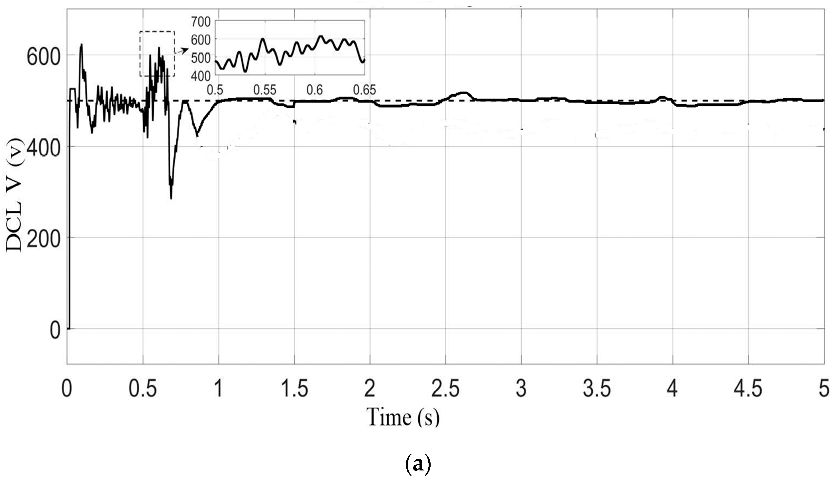
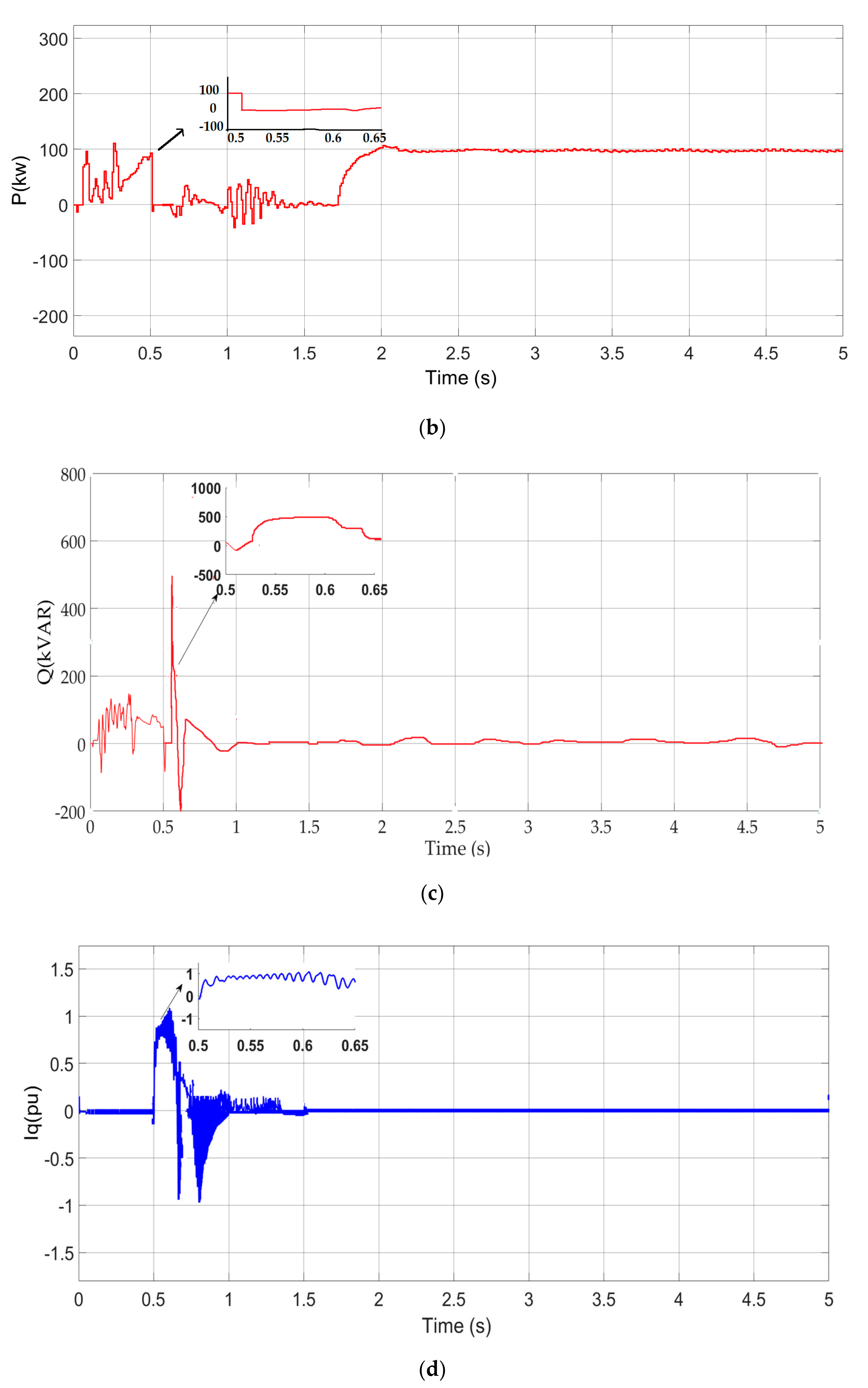
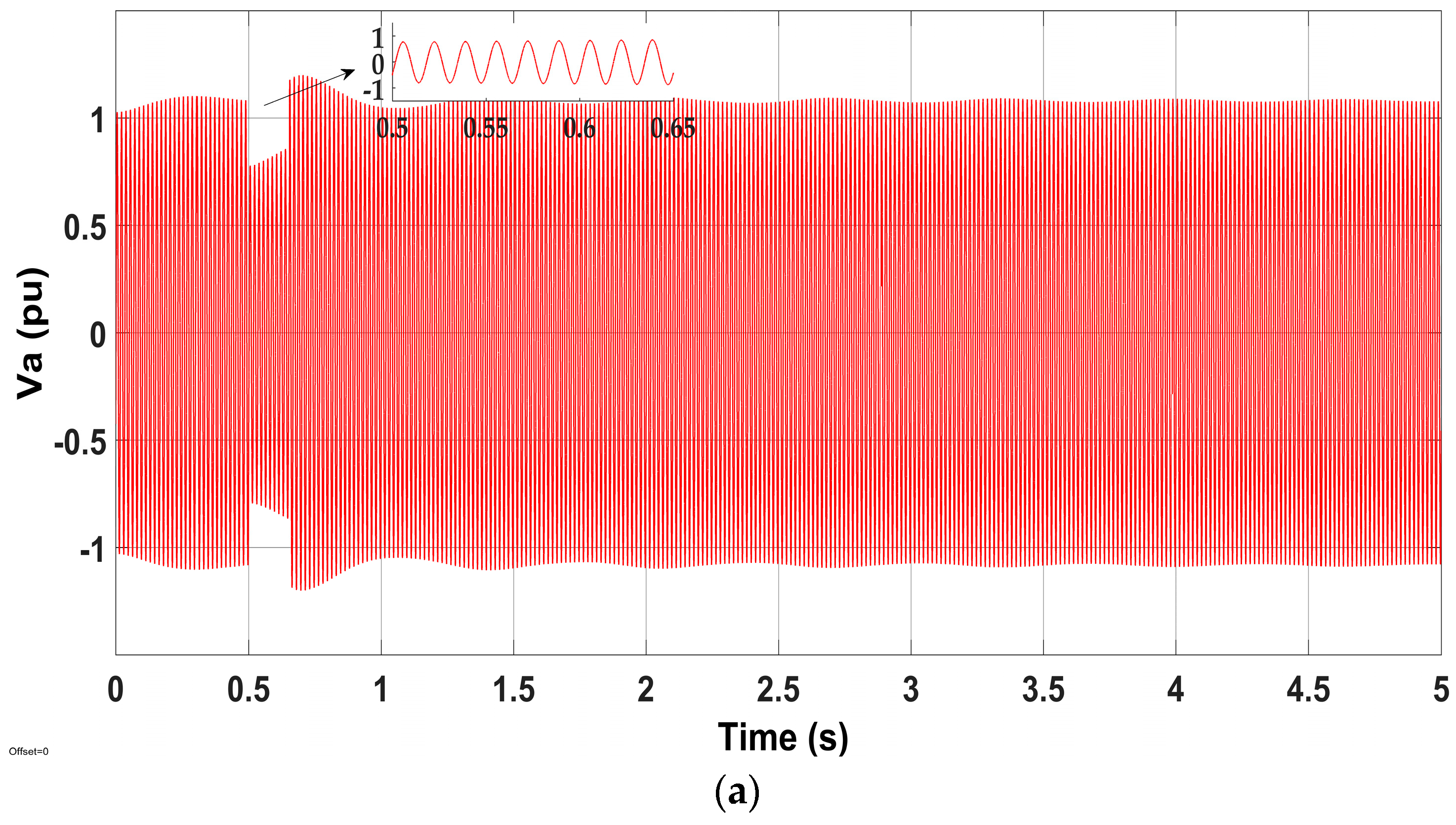
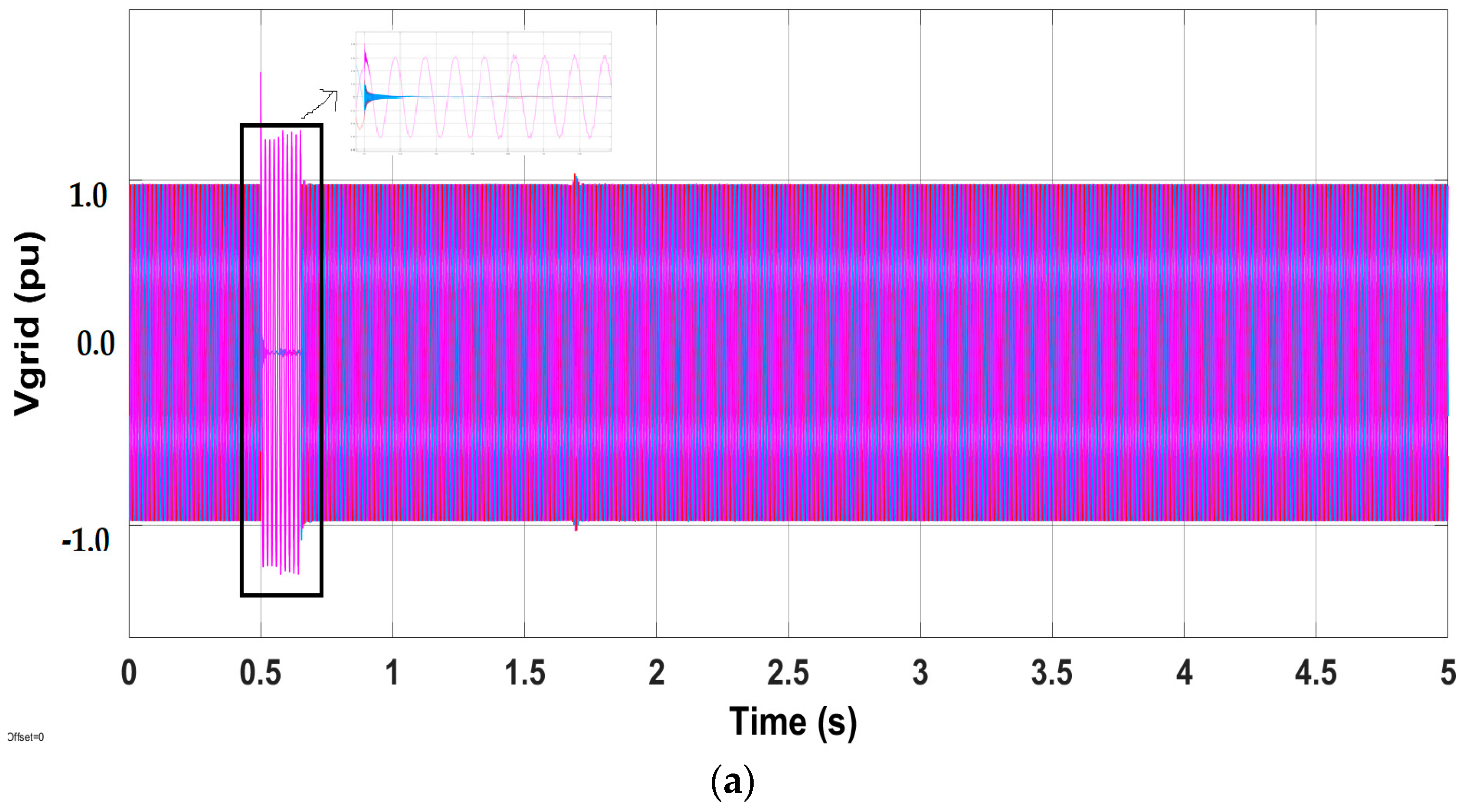
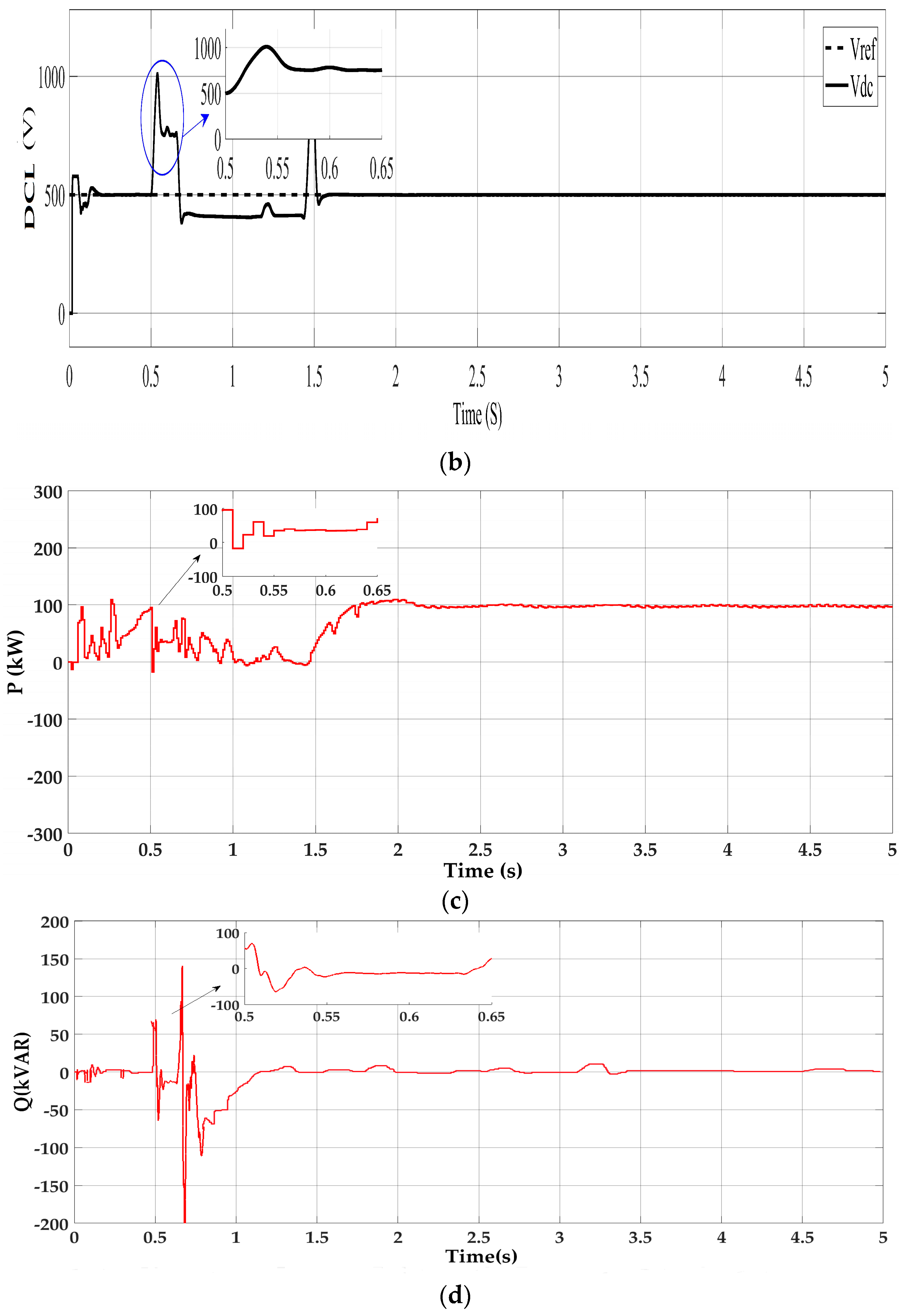
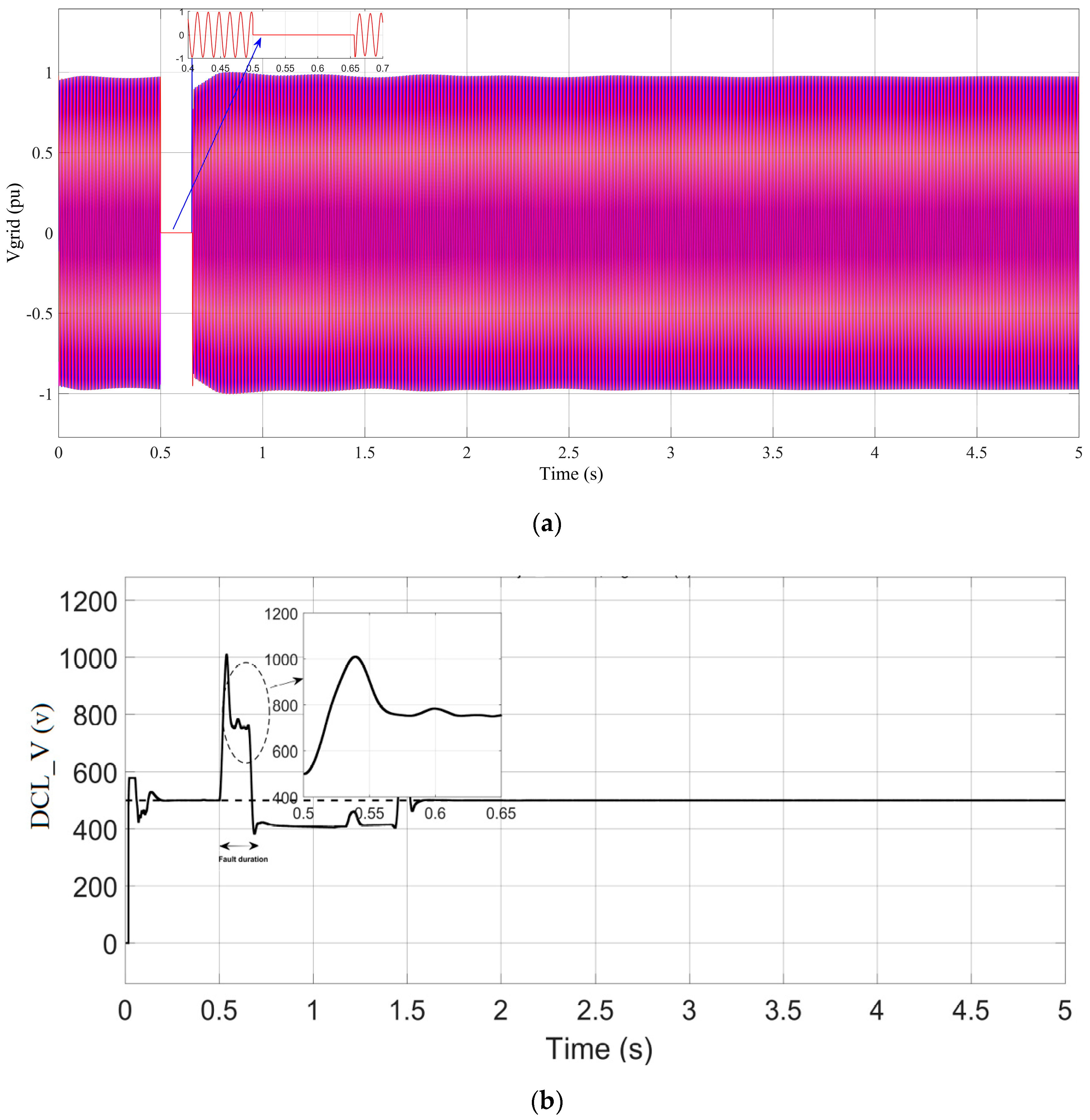
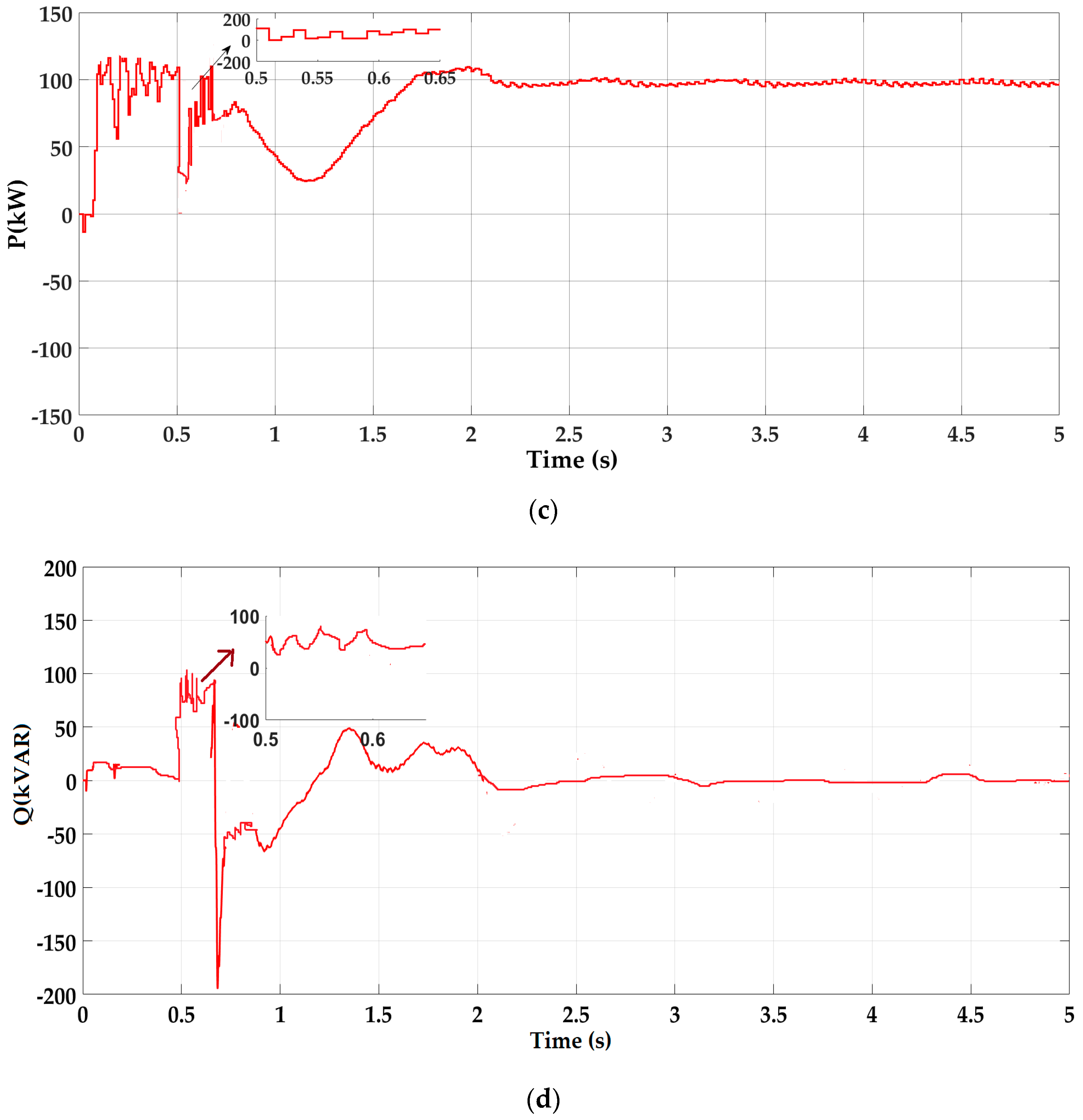
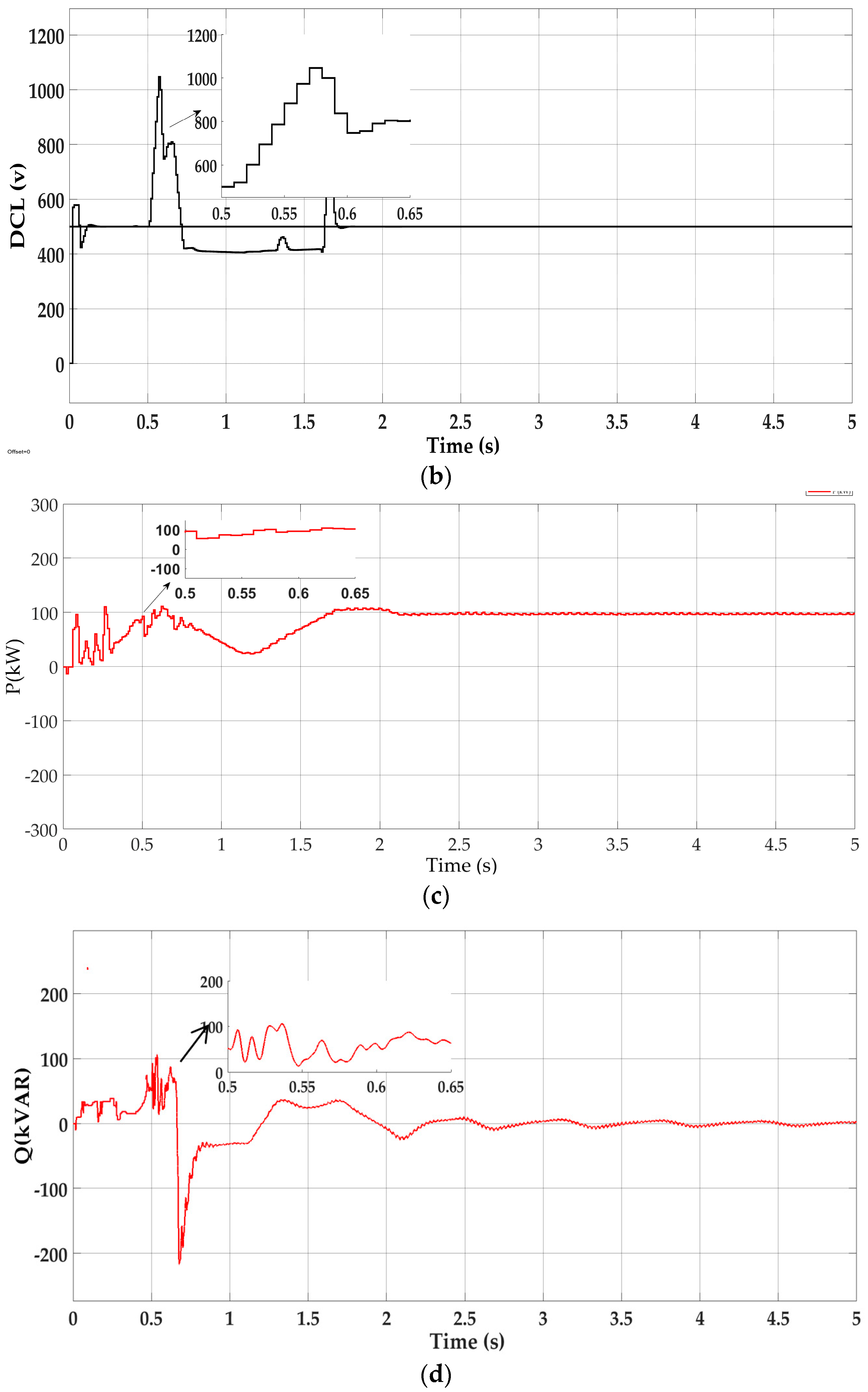
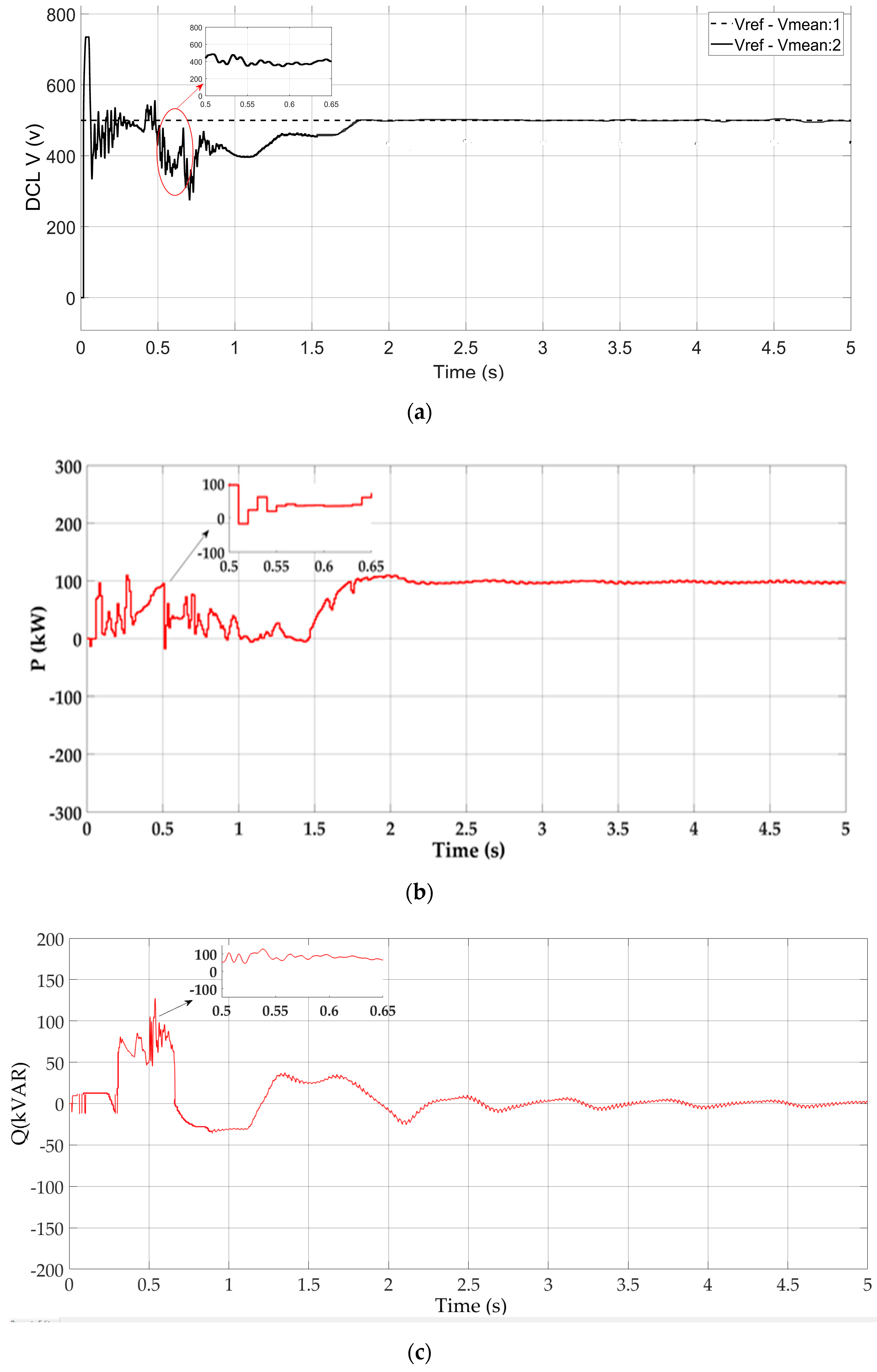
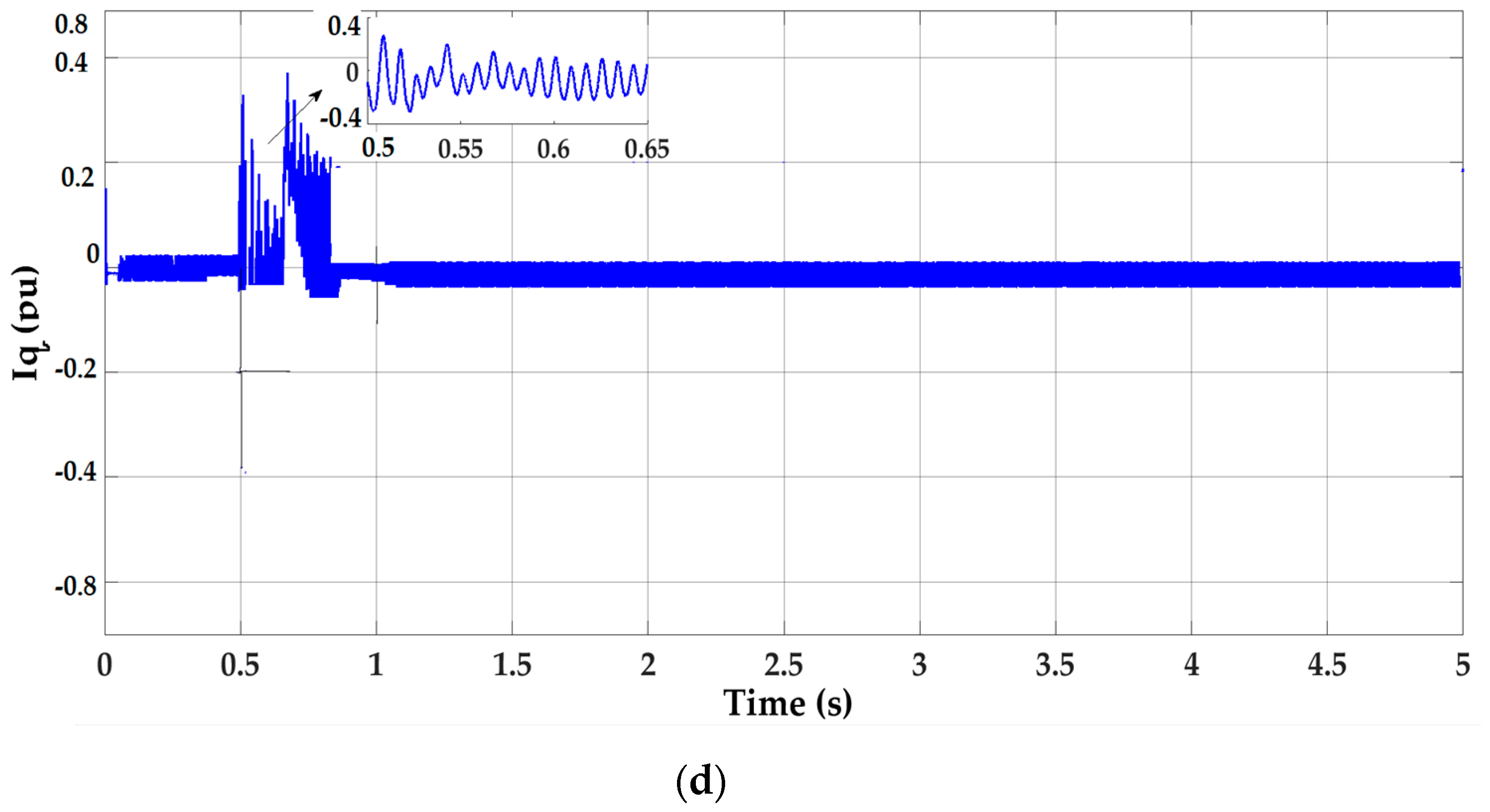
LVRT Enhancement by the Proposed Control Scheme under a Symmetrical Fault (3LG)

The effectiveness of the proposed control scheme in LVRT capability enhancement is investigated by applying a symmetrical fault (3LG) at line 2, near the PCC point (Figure 7). The fault is created at t = 0.5 s and cleared after 0.15 s. The simulation time is 5 s, and the mode is discreet with a step time of 50 μs. In this work, to verify the performance of the proposed control during the change in atmospheric conditions, irradiation and temperature varies from 250 w/m2 to 1000 w/m2 and 25 °C to 50 °C, respectively. Such parameter checks are another salient feature of this work, since most of the existing LVRT techniques require a constant irradiance and ambient temperature. The simulation results of the grid-connected SPV system without the proposed strategy (MPPT control) are shown in Figure 9. Figure 9a shows that, during the 3LG fault, 100% voltage sag occurs on the PCC without the proposed control scheme. This fault type, as the worst one, causes a severe voltage sag in the PCC. Once the 3LG fault occurs, the voltage at the PCC drops to zero. The DCL voltage is unstable with 1000 V overvoltage, which exceeds the limitation severely, as shown in Figure 9b. The IGBTs in the power converters may fail in this situation, and the SPV system cannot perform LVRT. It can be seen in Figure 9c that the SPV system injects maximum active power at the same time that it injects less reactive power (Figure 9d),which is not acceptable under a 3LG fault.
The simulation results with the proposed control strategy are shown in Figure 10. As shown in Figure 10a, DCL voltage retains the maximum 600 V, which is below the DCL over-voltage limitation. Simultaneously, as shown in Figure 10b, the SPV system can inject an average amount of 500 kVAR reactive power (Qmax) into the grid to support grid recovery under 100% voltage sag conditions (Figure 10b). The SPV output active power (Figure 10c) is effectively reduced to zero, as mentioned in Algorithm 1, which enhances the LVRT capability of the system. Figure 10d shows that the PV inverter injects 1.01 pu reactive current (Iq) under 100% voltage sag, which meets the German E.ON grid code requirements. Since the input parameters of irradiance and temperature vary, the active and reactive power results show trivial oscillations in the pre-fault period. However, active and reactive power results in the post fault conditions reaching the steady state within the time limit mentioned in the E.ON grid code.
The reliability of the above results when compared with previous studies can be clearly seen by considering the results in [31]. These results address the excessive AC current and DC voltage using similar means to this study, but using different controls and additional devices, which increases the cost.

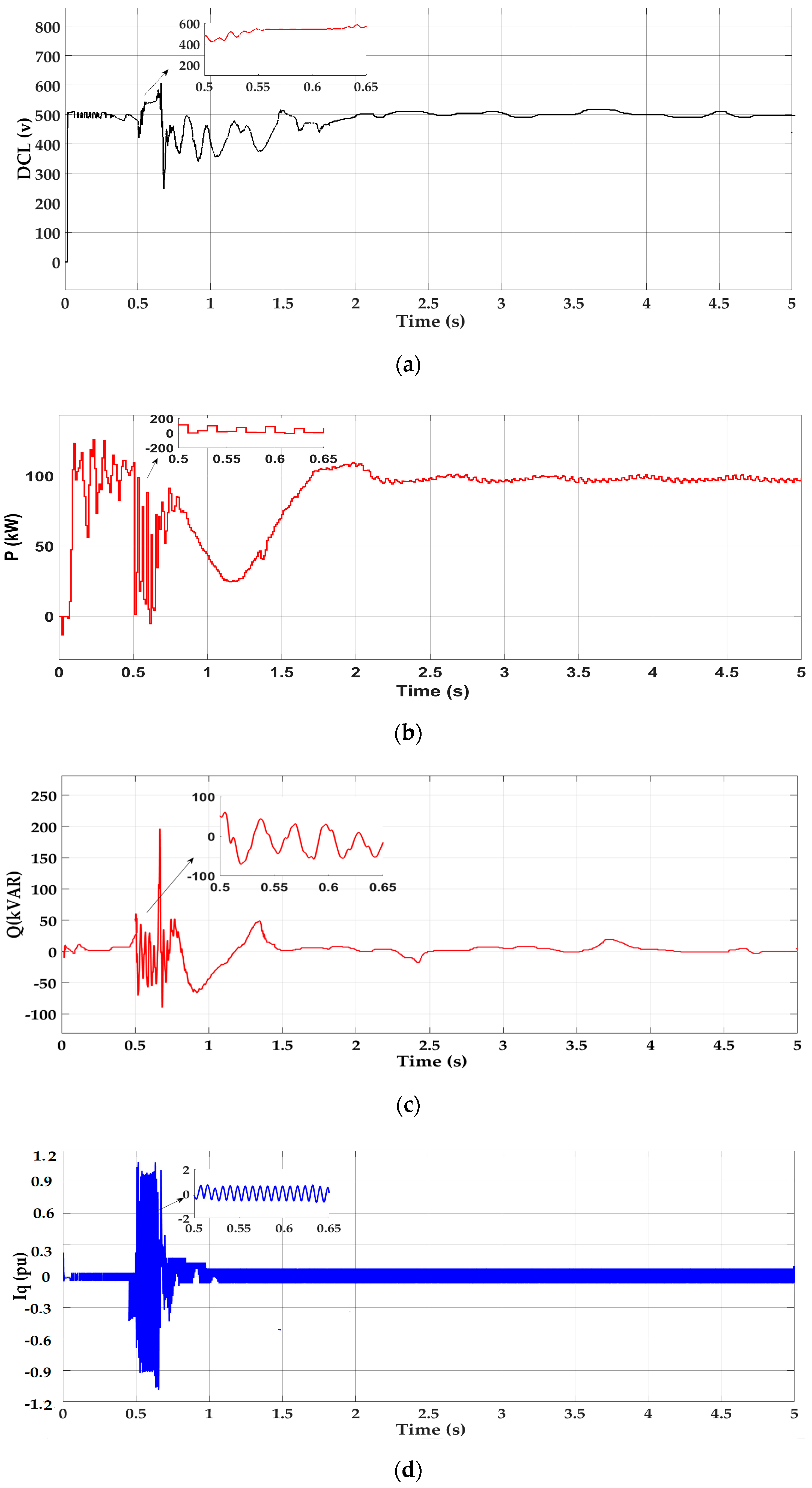
5.3. LVRT Enhancement by the Proposed Control Scheme under an Asymmetrical Fault

In this section, the proposed control strategy is verified under two different types of asymmetrical faults—single-line to ground fault (1LG) and two-line to ground fault (2LG).

5.3.1. Single-Line to Ground Fault (1LG)

In this section, the effectiveness of the proposed control scheme is tested and compared with and without the proposed control (MPPT control) scheme under asymmetrical fault conditions. For this purpose, a single-line to ground (1LG) fault (phase A to ground) is applied in line 2 in Figure 7, at t = 0.5 s for 150 ms. The simulation results of the grid-connected SPV system without the proposed control scheme are shown in Figure 11. Observations from the grid voltage (phase ‘a’) profile Va in Figure 11a indicate that the voltage amplitude drops to Va = 0.71 pu from its nominal value Va = 1.01 pu, corresponding to a voltage sag of 70%. The DCL voltage is unstable with 1050 V over-voltage, which seriously exceeds the DCL over-voltage limitation, as shown in Figure 11b. The SPV system injects an average amount of 80 kW (i.e., 80% of the SPV rated power capacity) into the grid, which means the MPPT control scheme does not effectively reduce the output active power during the fault, as is demonstrated in Figure 11c, so that the SPV inverter experiences an over-current. This case inverter can be disconnected from the grid, which is a negative sign of LVRT enhancement.
The simulation results of the grid-connected SPV system with the proposed control scheme are shown in Figure 12. As shown in Figure 12a, DCL voltage maintains the maximum value of 580 V with few fluctuations. It is worth pointing out that, when the voltage sag occurs, the DC side input current may not be equal to the output current, leading to flucation of the DCL voltage. Figure 12b shows that, with the proposed control scheme, the SPV system delivers less active power than the MPPT control scheme during the fault. The reason is that with the proposed control scheme the SPV system supplies the grid with reactive current as required in the GC (Figure 12d). This will reduce the active power flowing through the inverter to the grid. Hence, the SPV inverter will not experience any over-current, which is a positive sign of LVRT enhancement. Furthermore, the SPV system is injecting the required amount of reactive power according to the GC into the grid for voltage recovery (Figure 12c), and after the fault is cleared, the system goes back to its normal mode within the time limit mentioned in the GC.

5.3.2. Two-Line to Ground Fault (2LG)

The simulation results of the grid-connected SPV system with MPPT control are shown in Figure 13. Figure 13a shows the response of the MPPT control scheme when an asymmetrical two-line to ground (2LG) fault (Phases ‘a’, ‘b’ to ground) occurs, with the voltage dropping to 0.21 pu from its nominal value (1.01 pu) for 150 ms, and therefore with voltage sag of around 20%. Figure 13b shows that the DCL voltage rises sharply to 1100 V, which trips the over-voltage protection circuitry. During a 2LG fault, the active power can be delivered to the grid by the healthy phase, unlike during a 3LG fault where no active power is injected into the grid. However, Figure 13c shows that the SPV system injects an average amount of 60 kW (i.e., 60% of the SPV rated power capacity) active power into the grid, which is not adequate under an unbalanced grid fault, since the grid point (PCC) voltage level is low. In this case, the inverter is overloaded (i.e., over-current). Figure 13d depicts that the SPV system injects less reactive power into the grid, which is not enough to support voltage recovery. Figure 14 shows the response of the proposed control scheme. DCL voltage is maintained at the maximum of 600 V, which has little oscillation, as shown in Figure 14a. Figure 14b illustrates that the SPV system output of active power has been effectively reduced to a null, and because of this the SPV inverter will not experience any severe over-current issues. At the same time, the SPV system injects an average amount of 200 kVAR of reactive power into the grid according to the GC in order to support voltage recovery, as shown in Figure 14c. In this case, the standard requires to provide 100% reactive current into the grid, it is shown in Figure 14d.

5.4. Quantification of Results

In addition to graphical representations to provide a clearer view, the LVRT has been evaluated using several performance indices, such as the PV active power deviation and DCL voltage deviations. A lower value of the indices indicates an enhanced system performance [32]. The performance indices are calculated using Equations (20)–(21):
DCL vol =   0 T | Δ V dc |   dt V dc _ rated
PV power =   0 T | Δ Ppv |   dt P pv _ rated
where Δ V dc and Δ Ppv stand for the deviation of the DC-link voltage and PV array power. The period of interest is from 0 s to T = 5 s. The performance comparison of various control techniques is given in Table 1. It is clear from Table 1 that the improvement is significant when using the proposed control scheme, since it provides the lowest index values. Hence, the proposed control scheme is better than the no control (MPPT) scheme to enhance the LVRT of the system, under both symmetrical and asymmetrical faults.

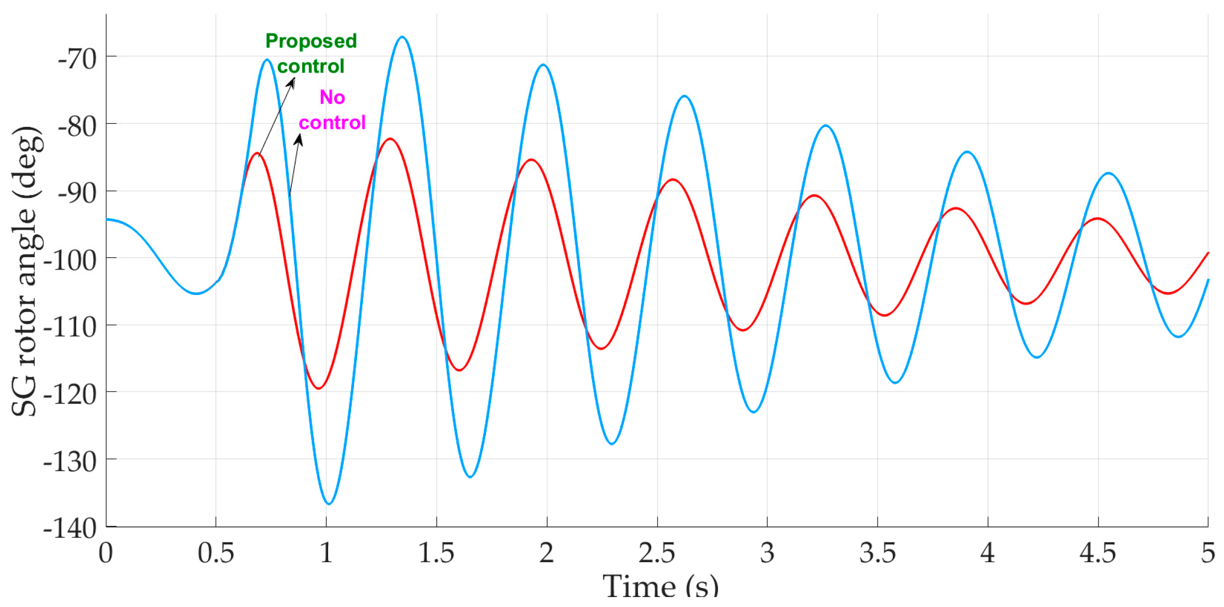
5.5. Stability Analysis

Stability analysis, regarding both symmetrical and asymmetrical fault conditions, was undertaken with the proposed control scheme. The LVRT capability of the SPV system has a positive effect on the transient stability of power systems, since the disconnection of a large amount of SPVs would stress the power system even more. The performance of the proposed control scheme is examined when the test system (Figure 7) is subjected to a three-phase short-circuit fault (3LG). The fault is considered to occur at 0.5 s, and is cleared after 150 ms. Figure 15 illustrates the rotor speed of the synchronous generator (SG) during fault conditions, with and without the proposed control embedded with the SPV grid-connected system. The simulation results clearly show synchronous generator (SG) speed oscillations (Figure 15) over a wide range of 1.0 pu to 1.012 pu, with no control during the fault. However, the SG speed oscillation is significantly reduced with the proposed control, which is a positive indicator of the increased transient stability margin of the power system. The rotor-angle variation of the SG connected with the SPV system, with and without the proposed control, is shown in Figure 16. The results show that the system does not lose its rigidity, and remains robust to the faults. The simulation results illustrate that, with the proposed control system, the peak rotor angle of the synchronous machine is significantly reduced, leading to a much longer critical clearing time (CCT) and a positive impact of the stability enhancement of the system. For a clearer perspective, the stability of the system was evaluated using several performance indices, such as the speed deviation of the SG and the rotor angle deviation of the SG. A lower value of the indices indicates an enhanced system performance. Mathematical representations of the performance indices of the SG can be defined as follows:
SG speed =   0 T | Δ ω |   dt ω SG _ rated
SG angle = 0 T | Δ δ |   dt δ SG _ rated
It is evident from Table 2 that the system performance on stability is weak without the proposed control scheme. Notable improvement is observed with the proposed control scheme. The consistency of the above results with other previous studies can be clearly seen when comparing with the work in [32]. Similar results were achieved in this work; however, a parallel-resonance bridge-type fault current limiter (PRBFCL) was used, and additional hardware devices increase the cost of the system. Alternatively, the proposed control scheme obtains these better results with lower costs.

6. Comparison of the Conventional and Proposed LVRT Strategies

Figure 17 shows the schematic diagram for the DC breaking chopper implemented in the conventional scheme. When voltage sag occurs on the grid and the DCL voltage rises, the DC breaking chopper is enabled by a switch, and thus the power from the DCL is dissipated into the chopper resistor. The simulation results of the grid-connected SPV system with chopper control are shown in Figure 18. Figure 9a and Figure 18a show that LVRT has been adapted, because both schemes provided approximately the same response; that is, the DCL over-voltage is maintained below the threshold value (25% of the rated voltage). Figure 9b and Figure 18b show the active power injected into the grid under fault conditions. The simulation results presented in Ntare, R et.al, [33] show the effectiveness of the DC-break circuit and current limiter strategies to enhance the LVRT capability, mitigate voltage sag by addressing excessive DC link voltage, and ride through the grid fault safely. However, this control scheme does not analyze the inverter reactive power support to the grid under fault conditions. Alternatively, the proposed control system provides the DCL over voltage protection reactive power support, and mitigates voltage sag. From a practical implementation point of view, the application of the DC-breaking chopper scheme increases the overall system cost and power loss during the duration of a fault. However, the proposed control scheme contains two controllers, of which the MPPT controller exists in all SPV systems; therefore, it is not included in the cost calculation for the proposed control. The only additional unit is “control without MPPT,”—a PI controller based-PWM generator, as well as the voltage sensors and switch. Therefore, the proposed control scheme costs a little more than the existing MPPT system. However, the PI controller can be developed by using a simple operational amplifier with resistors and capacitors. These are basic components, and are inexpensive and easily available. Thus, the proposed control system can be implemented with larger grid-connected SPV systems easily.

6.1. Limitations of the Proposed Control Scheme

The proposed control strategy has the following limitations:
The proposed control strategy is not appropriate for the single-phase two-stage PV system, since single-phase PV systems are commonly connected to low-voltage feeders, which are mainly resistive (i.e., with a high R/X ratio). Therefore, injecting reactive power into the grid under fault conditions may not contribute significantly to grid voltage recovery. Nevertheless, the main objective of the proposed control approach is to reduce the active power injection to the grid, and at the same time inject reactive power for voltage recovery during fault conditions.
Avoiding operation of the SPV generation system at MPPT during fault conditions reduces the efficiency of the system. However, this would help in reducing the size of the capacitor connected to the DC-link. In addition, the network faults are for very shorter periods of time, which will not affect the system performance much.
The control requires an additional stage of computation, which may increase the cost a little, but the main advantage is avoiding DC link over-voltage, which eventually saves the capacitor from being damaged.

7. Conclusions

This work has proposed a novel LVRT control strategy for the two-stage three-phase SPV system, to ensure a satisfactory operation during grid fault conditions. A DCL voltage control scheme using MPPT and a “control without MPPT” controller has been proposed and analyzed using simulations, under symmetrical and asymmetrical fault conditions. The simulation results show that the proposed scheme can effectively protect the system against DCL over-voltage occurances under any fault conditions. For the benefit of numerical quantification of the system performance, some indices have been calculated and indeed support the graphical representation of the simulation results. The proposed algorithms support seamless operation mode transitions, besides they support reactive power injection according to the grid codes (GCs). The advantages of the proposed scheme are that it does not interfere with normal operation conditions and, as a result, it is always active. Furthermore, the method does not lead to instability during the most critical time, when the fault occurs and is cleared, as may occur when other methods are used. Moreover, in the proposed control scheme, there is no component to calculate the amount of excess power to be removed, and it uses only the DCL voltage to determine the mode change from the MPPT control scheme to the proposed control scheme, which makes it simple and easy to implement with the existing controllers. Compared with the previous LVRT schemes, the proposed scheme requires only a PI based DCL voltage regulator and mode-changing relay. Regarding the outer loop in the VSC control which carries out the function of the DCL voltage regulator, only a mode changing circuit is required for the proposed control, which reduces the practical implementation difficulties. Therefore, the proposed LVRT control strategy can be extensively applied to grid connected two-stage solar PV systems.
Investigation of the usefulness of the proposed control scheme in a large distribution network will be undertaken in future research.

Author Contributions

Conceptualization, S.R.M., P.A.J., and D.D.; methodology, S.R.M., P.A.J., and D.D.; software, S.R.M.; validation, D.D. and P.A.J.; formal analysis, S.R.M. and P.A.J.; Investigation, S.R.M., and D.D.; resources, S.R.M. and A.A.; writing—original draft preparation; S.R.M., P.A.J., and D.D.; review and editing; S.R.M., D.D., P.A.J.,and M.H.S.; supervision, P.A.J. and D.D.; funding acquisition, S.R.M. and A.A.

Funding

This work is funded by Deanship of Scientific Research at King Faisal University, grant number 186092.

Acknowledgments

The authors express appreciation to the Deanship of Scientific Research, King Faisal University administration for continued research support.

Conflicts of Interest

The authors declare no conflict of interest.

Nomenclature

PspvPhotovoltaic Array Power (W)PgfGrid Power -Fault Condition (pu)
∆TFault Period (s)INNominal Current (pu)
PDC-linkDC-Link Power (W)VDCLDC-Link Voltage (v)
CDCDC-Link Capacitor (F)KpProportional Gain
PgGrid Power (pu)VDCL_fDC-Link Voltage-Fault Condition (v)
IqReactive Current(pu)KiIntegral Gain
VgrmsGrid Voltage RMS value (pu)KawAnti-Windup Gain
IgrmsGrid Current in RMS value (pu)QReactive Power (kVAR)
IgrmsGrid Current in RMS value (pu)PActive Power (kW)
Iq0Initial Reactive Current (pu)SApparent Power (w)
IgGrid Current (pu)QmaxMaximum Reactive Power (pu)
CDCDC-Link Capacitor (F)TsSample Time (s)
DDuty Cycled2Duty Cycle for the Proposed Control
Vd_refd-Axis Reference Voltage (pu)dminLower Limit for the Duty Cycle
Vq_refq-Axis Reference Voltage (pu)dmaxMaximum Limit for the Duty Cycle
Id_refd-Axis Reference Current (pu)dunstaUnsaturated Limit for the Duty Cycle
Iq_refq-Axis Reference Current (pu)dsatSaturated Limit for the Duty Cyle
∆VdcDC-Link Voltage Deviation (v)SGspeedSynchronous Generator Speed (pu)
∆PpvPV-Power Deviation (w)SGangleSynchronus Generator Rotor Angle (deg)
Ppv-ratedRated PV Power (w)ωSGratedRated Synchronous Generator Speed (pu)
Id d-Axis Current (pu)δSG_ratedRated Synchronous Rotor Angle
SmaxMaximum Apparent Power (w)

References

  1. Messenger, R.; Ventre, J. Photovoltaic Systems Engineering, 3rd ed.; CRC Press: Boca Raton, FL, USA, 2010. [Google Scholar]
  2. Miret, J.; Castilla, M.; Camacho, A.; de Vicuña, L.G.; Matas, J. Control scheme for photovoltaic three-phase inverters to minimize peak currents during unbalanced grid-voltage sags. IEEE Trans. Power Electron. 2012, 27, 4262–4271. [Google Scholar] [CrossRef]
  3. Yang, Y.; Blaabjerg, F.; Zou, Z. Benchmarking of grid fault modes in single-phase grid-connected photovoltaic systems. IEEE Trans. Ind. Appl. 2013, 49, 2167–2176. [Google Scholar] [CrossRef]
  4. Marinopoulos, A.; Papandrea, F.; Reza, M.; Norrga, S.; Spertino, F.; Napoli, R. Grid integration aspects of large solar PV installations: LVRT capability and reactive power/voltage support requirements. In Proceedings of the 2011 IEEE Trondheim PowerTech, Trondheim, Norway, 19–23 June 2011; pp. 1–8. [Google Scholar]
  5. Al-Shetwi, A.Q.; Sujod, M.Z. Modeling and control of grid-connected photovoltaic power plant with fault ride-through capability. J. Sol. Energy Eng. 2017, 140, 021001. [Google Scholar] [CrossRef]
  6. Manikanta, B.V.V.N.; Kesavarao, G.; Shefali, T. LVRT of grid -connected PV system with energy storage. Int. J. Control Theory Appl. 2017, 10, 75–86. [Google Scholar]
  7. Hossain, M.K.; Ali, M.H. Low voltage ride through capability enhancement of grid connected PV system by SDBR. In Proceedings of the IEEE PES T&D Conference and Exposition, Chicago, IL, USA, 14–16 April 2004; pp. 1–5. [Google Scholar]
  8. Sabir, A. A novel low-voltage ride-through capable energy management scheme for a grid-connected hybrid photovoltaic-fuel cell power source. Int. Trans. Electr. Energy Syst. 2018, e2713. [Google Scholar] [CrossRef]
  9. Yang, W.; Deng, C.; Zheng, F. Low voltage ride-through capability improvement of photovoltaic systems using a novel hybrid control. J. Renew. Sustain. Energy 2017, 9, 055301. [Google Scholar] [CrossRef]
  10. Ou, T.C.; Lu, K.H.; Huang, C.J. Improvement of transient stability in a hybrid power multi-system using a designed NIDC (Novel Intelligent Damping Controller). Energies 2017, 10, 488. [Google Scholar] [CrossRef]
  11. Wu, Y.-S.; Chang, C.-H.; Chen, Y.-M.; Cheng, C.-S.; Liu, C.-W.; Chang, Y.-R. The current control of PV inverter for low voltage ride through. In Proceedings of the 15th International Power Electronics and Motion Control Conference, Novi Sad, Serbia, 4–6 September 2012; pp. LS1d.4-1–LS1d.4-6. [Google Scholar]
  12. Bae, Y.; Vu, T.K.; Kim, R.Y. Implemental control strategy for grid stabilization of grid-connected PV system based on German grid code in symmetrical low-to-medium voltage network. IEEE Trans. Energy Convers. 2013, 28, 619–631. [Google Scholar] [CrossRef]
  13. Yang, F.; Yang, L.; Ma, X. An advanced control strategy of PV system for low-voltage ride-through capability enhancement. Sol. Energy 2014, 109, 24–35. [Google Scholar] [CrossRef]
  14. Park, S.M.; Park, S.Y. Power weakening control of the photovoltaic-battery system for seamless energy transfer in micro grids. In Proceedings of the IEEE Applied power electronics Conference and exposition long beach, Long Beach, CA, USA, 17–21 March 2013; pp. 2971–2976. [Google Scholar]
  15. Nezhad, A.A.; Zaker, B.A.; Arani, A.K.; Gharehpetian, G.B. Impact of non-MPPT operation mode of PV system considering inverter fault current limiting. In Proceedings of the Conference on Electrical Power Distribution Networks Conference, Semnan, Iran, 19–20 April 2017; pp. 45–50. [Google Scholar]
  16. Bak, Y.; Lee, J.S.; Lee, K.B. Low-voltage ride-through control strategy for a grid-connected energy storage system. Appl. Sci. 2018, 8, 57. [Google Scholar] [CrossRef]
  17. Almeida, P.M.; Monteiro, K.M.; Barbosa, P.G.; Duarte, J.L.; Ribeiro, P.F. Improvement of PV grid-tied inverters operation under asymmetrical fault conditions. Solar Energy 2016, 133, 363–371. [Google Scholar] [CrossRef]
  18. Hong, C.M.; Ou, T.C.; Lu, K.H. Development of intelligent MPPT (maximum power point tracking) control for a grid-connected hybrid power generation system. Energy 2013, 50, 270–279. [Google Scholar] [CrossRef]
  19. Ou, T.C.; Hong, C.M. Dynamic operation and control of micro grid hybrid power systems. Energy 2014, 66, 314–323. [Google Scholar] [CrossRef]
  20. Sadeghkhani, I.; Golshan, M.E.; Guerrero, J.M.; Mehrizi-Sani, A. A current limiting strategy to improve fault ride-through of inverter interfaced autonomous micro grids. IEEE Trans. Smart Grid 2017, 8, 2138–2148. [Google Scholar] [CrossRef]
  21. Perera, B.K.; Ciufo, P.; Perera, S. Point of common coupling voltage control of a grid-connected solar photovoltaic (PV) system. In Proceedings of the 39th Annual Conference of the IEEE Industrial Electronics Society, Vienna, Austria, 10–13 November 2013; pp. 7475–7480. [Google Scholar]
  22. Ou, T.C. A novel unsymmetrical faults analysis for microgrid distribution systems. Int. J. Electr. Power Energy Syst. 2012, 43, 1017–1024. [Google Scholar] [CrossRef]
  23. Ou, T.C. Ground fault current analysis with a direct building algorithm for microgrid distribution. Int. J. Electr. Power Energy Syst. 2013, 53, 867–875. [Google Scholar] [CrossRef]
  24. Boujelben, N.; Masmoudi, F.; Djemel, M.; Derbel, N. Design and comparison of quadratic boost and double cascade boost converters with boost converter. In Proceedings of the 2017 14th International Multi-Conference on Systems, Signals & Devices (SSD), Marrakech, Morocco, 28–31 March 2017; pp. 245–252. [Google Scholar]
  25. Mousavi, M.; Shabestari, P.M.; Mehrizi-Sani, A. Analysis and output voltage control of a high-efficiency converter for DC Micro grids. In Proceedings of the IECON-44th annual conference of the IEEE Industrial Electronics Society, Washington, DC, USA, 21–23 October 2018; pp. 1029–1034. [Google Scholar]
  26. Mousa, M.; Ahmed, M.; Orabi, M. A switched inductor multilevel boost converter. In Proceedings of the 2010 IEEE International Conference on Power and Energy, Kuala Lumpur, Malaysia, 29 November–1 December 2010; pp. 819–823. [Google Scholar]
  27. Mirhosseini, M.; Pou, J.; Agelidis, V.G. Single-and two-stage inverter-based grid-connected photovoltaic power plants with ride-through capability under grid faults. IEEE Trans. Sustain. Energy 2015, 6, 1150–1159. [Google Scholar] [CrossRef]
  28. Máthé, L.; Séra, D.; Kerekes, T. Three-phase photovoltaic systems: Structures, topologies, and control. In Renewable Energy Devices and Systems with Simulations in Matlab® and Ansys; CRC Press: Boca Raton, FL, USA, 2017; pp. 67–90. [Google Scholar]
  29. Hossain, M.K.; Ali, M.H. Transient stability augmentation of PV/DFIG/SG–based hybrid power system by the parallel-resonance bridge fault current limiter. Electr. Power Syst. Res. 2016, 130, 89–102. [Google Scholar] [CrossRef]
  30. E.ON-Netz. Grid Code. High and Extra High Voltage. April 2009. Available online: http://www.eon-netz.com/ (accessed on 1 February 2019).
  31. Islam, S.; Zeb, K.; Din, W.; Khan, I.; Ishfaq, M.; Busarello, T.; Kim, H. Design of a Proportional Resonant Controller with Resonant Harmonic Compensator and Fault Ride Trough Strategies for a Grid-Connected Photovoltaic System. Electronics 2018, 7, 451. [Google Scholar] [CrossRef]
  32. Shafiul Alam, M.; Abido, M.A. Fault ride-through capability enhancement of voltage source converter-high voltage direct current systems with bridge type fault current limiters. Energies 2017, 10, 1898. [Google Scholar] [CrossRef]
  33. Ntare, R.; Abbasy, N.H.; Youssef, K.H.M. Low Voltage Ride through Control Capability of a Large Grid Connected PV System Combining DC Chopper and Current Limiting Techniques. J. Power Energy Eng. 2019, 7, 62–79. [Google Scholar] [CrossRef]
Figure 1. Schematic diagram of the grid-connected photovoltaic (PV) system. VSC: voltage source converter; DCL: DC-link; MPPT: Maximum power point tracking.
Applsci 09 00952 g001
Figure 2. Direct current–direct current (DC–DC) boost converter circuit. MOSFET: metal-oxide-semiconductor field-effect transistor.
Applsci 09 00952 g002
Figure 3. E.ON Netz GmbH code: (a) low voltage ride-through (LVRT) waveform and (b) reactive current injection requirement.
Applsci 09 00952 g003
Figure 4. Proposed DC-link voltage control.
Applsci 09 00952 g004
Figure 5. Flowchart showing operations of the proposed DC-link control scheme.
Applsci 09 00952 g005
Figure 6. The proposed inverter control scheme of reactive power injection.
Applsci 09 00952 g006
Figure 7. Power system simulation model. SG: Synchronous generator.
Applsci 09 00952 g007
Figure 8. I-V and P-V characteristics of the solar Photovoltaic array model used in the simulation analysis.
Applsci 09 00952 g008
Figure 9. Simulation results of MPPT control under a symmetrical (3LG) fault. (a) Grid voltage (Vgrid), (b) DC-link voltage (DCL), (c) active power (P), (d) reactive power (Q).
Applsci 09 00952 g009aApplsci 09 00952 g009b
Figure 10. Simulation results of the proposed control under a symmetrical (3LG) fault. (a) DC-link voltage (DCL), (b) active power (P), (c) reactive power (Q), (d) reactive current (Iq).
Applsci 09 00952 g010aApplsci 09 00952 g010b
Figure 11. Simulation results of the MPPT control scheme under an asymmetrical fault (1LG). (a) Grid voltage at PCC, (b) DC-link voltage (DCL), (c) active power (P), (d) reactive power (Q).
Applsci 09 00952 g011aApplsci 09 00952 g011b
Figure 12. Simulation results of proposed control scheme under an asymmetrical fault (1LG). (a) DC-link voltage (DCL), (b) active power (P), (c) reactive power (Q), (d) reactive current (Iq).
Applsci 09 00952 g012aApplsci 09 00952 g012b
Figure 13. Simulation results of the MPPT control scheme under an asymmetrical fault (2-LG). (a) Grid voltage at PCC, (b) DC-link voltage (DCL), (c) active power (P), (d) reactive power (Q).
Applsci 09 00952 g013aApplsci 09 00952 g013b
Figure 14. Simulation results of the proposed control scheme under an asymmetrical fault (2-LG). (a) DC-link voltage (DCL), (b) active power (P), (c) reactive power (Q), (d) reactive current (Iq).
Applsci 09 00952 g014
Figure 15. Synchronous generator (SG) rotor speed: no control and proposed control.
Applsci 09 00952 g015
Figure 16. Synchronous generator (SG) rotor angle: no control (MPPT control) and proposed control.
Applsci 09 00952 g016
Figure 17. Solar PV system with DC-breaking chopper LVRT control scheme.
Applsci 09 00952 g017
Figure 18. Simulation results of the DC-breaking chopper control scheme. (a) DC-link voltage (DCL), (b) active power (P).
Applsci 09 00952 g018
Table 1. Performance index enhancement with the proposed control scheme for symmetrical and asymmetrical faults.
Index Parameters (%)Values of Indices
3-LG1-LG2-LG
Control TypeMPPT ControlProposed ControlMPPT ControlProposed ControlMPPT ControlProposed Control
DCL vol 5.43.73.21.96.23.5
PVpower 4.32.83.12.25.14.2
LG: Line to ground.
Table 2. Values of indices for performance comparison during a 3LG fault.
Index Parameters (%)Value of Indices
MPPT ControlProposed Control
SGangle 1.80500.9722
SG speed 0.05000.0300

