Article

Wet Snow Flashover Characteristics of 500-kV AC Insulator Strings with Different Arrangements

1
Engineering Laboratory of Power Equipment Reliability in Complicated Coastal Environment, Graduate School at Shenzhen, Tsinghua University, Shenzhen 518055, China
2
Electric Power Research Institute of State Grid Tianjin Electric Power Company, Tianjin 300000, China
3
Department of Applied Sciences, Université du Québec à Chicoutimi, Chicoutimi, QC G7H 2B1, Canada
*
Author to whom correspondence should be addressed.
Appl. Sci. 2019, 9(5), 930; https://doi.org/10.3390/app9050930
Submission received: 7 January 2019 / Revised: 26 February 2019 / Accepted: 26 February 2019 / Published: 5 March 2019
(This article belongs to the Section Energy Science and Technology)

Abstract

:

Featured Application

External insulation design in wet snow conditions.

Abstract

In order to study the wet snow flashover characteristics of 500-kV AC insulator strings under different arrangements, wet snow flashover tests were carried out in the large climate chamber of China Electric Power Research Institute (CEPRI). The wet snow flashover voltages were obtained by the even-rising method and the flashovers were filmed by a camera. The test results showed that the installation of an anti-icing shed of large diameter could increase the wet snow flashover voltage. The distance between the two insulators was a key parameter that influenced the discharge process and the flashover voltage. Under Λ-string arrangement, for common insulators, the flashover performance of iced insulators increased with the connection angle; for anti-icing insulators, the flashover performance increased at first and then decreased with the connection angle. In wet snow conditions, when the connection angle was at the commonly adopted angle of 60°, the flashover performance of the common insulators under the V-string and Λ-string arrangements was almost the same. For anti-icing insulators, however, the V-string arrangement was recommended according to the tests. The results obtained in this study can provide a reference for external insulation design in wet snow conditions.

Graphical Abstract

1. Introduction

In Winter 2015, the city of Tianjin, in northeast China, was struck by a heavy snowstorm which seriously affected the safe operation of its grid. During the snowstorm, the temperature fluctuated around the freezing point so that the snow melting and freezing processes developed alternately. Moreover, the wind direction and velocity, as well as other atmospheric parameters were all favorable to the formation of wet snow according to the meteorological data. The snow filled the gaps between the sheds of composite insulators and icicles formed on the edge of the sheds, thereby degrading the insulation strength. It led to multiple flashovers on the 500-kV transmission lines and caused significant economic losses. Therefore, it is of great significance to study wet snow flashover characteristics of insulators and propose solutions to minimize the flashover incidents.
Snow can be divided into two categories, wet snow and dry snow, by the process of its formation [1,2,3]. When the wet snow falls on the surface of sheds, water droplets infiltrate to the bottom of the snow and accumulate on the edge of the sheds due to gravity [4]. Water may freeze at the insulator surface if enough potential heat is dissipated and icicles can form when the water film is sufficient. The adhesion of wet snow to the insulator surface is much higher than that of dry snow, and it is easier for the icicles to bridge the gaps. Thus, the influence of wet snow on the electrical performance of insulators is more detrimental than that of dry snow [5,6,7,8,9,10].
Due to mechanical and electrical requirements, double suspension insulators with V-string, Λ-string, and II-string arrangements have been used on some transmission lines [11,12,13,14]. Research has been carried out in recent years on the insulator arrangements for three aspects: force analysis [15], electric field analysis, and flashover performance. Zheng investigated the force analysis of Λ-strings for 500-kV transmission line and concluded that the optimum angle of ceramic Λ-string arrangements is 60°~70° [13]. If the angle is too large, the grip strength of the suspension clamp may exceed its limit. For electric field analysis, Wei calculated the electric field distribution of Λ-string arrangements used for 1100-kV transmission line by the finite element method, and an angle of 90° was proposed [16]. As for the flashover performance, it seems that insulators with V-string or Λ-string arrangement are at an advantage in preventing the sheds being bridged by the ice and snow [17,18]. However, as the arc floating from one insulator string to the other in the discharge process facilitates the flashover, the flashover performance of insulators in II-string configuration may be decreased. Furthermore, from the view of installation costs, compared with V-string configuration, Λ-string configuration is easier to install on existing transmission lines to improve their flashover insulation levels because it is less demanding on the tower structure.
It is known that, for double suspension insulators, the mutual influence between the two adjacent insulators plays an important role in the flashover process [12,19]. When snow or ice is present, the air gaps formed make this mutual influence more complex. At present, most ice-covered or wet snow flashover tests are performed with a single insulator, and literature on double strings is rare. As wet snow is a serious threat to the grid safety, it is of great importance to find a proper arrangement to minimize flashover incidents. Thus, the main objective of this study is to investigate the wet snow flashover characteristics of 500-kV AC insulator strings with V-string, Λ-string, and II-string arrangements. The results obtained in this study can provide a reference for external insulation designs in regions where transmission lines are frequently subjected to wet snow.

2. Experimental Setup, Specimens, and Test Procedure

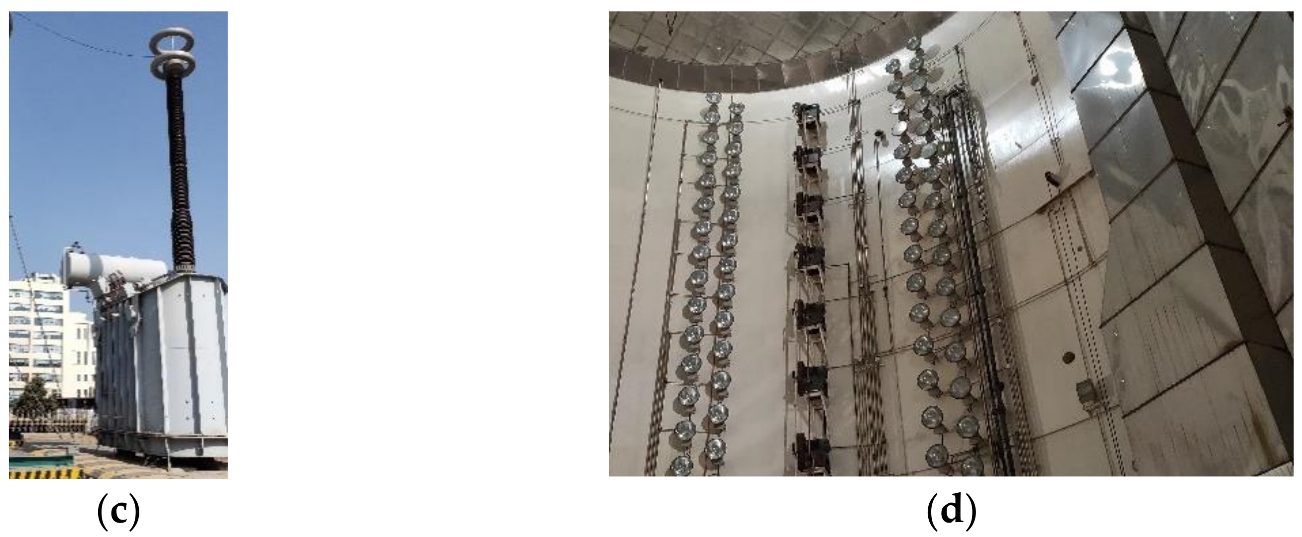
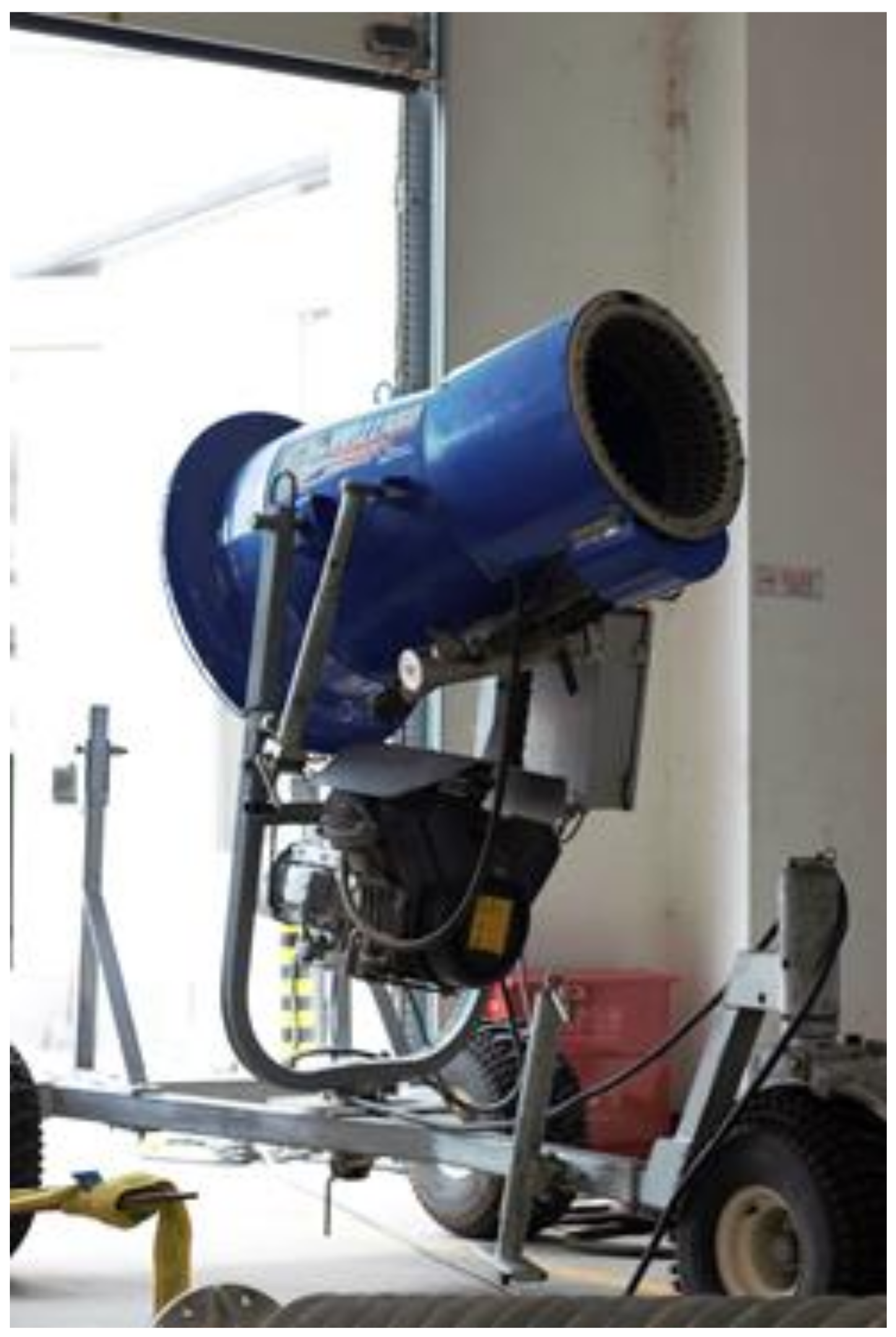
2.1. Experimental Setup
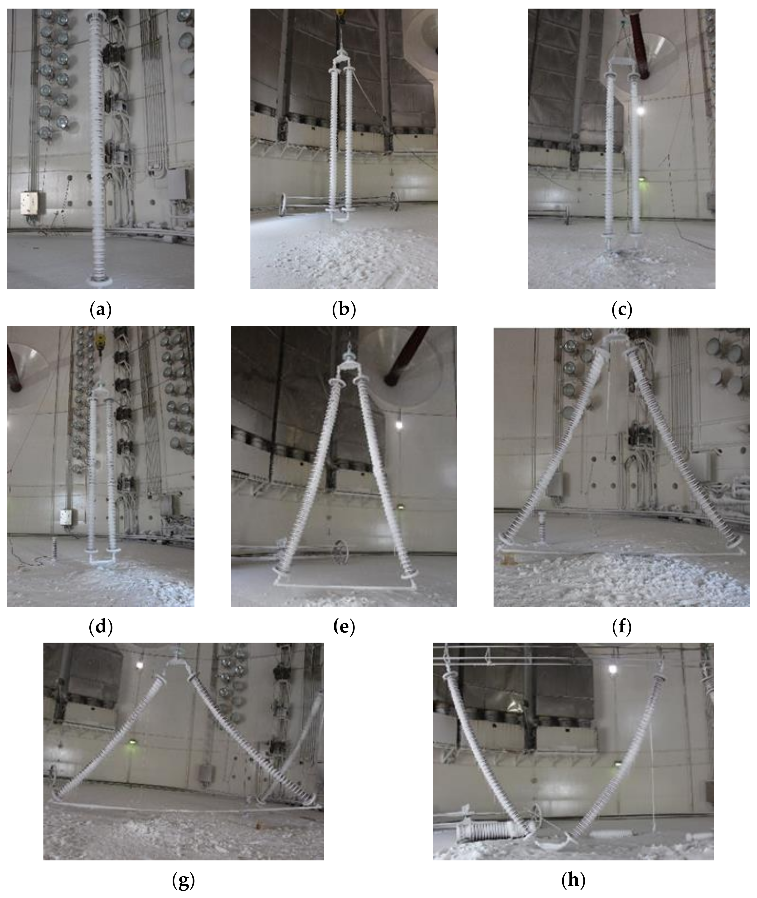
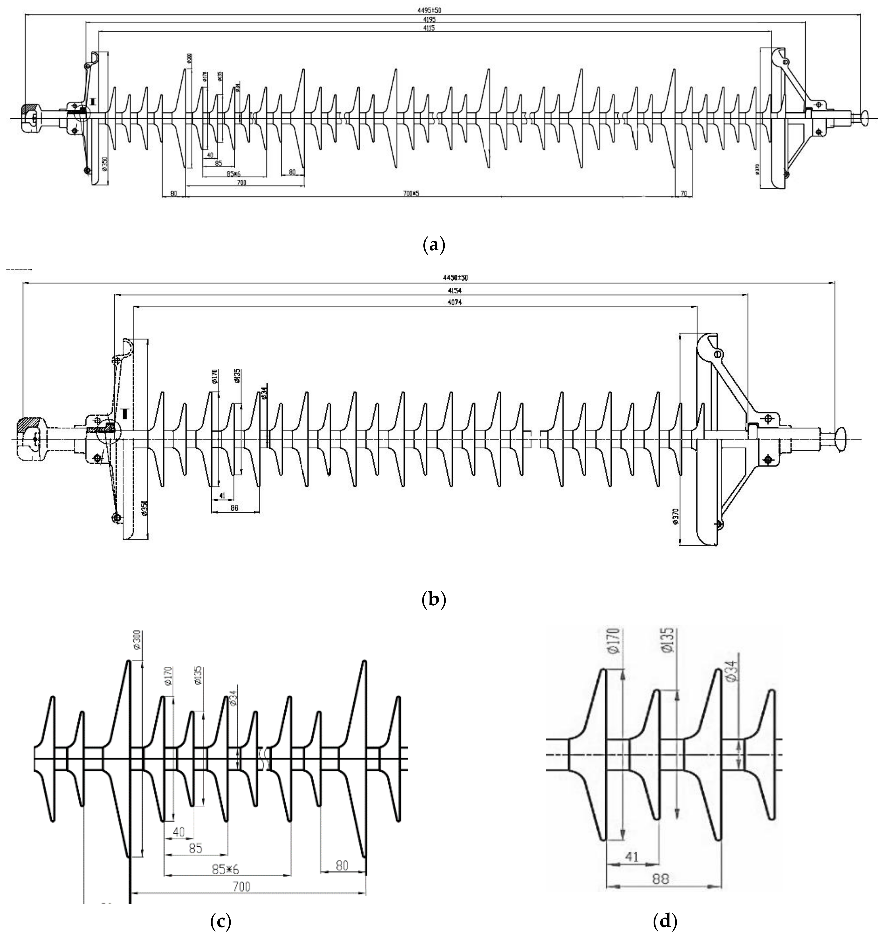
The wet snow flashover tests were carried out in a large artificial climate chamber of China Electric Power Research Institute (CEPRI) in Beijing, as shown in Figure 1. The chamber has a diameter of 22 m and a height of 34 m. It consists of a power system, cooling system, water spraying system, and ice melting system. Various conditions can be achieved such as high altitude, low air temperature, heavy fog, ice, rain, and snow. An altitude from 0 m to 5500 m and an ambient temperature from 0 °C to −19 °C can be simulated in the chamber. The power supplier for the flashover test was an AC test transformer with capacity of 800 kV/6 A.
To simulate snowstorms, a snow cannon as displayed in Figure 2 was used to produce the wet snow. The technical parameters of the snow canon are listed in Table 1.

2.2. Specimen

In this study, two kinds of insulators were tested in the experiments. One was a common type named FXBW-500/210 and the other one was an anti-icing type made by adding big sheds to the common type insulator. The profiles of both types are shown in Figure 3 and their profile parameters are listed in Table 2. Three types of insulator string arrangements, namely V-string, Λ-string, and II-string configurations, were tested, as illustrated in Figure 4. For the Λ-string configuration, insulator string connection angles of 2°, 30°, 60°, and 90° were tested. In Figure 4d, 450 mm and 600 mm are the distances between two strings at earth and energized ends, respectively. In Figure 4c, both insulator strings are vertical with a distance of 650 mm between them. The V-string configuration with connection angle of 60° was also investigated, as shown in Figure 4h.

2.3. Test Procedure

The pollution deposited on the insulator surface has two main components, namely soluble pollution that forms a conductive layer when wetted, and non-soluble pollution that forms a binding layer for the soluble pollution [20,21]. The flashover performance of the insulator is closely related to the soluble pollution component and its electrical conductivity is normally expressed as equivalent salt deposit density (ESDD). The insoluble fraction of the pollution layer is commonly reported as non-soluble deposit density (NSDD). To simulate the actual pollution level in Tianjin during the flashover test, detailed measurements of ESDD and NSDD were carried out on exposed field insulators. The measured average ESDD and NSDD were 0.1 mg/cm2 and 0.6 mg/cm2, respectively. This result confirmed that Tianjin, a coastal city, is exposed to a severe combination of salt and dust, and that its pollution level could be classified as Heavy according to the standardization adopted in IEC TS 60815 [20].
The test procedure adopted was in accordance with GB T 4585, IEC 60507, and IEEE Std 1783–2009 [22,23,24], and can be described as follows:
1) Pre-contamination
First, the insulator strings are carefully cleaned and dried. Before the first contamination, insulator strings are washed with a slurry of water and kaolin, and then rinsed with tap water. When dried, the specimens are artificially contaminated using the solid layer method with the measured ESDD and NSDD as mentioned above [20]. Then, the specimens are dried naturally for 24 hours.
2) Wet snow accretion
The specimens are suspended in the climate chamber in a desired arrangement, as shown in Figure 4. To deposit the wet snow, the climate chamber is first cooled down to a preset temperature of −16 °C and then kept constant. The water used for spraying has a conductivity of 100 μs/cm and is precooled to 4–5 °C before the spraying. After the preset temperature is reached, one hour is allowed for temperature stabilization. Then, the snow cannon is turned on to produce the wet snow. The water supply pressure is set at 280 PSI and the snow production is 20 m3/h.
Under the above-mentioned conditions, the measured liquid water mass fraction of wet snow was 20–25%. As icing degree is an important factor that influences the flashover voltage, each wet snow accretion lasted 20 min for the same snowing degree to be obtained. At this snowing degree, more than 90% of the single string with common sheds was bridged, as shown in Figure 4a. After that, the temperature of the chamber was kept constant at −16 °C for another 15 min to harden the snow. Finally, the chamber door was opened to increase the ambient temperature to 0 °C at 3 °C/h.
3) Wet snow flashover test
Using the even-rising method, the average flashover voltage was obtained for the various insulator string arrangements in the wet snow condition. First, the voltage was increased at a rate of 5 kV/s until flashover. Then, the chamber temperature was lowered to re-freeze the snow on the insulator surface for about 5 min. After that, the flashover test was repeated. Each wet snow accreted was exposed to voltage 3–5 times and the snow accretion of each insulator string arrangement was performed at least 4–5 times. As the flashover voltage was very scattered in the wet snow flashover tests, only those having a relative difference lower than 7.5% were considered as a valid test. To get the average flashover voltage, at least 10 valid tests should be performed. Then, the average flashover voltage Uave and the standard deviation σ can be expressed as:
U a v e = i = 1 N U f i N ,
σ = i = 1 N ( U f i U a v e ) 2 N 1 × 100 U a v e %
where N is the number of valid flashover tests, and Ufi (kV) is the flashover voltage of ith valid test.

3. Results

The test results are listed in Table 3. As the growth of snow, ice, and icicles is very random, the standard deviation can reach 17.3%, which is scattered much more than that of the pollution flashover test [25]. To make comparisons, the flashover of the single string insulator with common sheds is taken as the reference value. Then, the voltage change ratio β is calculated as:
β = U a v e ( 2 ) U a v e ( 1 ) U a v e ( 1 ) × 100 % ,
where Uave(1) in kV is the average flashover voltage of the single vertical string with common sheds, which is 391.0 kV in this study, and Uave(2) in kV is the flashover voltage of the other arrangements.

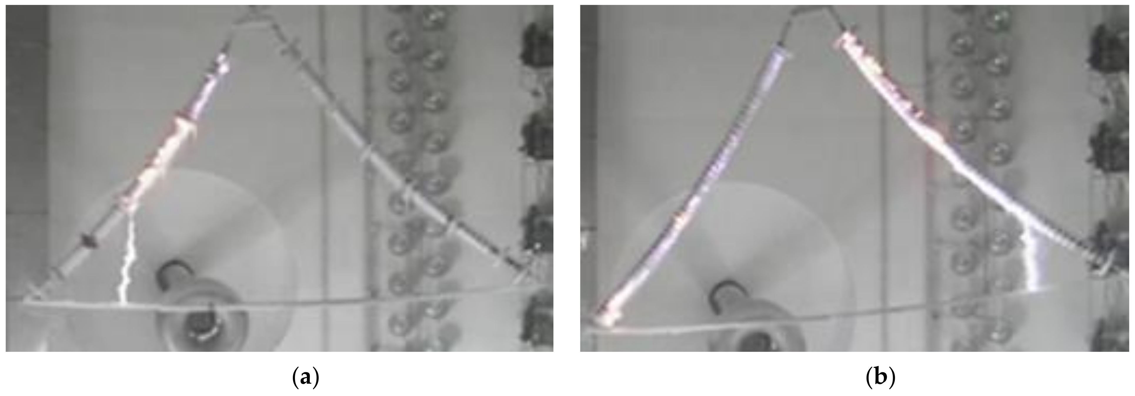
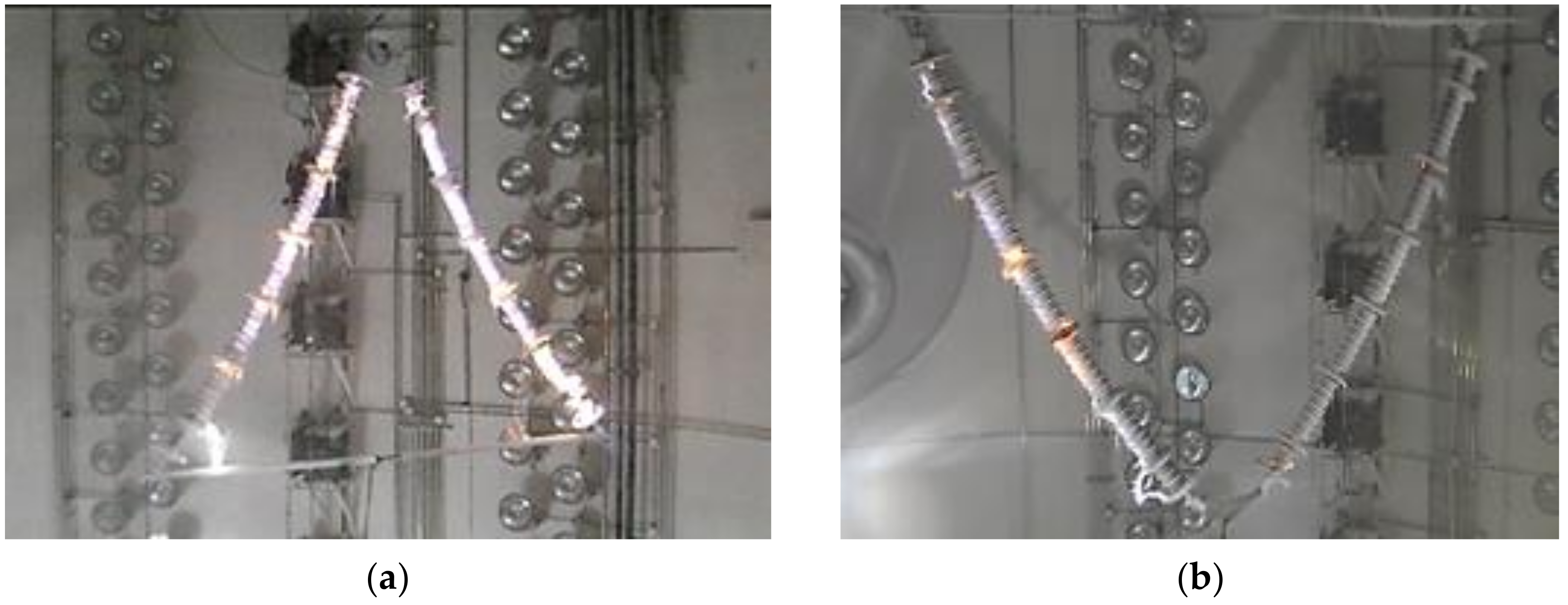
3.1. The Flashover Test of Λ-string

During the test, the insulators were covered with snow and ice, which had negative effect on their electrical performance. To investigate the electric field distribution, numerical simulations were carried out using finite element method by ANSYS Maxwell with electrostatic as the solver. The parameters used in the electric field calculation model are listed in Table 4 [26,27,28]. The simulation was performed in 2D. In the simulation, the snowed insulators were placed in a square with side length of 50 m. The high voltage was applied to the high-voltage ends of the insulators while the earth ends of the insulators and four sides of the square were grounded. When the ambient temperature was raised to around 0 °C, ice and snow started to melt and a water film formed on their surface. The water film was assumed uniform in the simulation. As this simulation calculated the electric field distribution before flashover, static electric field was also assumed. The relative permittivity of the water film was set at 81 and snow layer was set at 6.0. The length of icicles on anti-icing sheds was set at 300 mm. To set the value of water volume conductivity, a water collector was placed under the insulator to collect and measure the melted water during the flashover test. The average water conductivity was about 670 µS/cm. The simulated results of the 90° Λ-string arrangement with anti-icing shed are shown in Figure 5. It can be seen that the electric field concentrates on the terminals of insulator strings, and is distorted at the icicle tips. Areas with high electric field strength are susceptible to partial discharge, which poses a challenge for the safe operation of insulator strings.
To get a clear and visual comparison of the Λ-string configurations, the results are plotted in Figure 6, which makes it convenient to compare the wet snow flashover voltage for various arrangements and find tendencies. It can be seen from Figure 6 that, for the Λ-string configuration using common shed insulators, wet snow flashover voltage increases with an increase of the connection angle up to 90 °C. It is also observed that the slope of the black line (the common shed structure) decreases when the connection angle is higher than 60°. For anti-icing shed insulators, the wet snow flashover voltage increases as the connection angle increases up to 60°, and then deceases when the connection angle increases further. The reason for an improved flashover performance of the tilted insulator string configuration is obvious. If the insulator string is placed at vertical, the air gaps formed by the ice and icicles can be easily shorted and insulator sheds can even be bridged in the worst case. When the insulator string is tilted, the formed vertical icicles have an angle with the insulator string and the insulator shed cannot be bridged as easily as under the vertical configuration.
For the red line (the anti-icing shed structure), there are two points to be noticed. One is 2° at which the flashover voltage increases dramatically compared with that of vertical arrangement and the other is 90° at which the flashover voltage is even lower than that at 60°. When the connection angle was changed from 0° to 2°, there was an increase of 150 mm in the horizontal distance between two high voltage terminals and a voltage increase of 18.7 kV. Although the increase of distance was minor, it had a great influence on the flashover process. Due to the larger diameter of the anti-icing sheds, there were always floating arcs between the two insulators when the distance between the two high-voltage terminals was 450 mm during the flashover tests. Increasing the distance between high voltage terminals can make the arc develop relatively independently and therefore increase the flashover voltage.
The discharge paths of iced insulator strings with anti-icing sheds and common sheds are shown in Figure 7a,b. It can be seen that both discharge paths are shorter than their leakage distances. For the anti-icing insulator at the left side of Figure 7a, the air gap between the icicles of the third big sheds from the high voltage end and the conductor is shorted by the arc, which is much longer than the arc in air of the common shed insulator in Figure 7b. The morphology of the 90° arrangement with anti-icing sheds is shown in Figure 8. Due to the large diameter of the anti-icing sheds, the deposited snow on the large sheds is more than that on the common sheds. Furthermore, the water in the snow flows to the bottom of the inclined sheds to form icicles up to 300-mm long. Thus, the top of the inclined sheds appears white while the lower end is translucent, as shown in Figure 8. With the increase of connection angle, the insulator sheds are even harder to bridge. This is a positive factor for the insulator flashover performance. However, as the icicles on the anti-icing shed are very long, combined with a smaller angle between the insulator string and conductor, the breakdown of the air gap between the icicles and the conductor is more likely to happen. According to the test results that flashover voltage is higher at the connection angle of the 60° than that of 90° arrangement, it can be concluded that, in this case, the icicle-conductor air gap shortening effect counteracts and even exceeds the effect of icicle bridging mitigation with the increase of connection angle.
The flashover performance of the Λ-string arrangement with that of the V-string arrangement at a connection angle of 60° is also compared, as plotted in Figure 9. It can be seen from the figure that, for common shed insulators, the flashover voltages of the 60° Λ-string and 60° V-string arrangements are almost the same. For the insulators with anti-icing sheds, the flashover voltage of the 60° Λ-string arrangement is obviously lower than that of the 60° V-string arrangement. As the connection angles of the Λ-string and V-string arrangements are same, the severity of ice bridging is almost same for the same snowing condition. For common shed insulators, as discharge directly from the snowed insulator shed to the conductor was not observed, the flashover voltages of the Λ-string and V-string arrangements are therefore almost the same. When it comes to the anti-icing shed insulators, with the presence of long icicles, the discharge from icicles accreted on big sheds to the conductor happened more readily for the Λ-string arrangement. As illustrated in Figure 10, there was an air gap shortening effect in the arc development process of the 60°Λ-string arrangement, while the arc of 60° V-string developed almost only along the insulator string. Therefore, it can be concluded that the flashover voltage of the 60° Λ-string arrangement is lower than that of the 60° V-string arrangement.

3.2. The Flashover Test of II-String

In this study, wet snow flashover tests of II-string with different distance between two insulator strings were performed to find an appropriate insulator distance in wet snow conditions.
For insulator strings with common sheds, it was observed that when the distance between two high-voltage terminals is not less than 600 mm, the development of flashover arcs is relatively independent. From the test results, it can also be confirmed that the flashover voltages of two arrangements, 650 mm II-string and 2° Λ- string (450–600 mm string), are almost the same due to the absence of floating arcs. Because of an increased flashover probability, as mentioned above, their flashover voltages are 1.3%–2.4% lower than those of single strings.
For the insulator string with anti-icing sheds, examples of discharge paths are shown in Figure 11. From the experiments, it was noticed that there were always multiple floating arcs bridging two insulator strings for the 450-mm II-string arrangement. These floating arcs shorten the discharge path greatly and lead to lower flashover voltages among all arrangements in this study.
For the 450–600 mm II-string arrangement, there was only one flashover arc floating between to insulators as shown in Figure 11b, making the flashover voltage higher than that of the 450 mm II-string arrangement.
Above all, a longer distance between two insulator strings can prevent floating arcs. Whether the flashover arc of an individual insulator can develop relatively independently or not is a key factor to judge whether the distance between the two insulator strings is appropriate.
According to the test results, it is suggested that, for the insulators under study, the distance between the two high-voltage terminals should be at least 600 mm for the insulator string with common sheds and at least 650 mm for the insulator string with anti-icing sheds.

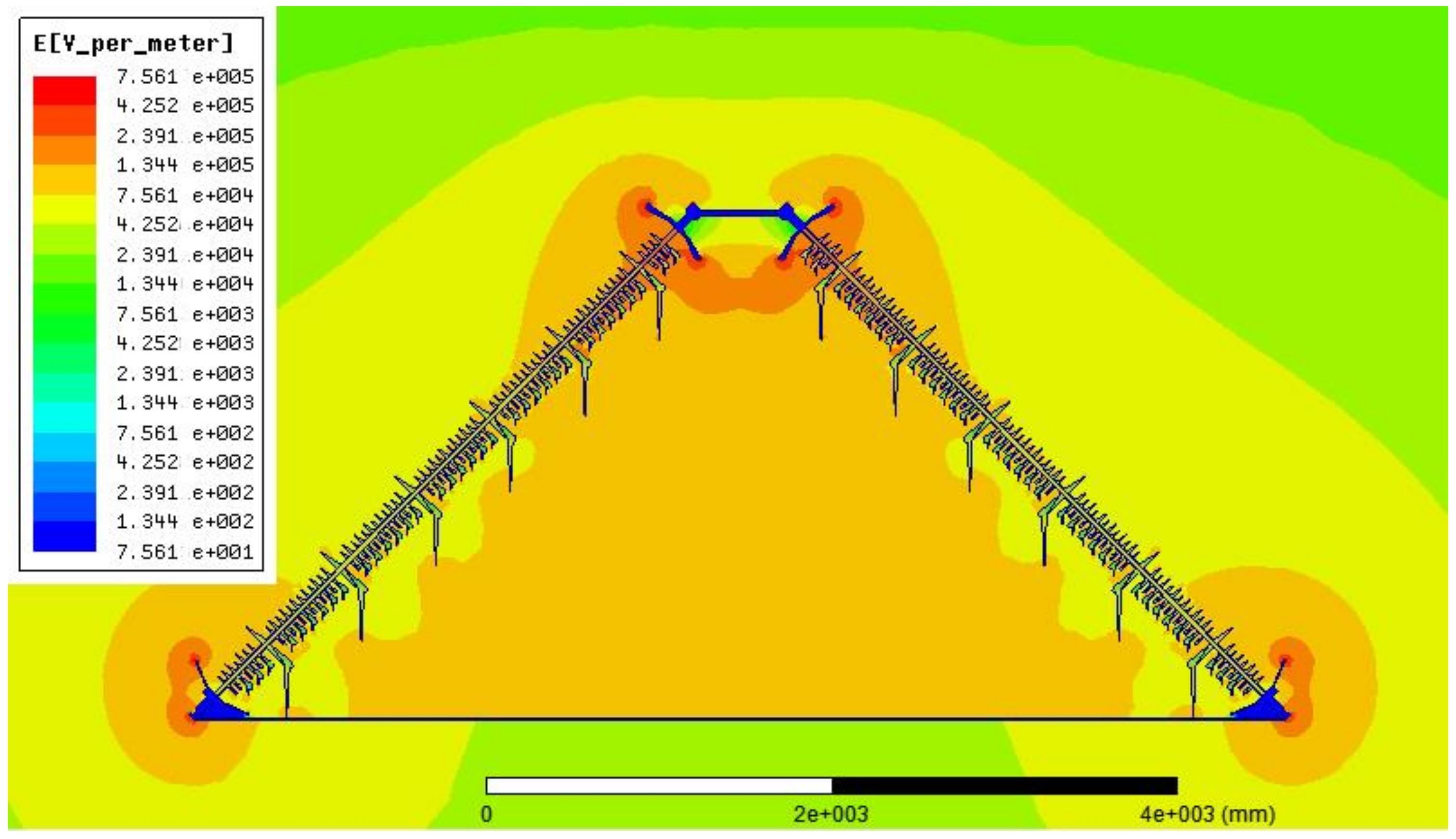
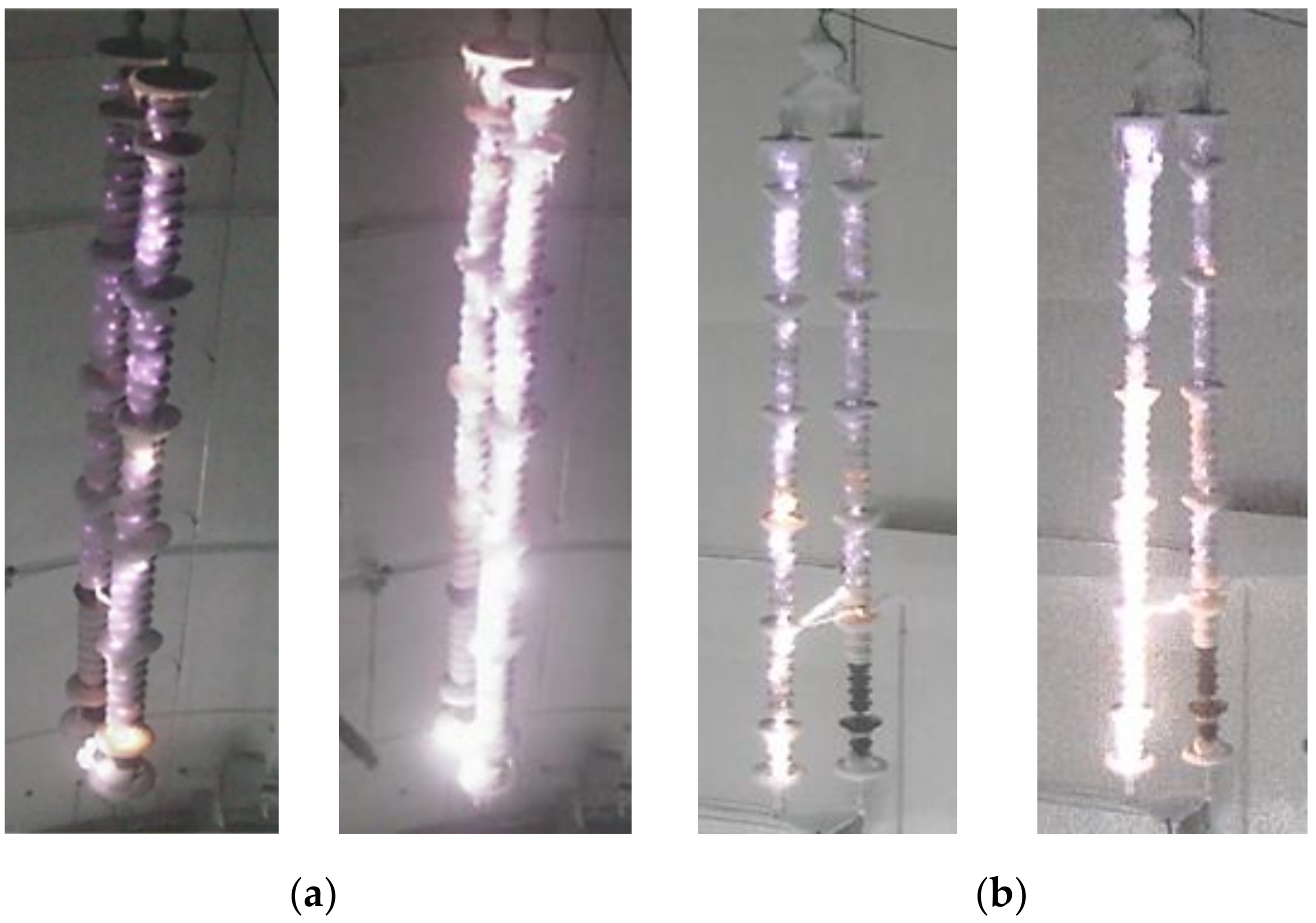
3.3. The Influence of Shed Type on Flashover

From Figure 12, it can be seen that, for every arrangement, the flashover voltage of the insulator string with anti-icing sheds is higher than that with common sheds. For the 90° Λ-string arrangement, due to the discharge from icicles to wire, the flashover voltage of the insulator string with anti-icing sheds is 7.6% higher than that with common sheds. For the other arrangements, the flashover voltage improvement ranges from 11.0% to 19.5%.
In order to explain the test results, an equivalent circuit model is shown in Figure 13 where Ci and Ri are the capacitance and resistance of the insulator string, CLi is the stray capacitance to high voltage, and CEi is the stray capacitance to ground.
It is well known that Ci and Ri are decreased in snowing conditions, which aggravates the stray capacitance disturbance to the distribution of voltage along the insulator string. However, adding the anti-icing sheds, which can create air gaps, will counteract the decrease of Ci and Ri. Therefore, the flashover voltage improvement of anti-icing sheds can be explained by the following reasons:
(1)
The insulation distance of the insulator string with anti-icing sheds is a little longer than that with common sheds for all arrangements.
(2)
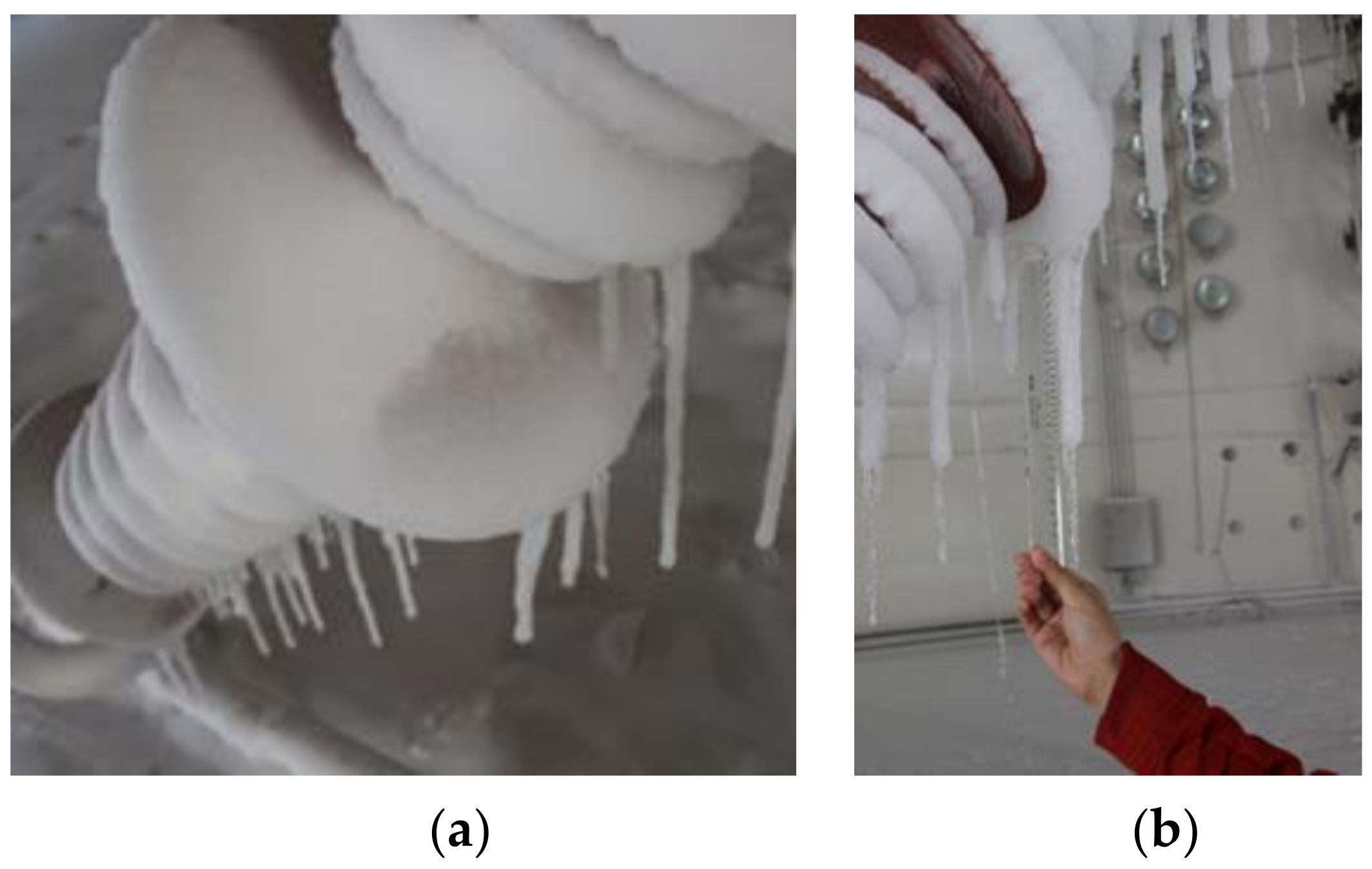
The anti-icing sheds, due to their larger diameter, can hinder or delay the arc development.
(3)
Compared with an insulator string with common sheds, the air gaps between big sheds can increase the capacitance of the snowed insulator string. As a larger insulator capacitance can weaken the influence of stray capacitance, the distribution of voltage along the insulator string will be relatively uniform and result in a higher flashover.

4. Conclusions

Based on the tests carried out in this paper, the following conclusions can be drawn:
  • Installing anti-icing sheds is an effective method to improve the flashover performance of insulators used in cold regions.
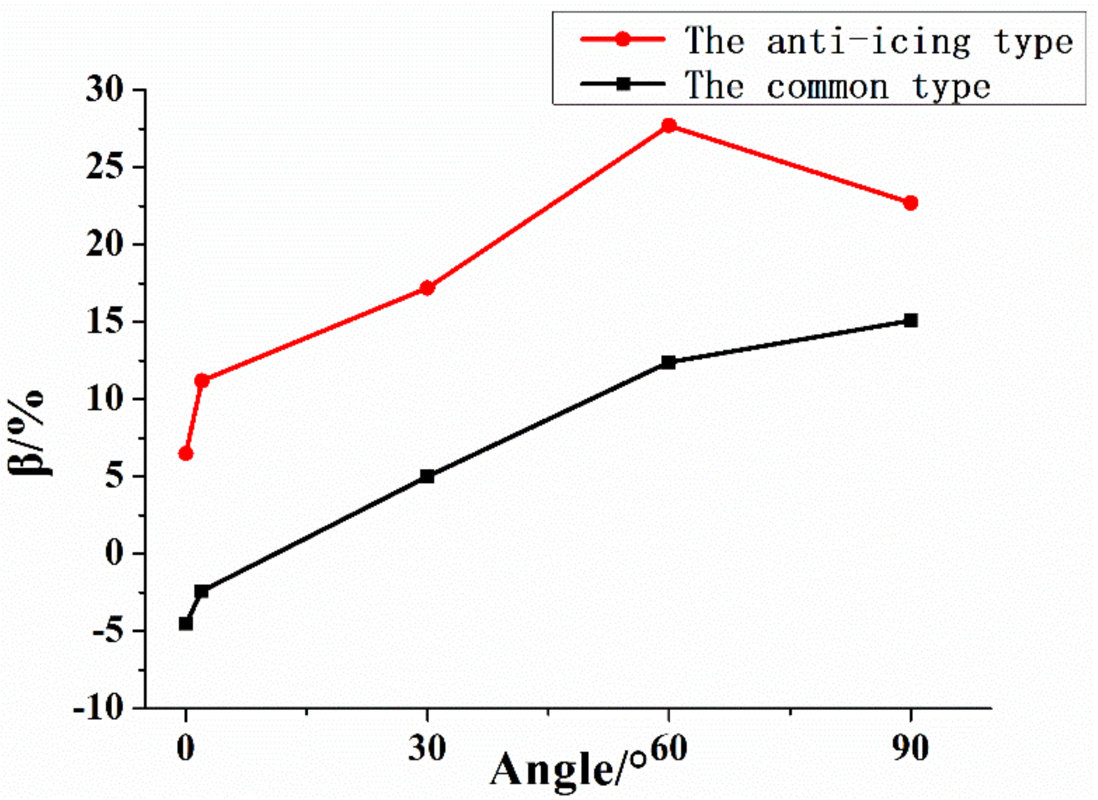
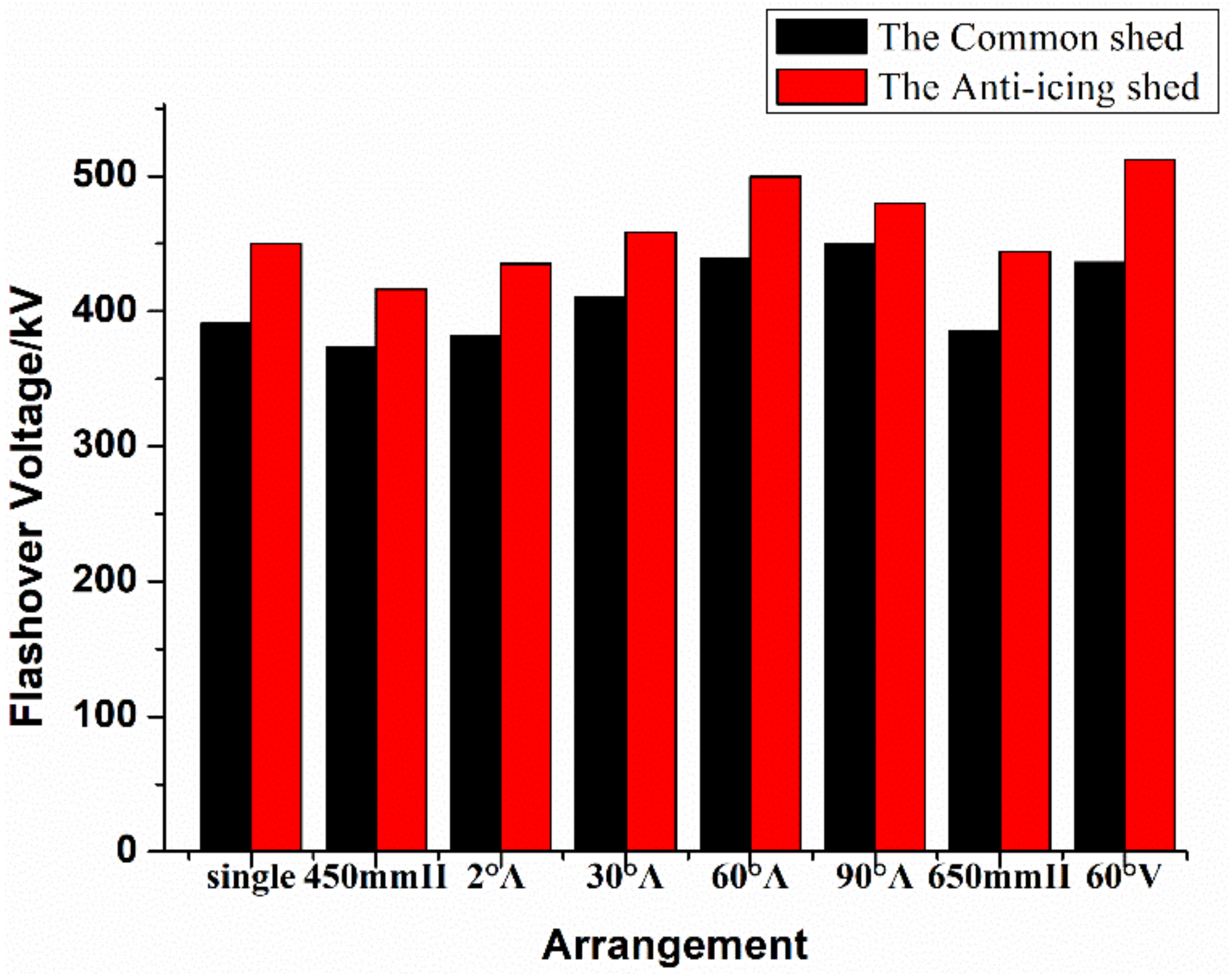
  • Increasing the connection angle can reduce the severity of snow bridging, and therefore increase the flashover performance of insulators with common sheds as the connection angle is increased. However, it was found that for insulators with anti-icing sheds and connection angle higher than 60°, with a small angle between the insulator string and the conductor, the air gap between the icicle and the conductor can breakdown readily if long icicles are accreted on the big shed. According to the test results, when it comes to the electrical performance, the recommended connection angles for Λ-string arrangements with common sheds and with anti-icing sheds are 90° and 60°, respectively.
  • Increasing the distance between two insulators can improve the flashover voltage performance. When the distance between the two insulators is too close, the flashover voltage will be reduced due to the floating arcs bridging two parallel insulators. For an II-string arrangement, when the distance was increased from 450 mm to 650 mm, the flashover voltages were increased 3.2% and 7.1% for common shed and anti-icing shed insulators. The recommended distance between the two high-voltage terminals is at least 600 mm for the strings with common sheds and at least 650 mm for the strings with anti-icing sheds.
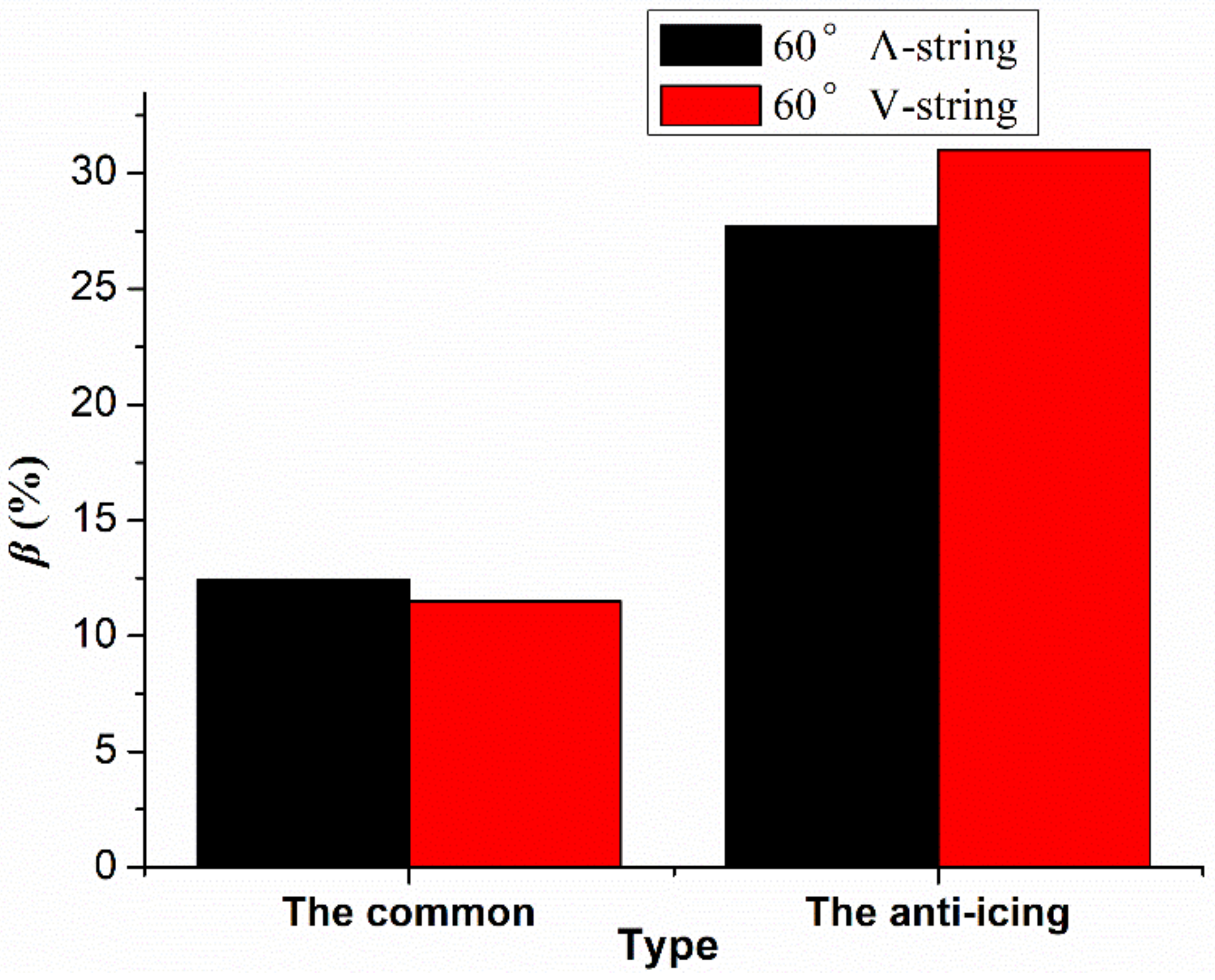
  • When the connection angle is 60°, which is widely adopted in transmission lines, the flashover performance of common insulators under Λ-string and V-string arrangements are almost same for the same snowing conditions. However, due to the presence of long icicles, the flashover voltage of anti-icing insulators under a V-string arrangement is higher than that of a Λ-string arrangement.

Author Contributions

Conceptualization, Z.J.; investigation, J.X., L.L., Q.W. and S.L.; data curation, H.W.; writing—original draft preparation, J.X. and F.Y.; writing—review and editing, F.Y. and M.F.; project administration, Z.J.

Funding

The project was supported by the National Natural Science Foundation of China (51777107) and the Guangzhou Industry-university-research Collaborative Innovation Alliance Special Project (201604046014).

Acknowledgments

The authors would like to thank the technicians from China Electric Power Research Institute for their invaluable help in carrying out the experiments.

Conflicts of Interest

The authors declare no conflict of interest.

References

  1. Farzaneh, M. Atmospheric Icing of Power Networks; Springer: Dordrecht, The Netherlands, 2008. [Google Scholar]
  2. Farzaneh, M.; Chisholm, W.A. Insulators for Icing and Polluted Environments; John Wiley & Sons Press: Piscataway, NJ, USA, 2009. [Google Scholar]
  3. Yin, F.; Farzaneh, M.; Jiang, X. Influence of AC electric field on conductor icing. IEEE Trans. Dielectr. Electr. Insul. 2016, 23, 2134–2144. [Google Scholar] [CrossRef]
  4. Yin, F.; Jiang, X.; Farzaneh, M. Electrical performance of composite insulators under icing conditions. IEEE Trans. Dielectr. Electr. Insul. 2014, 21, 2584–2593. [Google Scholar] [CrossRef]
  5. Hu, J.; Jiang, X.; Yin, F.; Zhang, Z. DC flashover performance of ice-covered composite insulators with parallel air gaps. Energies 2015, 8, 4983–4999. [Google Scholar] [CrossRef]
  6. Berlijn, S.; Gutman, I.; Halsan, K.; Eilertsten, M.; Gu, I.Y.H. Laboratory tests and web based surveillance to determine the ice-and snow performance of insulators. IEEE Trans. Dielectr. Electr. Insul. 2007, 14, 1373–1380. [Google Scholar] [CrossRef]
  7. Farzaneh, J.; Zhang, J.; Farzaneh, M. Experimental study and mathematical modelling of flashover on extra-high voltage insulators covered with ice. Hydrol. Proc. 2004, 18, 3471–3480. [Google Scholar] [CrossRef]
  8. Farzaneh, M.; Baker, T.; Bernstorf, A.; Burnham, J.T.; Carreira, T.; Cherney, E.; Chisholm, W.; Christman, R.; Cole, R.; Cortinas, J.; et al. Selection of station insulators with respect to ice and snow—Part I: Technical context and environmental exposure. IEEE Trans. Power Deliv. 2005, 20, 264–270. [Google Scholar] [CrossRef]
  9. Farzaneh, M.; Baker, T.; Bernstorf, A.; Burnham, J.T.; Carreira, T.; Cherney, E.; Chisholm, W.; Christman, R.; Cole, R.; Cortinas, J.; et al. Selection of station insulators with respect to ice and snow—Part II: Methods of selection and options for mitigation. IEEE Trans. Power Deliv. 2005, 20, 271–277. [Google Scholar] [CrossRef]
  10. Farzaneh, M.; Baker, A.C.; Bernstorf, R.; Burnham, J.T.; Carreira, T.; Cherney, E.; Chisholm, W.; Christman, R.; Cole, R.; Cortinas, J.; et al. Selection of line insulators with respect to ice and snow—Part II: Selection methods and mitigation options. IEEE Trans. Power Deliv. 2007, 22, 2297–2304. [Google Scholar] [CrossRef]
  11. Xun, K.; He, C.; Du, Y.; Yuan, Z. Development and application of transmission line inversed V-shape insulator string. Electr. Power Construct. 2008, 29, 31–34. [Google Scholar]
  12. Guan, Z.; Peng, G.; Zhao, F. DC pollution flashover characteristics on porcelain insulators of parallel double-strings form at high altitude. High Voltage Eng. 2010, 36, 2613–2620. [Google Scholar]
  13. Zheng, J. Research on optimum angle of the insulator strings in “Λ” shape on 500 kV transmission lines. J. Electr. Power 2010, 25, 328–331. [Google Scholar]
  14. Zhang, C.; Wang, L.; Zhou, J. AC and DC pollution flashover performance of multiple parallel suspension insulators. High Volt. Eng. 2014, 40, 3357–3364. [Google Scholar]
  15. Zhao, Q.; Xu, W.; Liu, W.; Zhou, K. Application suggestion and force analysis of backward V-type insulators. Smart Grid 2017, 5, 142–146. [Google Scholar]
  16. Wei, M.; Huo, F.; Ruan, J.; Huang, C.; Wan, X. Study on electric field distribution and grading ring’s parameters design of backward V-type insulator string on UHV AC transmission line. Adv. Technol. Electr. Eng. Energy 2016, 35, 23–28. [Google Scholar]
  17. Yan, S.; Wan, Q.; Xu, Z. Experimental study on the flashover characteristics of 500 kV AC ice-covered insulator string under different arrangement. High Volt. Eng. 2011, 37, 3129–3134. [Google Scholar]
  18. Ma, K.; Li, G.; Yang, W.; Ma, B. Test on power frequency flashover property of 110 kV single and double composite insulator strings. Ningxia Electr. Power 2011, 6, 22–25. [Google Scholar]
  19. Hu, W.; Huo, F.; Xu, T.; Nan, J.; Ye, Q.; Ma, Y. Air-gaps flashover characteristics and insulation coordination of inverse V-type insulator string tower for UHV AC transmission line. High Volt. Eng. 2017, 43, 4117–4122. [Google Scholar]
  20. IEC TS 60815-1. Selection and Dimensioning of High-Voltage Insulators Intended for Use in Polluted Conditions—Part 1: Definitions, Information and General Principles; International Electrotechnical Commission: Worcester, MA, USA, 2008. [Google Scholar]
  21. IEC TS 60815-3. Selection and Dimensioning of High-Voltage Insulators Intended for Use in Polluted Conditions—Part 3: Polymer Insulators for a. c. Systems; International Electrotechnical Commission: Worcester, MA, USA, 2008. [Google Scholar]
  22. GB T 4585. Artificial Pollution Tests on High-Voltage Insulators to Be Used on AC Systems; Standards Press of China: Beijing, China, 2004. [Google Scholar]
  23. IEC 60507:2013. Artificial Pollution Tests on High-Voltage Insulators to Be Used on a. c. Systems; International Electrotechnical Commission: Worcester, MA, USA, 2013. [Google Scholar]
  24. IEEE Std 1783-2009. IEEE Guide for Test Methods and Procedures to Evaluate the Electrical Performance of Insulators in Freezing Conditions; Institute of Electronics Engineers: New York, NY, USA, 2009. [Google Scholar]
  25. Li, Z.; Cui, J.; Zhou, Y.; Wang, L. Influence of insulator installation form on its pollution flashover voltage. Power Syst. Technol. 2005, 29, 52–55. [Google Scholar]
  26. Zhang, Z.; Zhang, D.; You, J. Study on the DC flashover performance of various types of insulators with fan-shaped nonuniform pollution. IEEE Trans. Power Deliv. 2015, 30, 1871–1879. [Google Scholar] [CrossRef]
  27. Taherian, R.; Kausar, A. Electrical Conductivity in Polymer-Based Composites: Experiments, Modelling, and Applications; William Andrew Publisher: Oxford, UK, 2019. [Google Scholar]
  28. Volat, C.; Farzaneh, M. Three-dimensional modeling of potential and electric-field distributions along an EHV ceramic post insulator covered with ice—Part I: Simulations of a melting period. IEEE Trans. Power Deliv. 2005, 20, 2006–2013. [Google Scholar] [CrossRef]
Figure 1. The experimental setup. (a) Climate chamber, (b) Divider, (c) Transformer, (d) Lamps for ice melting
Applsci 09 00930 g001aApplsci 09 00930 g001b
Figure 2. The snow cannon used for wet snow accretion on insulator strings.
Applsci 09 00930 g002
Figure 3. Profiles of FXBW-500/210. (a) Schematic diagram of the anti-icing unit, (b) Schematic diagram of the common unit, (c) Detailed dimension of the anti-icing unit, (d) Detailed dimension of the common unit.
Applsci 09 00930 g003
Figure 4. Various arrangements examples of snow-covered insulator strings: (a) Single string, (b) 450 mm II-string, (c) 650 mm II-string, (d) 2° Λ-string (450 mm-600 mm string), (e) 30° Λ-string (450 mm string), (f) 60° Λ-string (450 mm string), (g) 90° Λ-string (450 mm string), (h) 60° V-string (450 mm string)
Applsci 09 00930 g004
Figure 5. Model of the 90° Λ-string.
Applsci 09 00930 g005
Figure 6. Relationship between the voltage change ratio β and connection angle for the common and anti-icing sheds
Applsci 09 00930 g006
Figure 7. The flashover arcs of Λ-string. (a) The 90° with anti-icing sheds, (b) The 90° with common sheds.
Applsci 09 00930 g007
Figure 8. The morphology of ice accreted on the anti-icing sheds when the connection angle is 90°.
Applsci 09 00930 g008
Figure 9. The comparison of voltage change ratio β between Λ-string and V-string.
Applsci 09 00930 g009
Figure 10. The arcs of Λ-string and V-string with anti-icing shed. (a) The 60°Λ-string, (b) The 60° V-string.
Applsci 09 00930 g010
Figure 11. The flashover path of II-string. (a) 450 mm II-string, (b) 2° Λ-string (450 mm–600 mm string).
Applsci 09 00930 g011
Figure 12. Comparison voltage change ratio β between the common shed and the anti-icing shed.
Applsci 09 00930 g012
Figure 13. Equivalent circuit model of insulator string.
Applsci 09 00930 g013
Table 1. Parameters of the snow cannon.
ParametersValue
Power voltage380 V
Air supply pressure90 PSI
Water supply pressure105–500 PSI
Snow production capacity0–30 m3/h
Operating temperature0–30 °C
Table 2. Parameters of the common and anti-icing insulators.
Shed TypeArcing Distance
(mm)
Leakage Distance (mm)Shed Diameters D1/D2/D3 (mm)Shed Numbers
N1/N2/N3
Rod Diameter
D (mm)
Shed Spacing d1/d2/d3/d4 (mm)
The anti-icing type419514,000300/170/1356/35/363440/45/70/80
The common type415414,000170/13546/473441/47
Table 3. Flashover voltage of various arrangements.
String ArrangementsCommon ShedAnti-Icing Shed
Flashover Voltage (kV)σ (%)β (%)Flashover Voltage (kV)σ (%)β (%)
Single string391.015.50.0450.05.115.1
II-string(450 mm)373.55.1−4.5416.33.36.5
2°Λ-string381.510.1−2.4435.012.211.2
30°Λ-string410.61.25.0458.29.417.2
60°Λ-string439.411.812.4499.57.327.7
90°Λ-string450.113.715.1479.813.222.7
II-string(650 mm)385.617.3-1.3444.32.613.6
60°V-string436.05.211.5512.36.731.0
Table 4. Parameters used in the simulation model.
ParametersSilicone RubberIceSnowWater FilmAir
Relative permittivity, εr6.0706.0811.02
Conductivity (μS/cm)011006700
Thickness (mm)-VariableVariable0.15-

