Article

Multi-Robot Trajectory Planning and Position/Force Coordination Control in Complex Welding Tasks

1
School of Automation, Southeast University, Nanjing 210096, China
2
Key Lab of Measurement and Control of Complex Systems of Engineering, Ministry of Education, Nanjing 210096, China
*
Author to whom correspondence should be addressed.
Appl. Sci. 2019, 9(5), 924; https://doi.org/10.3390/app9050924
Submission received: 12 December 2018 / Revised: 22 February 2019 / Accepted: 27 February 2019 / Published: 5 March 2019
(This article belongs to the Special Issue Advanced Mobile Robotics)

Abstract

:
In this paper, the trajectory planning and position/force coordination control of multi-robot systems during the welding process are discussed. Trajectory planning is the basis of the position/ force cooperative control, an object-oriented hierarchical planning control strategy is adopted firstly, which has the ability to solve the problem of complex coordinate transformation, welding process requirement and constraints, etc. Furthermore, a new symmetrical internal and external adaptive variable impedance control is proposed for position/force tracking of multi-robot cooperative manipulators. Based on this control approach, the multi-robot cooperative manipulator is able to track a dynamic desired force and compensate for the unknown trajectory deviations, which result from external disturbances and calibration errors. In the end, the developed control scheme is experimentally tested on a multi-robot setup which is composed of three ESTUN industrial manipulators by welding a pipe-contact-pipe object. The simulations and experimental results are strongly proved that the proposed approach can finish the welding task smoothly and achieve a good position/force tracking performance.

1. Introduction

With the complication and diversification of industrial production tasks, multi-robot cooperative systems have demonstrated stronger operational capabilities, more flexible system structures, and stronger collaboration capabilities. Therefore, multi-robot collaboration has become an important challenge for robot control.
Multi-robot collaboration has been applied in many fields such as handing, assembly, welding, etc. The application of this paper is focused on the welding field. In arc welding, the traditional welding workstation consisting of “welding robot + positioner” is not able to meet the current demand for small-volume, customized, flexible, and automated production. Multi-robot cooperative welding adopts a universal and high-degree of freedom handing robot instead of a low-degree of freedom positioner, which can effectively improve the flexibility of welding tasks and welding automation.
Arc welding is a complex system that contains both pose constraints and wrench constraints, the use of multi-robot systems for arc welding has many advantages, but it also brings more complex control problems. Two of the most critical issues are the trajectory planning in the multi-robot collaboration process and the coordinated control of position/force among multi-robot.
For the trajectory planning of multi-robot systems, the current research issues include motion constraints, control methods for cooperative motion, and implementation of multi-robot cooperative systems.
(1) For the motion constraint problem of multi-robot systems, the main task is to derive the end-effector of robot pose, velocity and acceleration constraints. For example, the idea is first pointed out in [1] that when two or more robots grab a common object, the robot end-effector is subject to kinematic constraints, and gives the speed constraint relationship of the multi-robot end-effector when the multi-robot is holding an object and rotates around its center. The pose, speed and acceleration constraints of the end-effector in the case of two robots grasp the common object, operate a pair of pliers and grab an object with a ball joint are deduced in [2,3]. The concept of absolute motion when the two robots cooperatively clamp the workpiece is proposed in [4]. The multi-robot cooperated trajectory planning approach based on the closed kinematic chain model is proposed in [5]; (2) For the control methods of collaborative movements, a method of establishing a constraint model with differential algebraic equations which using feedback linearization is addressed in [6]. The common control methods of general differential algebraic systems is summarized base on the above idea in [7]; (3) The realization for multi-robot collaboration system, the problem of trajectory planning and programming of general multi-robot cooperative system are analyzed. Such as ABB MultiMove function, KUKA RoboTeam function, Yaskawa independence/collaboration function, FANUC cooperative action function, etc.
Although the above research has given a certain impetus to the kinematics constraints and trajectory planning, the current multi-robot coordination tasks are relatively simple and most of them are focus on the coordination of dual robots. The above trajectory planning method is not scalable and feasible for multi-robot collaboration to accomplish specific tasks in a more complex and unstructured environment.
Multi-robot trajectory planning is the basis for completing the welding tasks, there are not only pose constraints, but also the wrench constraints in the process of welding displacement. Therefore, multi-robot position/force coordination control is another key issue in the cooperative welding process. Research methods for multi-robot position/force coordination control include master/slave control, hybrid motion/force control, synchronization control and impedance control. (1) Master/slave control. The control idea is to define one of the robotic arms as the master arm and the other as the salve arm. The master and the slave arm should’ve meet the certain constraints. The master arm is controlled by the position control mode, and the slave arm follows the motion trend of the master arm detected by the force/torque sensor mounted at the wrist of the slave arm. The master/slave force control approach for the coordination of two arms which carries a common object cooperatively was proposed in [8,9], and the necessity of force control for cooperative multiple robots is also pointed out. However, the slave arm needs to have a fast following response [10], otherwise it will lead to system instability. Force/torque sensor and position controller are difficult to achieve high-speed response in actual control systems. Therefore, the master-slave control strategy is only suitable for low-speed applications; (2) Hybrid motion/force control. The basic idea is that two arms work equally and coordinated by the centralized control. The position control is used in the free space, and the force control is used in the constrained space, such as [11,12,13,14]. A difficulty in implementing the hybrid control law in rigid environment is knowing the form of the constraints active at any time. And it also needs to sacrifice some performance by choosing low feedback gains, which makes the motion controller “soft” and the force controller more tolerant of force error; (3) Synchronization control. The basic idea is to track the desired trajectory which is generated by the desired force based on the dynamic model of the manipulators. The control problem is formulated in terms of suitably defined errors accounting for the motion synchronization between the manipulators involved in the cooperative task. The concept of motion synchronization was used in [15,16]. An adaptive control strategy was adopted to track the desired trajectory, ensuring the synchronization position errors converged to zero. In addition, intelligent control strategies were also used in the coordination control of nonlinear cooperative manipulator systems [17,18,19]. However, the synchronization control is based on the dynamic model. Although the synchronization error at the end effector of the manipulator was considered, due to the difficulties in dynamic modeling, over-complexity control model, strong coupling and nonlinearity, it has not been applied in most actual control systems; (4) Impedance control. The basic idea is to achieve the adjustment of the position based on the force error. Impedance control is a stable and effective method widely used in many fields including coordination. The coordination strategy of the object based on impedance control was studied in [20,21,22,23,24]. The force acting on the object was decomposed into the external force that contributes to the object’s motion and the internal force by the end-effector of both arms. Following the guidelines in above references, the external impedance and the internal impedance were combined in a unique control framework [25]. Compared with the first three control strategies, impedance control overcomes the shortcomings of the above control methods, and can effectively control the internal and external force.
In contrast, impedance control has been widely used in multi-robot position/force coordination control. However, a closed-chain system is often subject to external dynamic disturbances and calibration errors in the actual industrial system. These factors can cause time-varying trajectory deviations at the end-effector, and time-varying trajectory deviations can cause unknowns and dynamically changing external forces and internal forces between multi-robot and the operated object. Most of the current impedance control methods that used in the above studies are constant, and the presented control strategies are not feasible for the unknown and dynamically changing trajectory errors. To the best of our knowledge, no research has been reported to solve the trajectory deviation problem during the multi-robot coordination with actual industrial robotic systems.
This paper uses multi-robot systems to complete the pipe-contact-pipe welding task as the research object. A study on the trajectory planning and position/force coordination control in the welding process is conducted.
The remaining of this paper is organized as follows. The system overview of multi-robot cooperative welding system is introduced in Section 2. The object-oriented Multi-robot trajectory planning based on “hierarchical scheme” is proposed in Section 3. The Coordination Strategy based on Symmetrical Adaptive Variable Impedance Control is given in Section 4. A series of experiments are carried out in Section 5, followed by conclusions in Section 6.

2. Problem Description

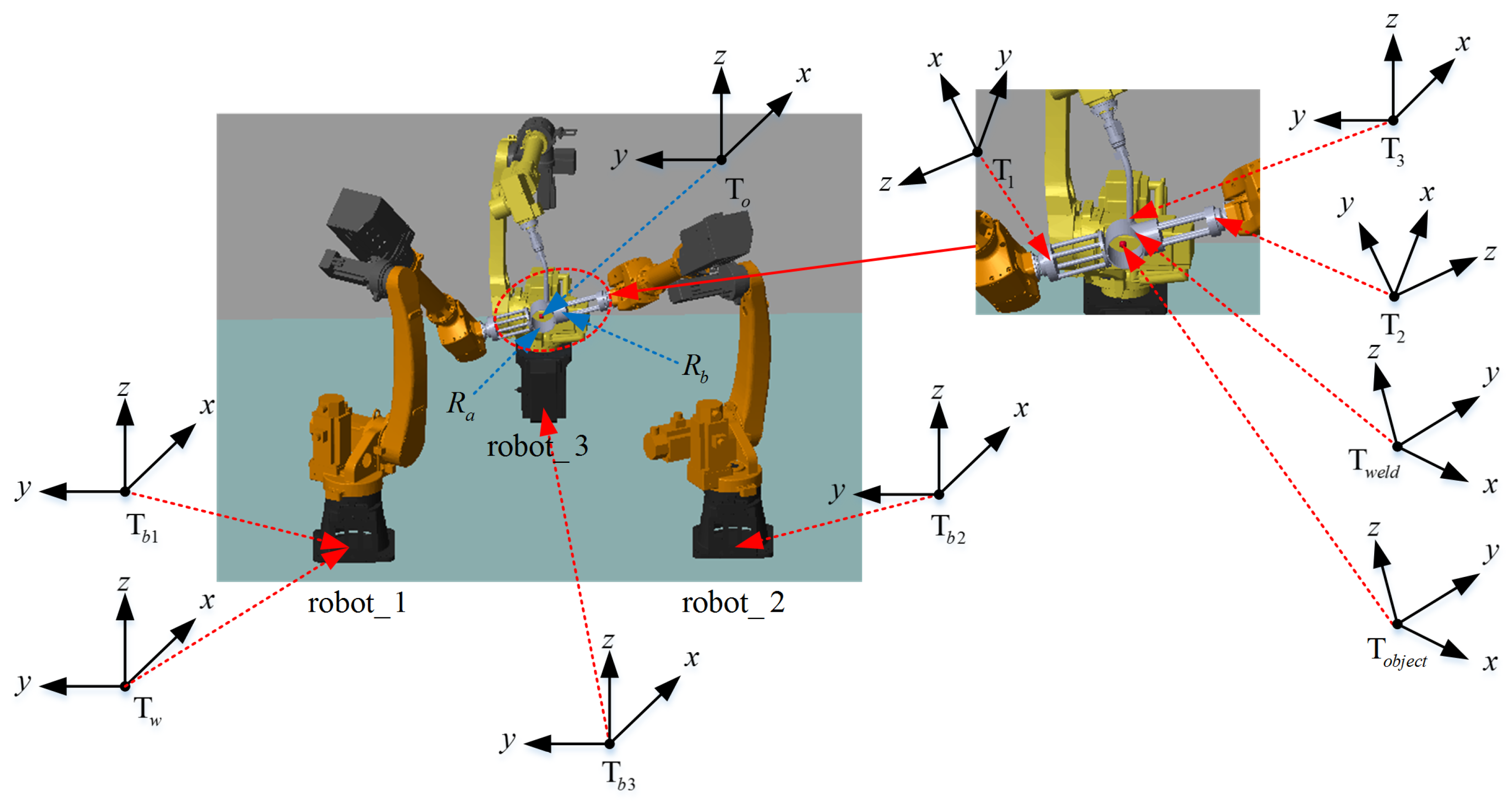
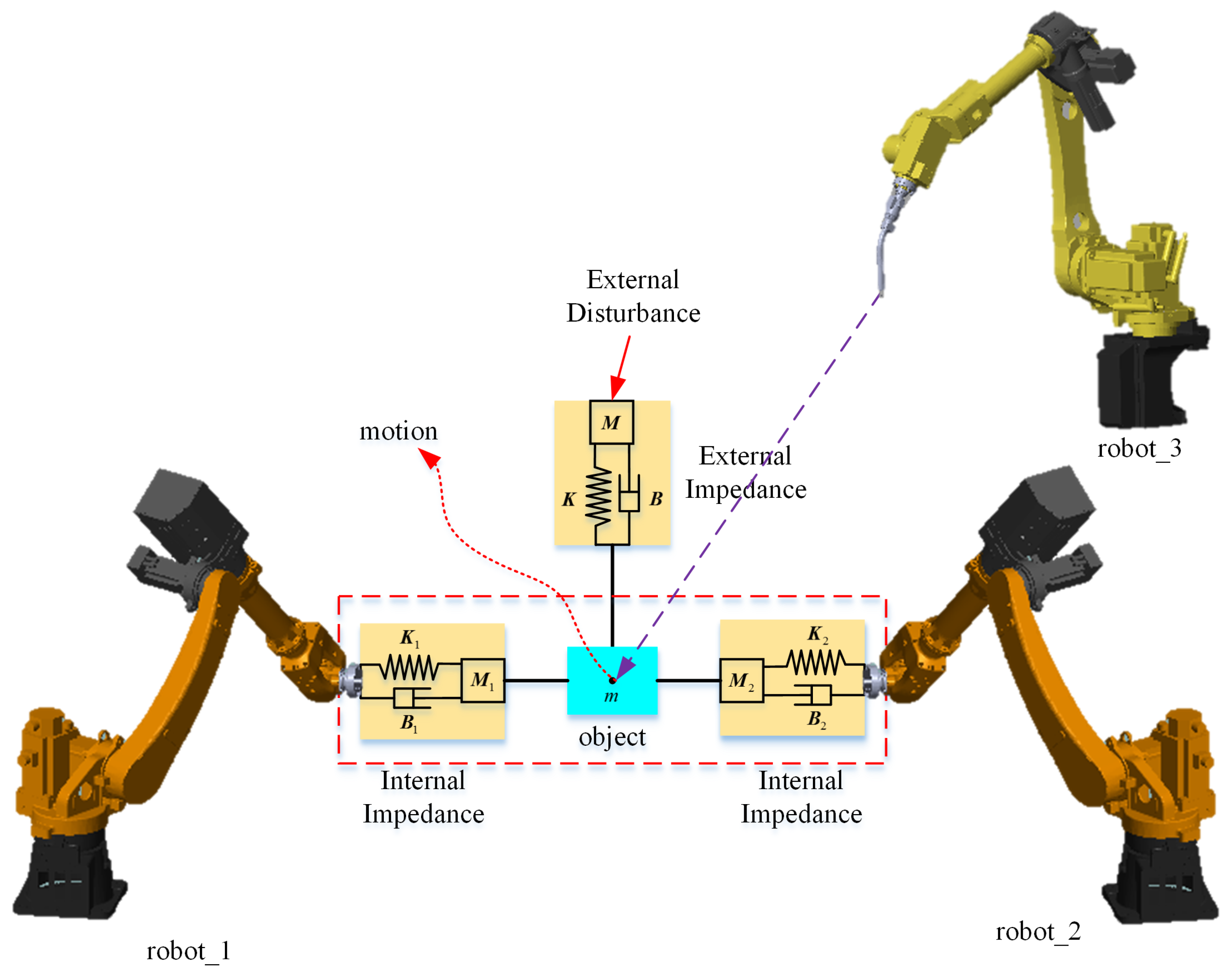
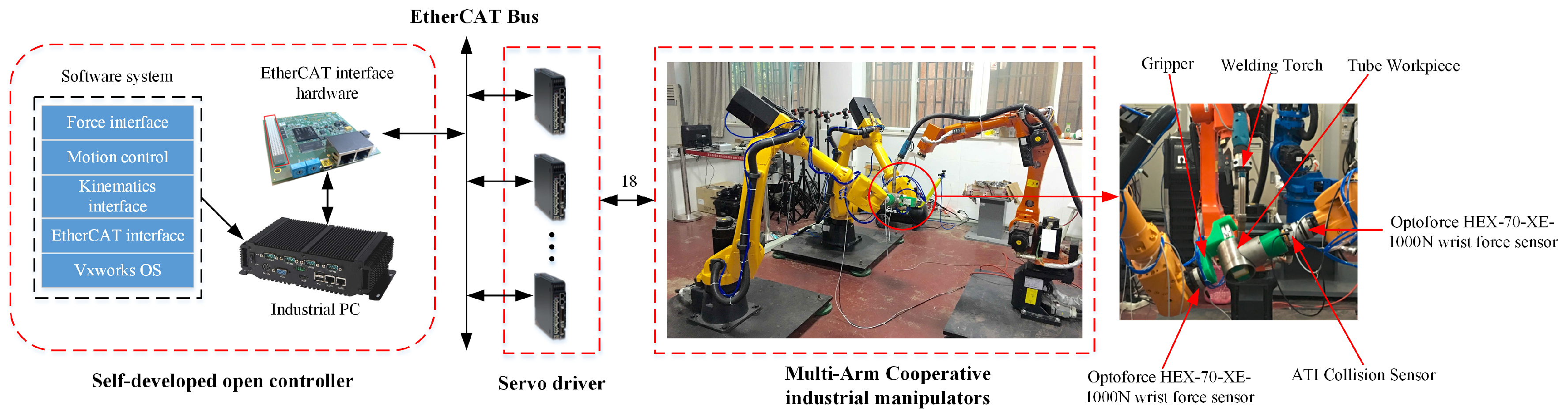
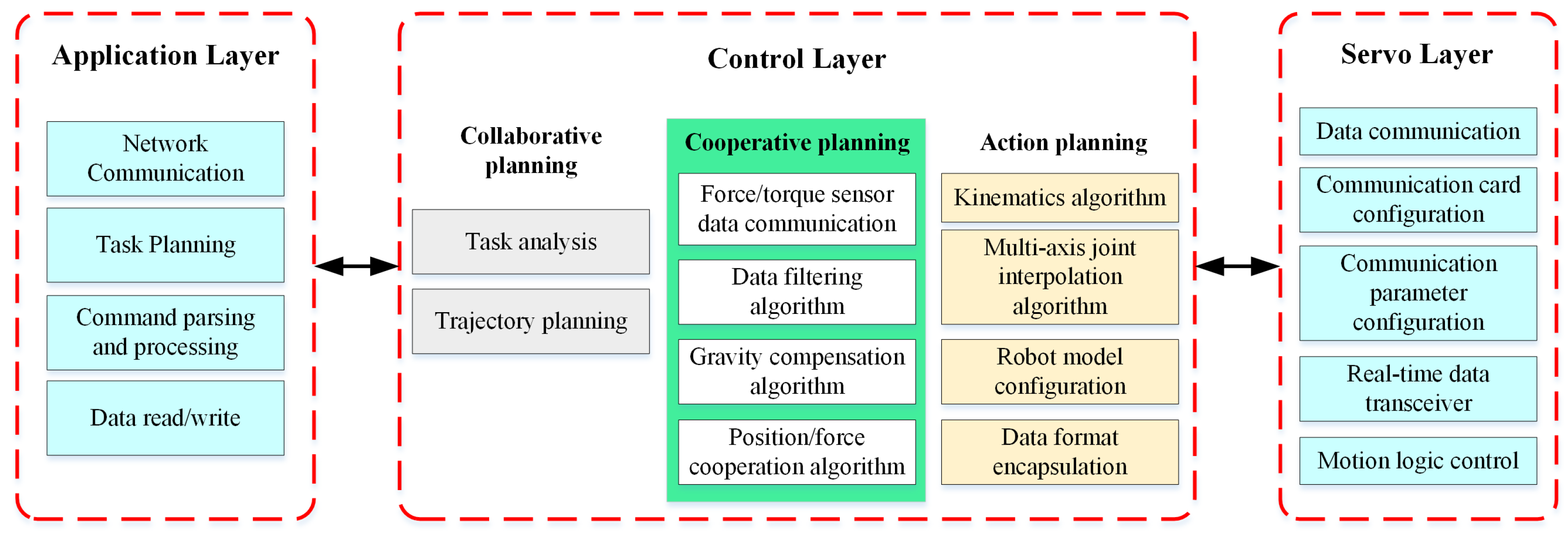
2.1. System Description

A multi-robot cooperative welding system refers to the collaboration of many sets of industrial robots on a welding task. In general, three or more robots are necessary. The cooperative system includes at least one welding robot, two or more robots are required which are used to splice the different pieces together. To discuss the key issue in welding process, the multi-robot systems cooperate welding a pipe-connect-pipe are given as an example in this paper. The typical multi-robot cooperation welding system schematic diagram is shown in Figure 1.
Figure 1 shows that the multi-robot welding system that includes three industrial robots, one welding robot, and two transfer robots. When the controller receives the specified task, two transfer robots grasp different welding workpieces, respectively in the initial welding position of relocating and splicing, at the same time, the welding robot begins to welding. After the two transfer robots cooperate with the workpiece, they will change the pose in the whole welding process, and then complete welding with the welding robot.

2.2. Problem Description

The multi-robot cooperative welding system is shown in Figure 1. To solve the constraint pose and wrench at the same time in welding process, it is difficulty to plan the cooperative motion trajectory and achieve the desired position/force cooperative effect during the transportation.
In order to satisfy the welding process requirements in the continuous welding process, the transfer robots must continuously change the posture of the clamping workpiece to ensure that the welding spot is always in the preset welding position. The welding robot must constantly adjust the position of the welding torch to ensure the welding torch meets the welding requirements. It is required that both the transfer robots and welding robot should satisfy a certain position and posture constraints during the whole welding process.
With the process of welding, the workpiece held by transfer robot is gradually welded, then the transfer robots and the workpiece will be formed as a closed-chain system. In the actual control system, the external disturbance and calibration errors are often existing. These disturbances and calibration errors will cause the time-varying trajectory deviations in the robot end-effector during cooperation, and the dynamic time-varying trajectory deviations can cause a huge internal forces between the robot and the workpiece. Improper control may lead a damage to the workpiece or robot.
From the above analysis, the two key issues in the control of multi-robot cooperative welding system are:
  • How to achieve the coordinated motion of multi-robot, which is the problem of planing the multi-robot trajectory;
  • How to effectively control the internal force between the robot and the workpiece, which is the problem of position/force cooperation.

3. Task-Oriented Multi-Robot Trajectory Planning

3.1. Problem Formulation

The schematic diagram of the multi-robot cooperating to complete the welding task is shown in Figure 2.
Where r o b o t _ 1 and r o b o t _ 2 are used for transfer robots, r o b o t _ 3 is used for a welding robot. The transfer robots grab the workpiece R a and R b , respectively. The welding robot is equipped with a welding torch at the end-effector, and the workpiece R a and R b are saddle-shaped after splicing.
The relevant coordinate system shown in Figure 2 is defined as follows. T w represents the world coordinated system, T o represents the reference coordinate system of the object. T b i denotes the base coordinate of the i-th robot, T i denotes the coordinate system of the i-th robot end-effector. T w e l d is the weld coordinate system of the workpiece, and T o b j e c t is the coordinate system of the workpiece. To facilitate the coordinate conversion, it is usually assumed that the world coordinate system coincides with the base coordinate system of r o b o t _ 1 .
The requirements for the multi-robot cooperation to complete the welding task of the tube include:
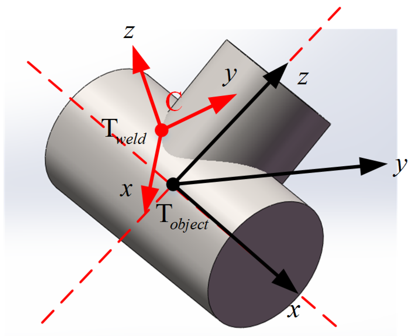
  • The welding torch should meet the requirements of the ship-type welding posture;
  • The configuration of each robot is reachable, and the configuration has no singularity in the welding process;
  • The motion planning results of each robot are in a common collaborative space;
  • There is no collision between the robot itself and another robots in the welding process.

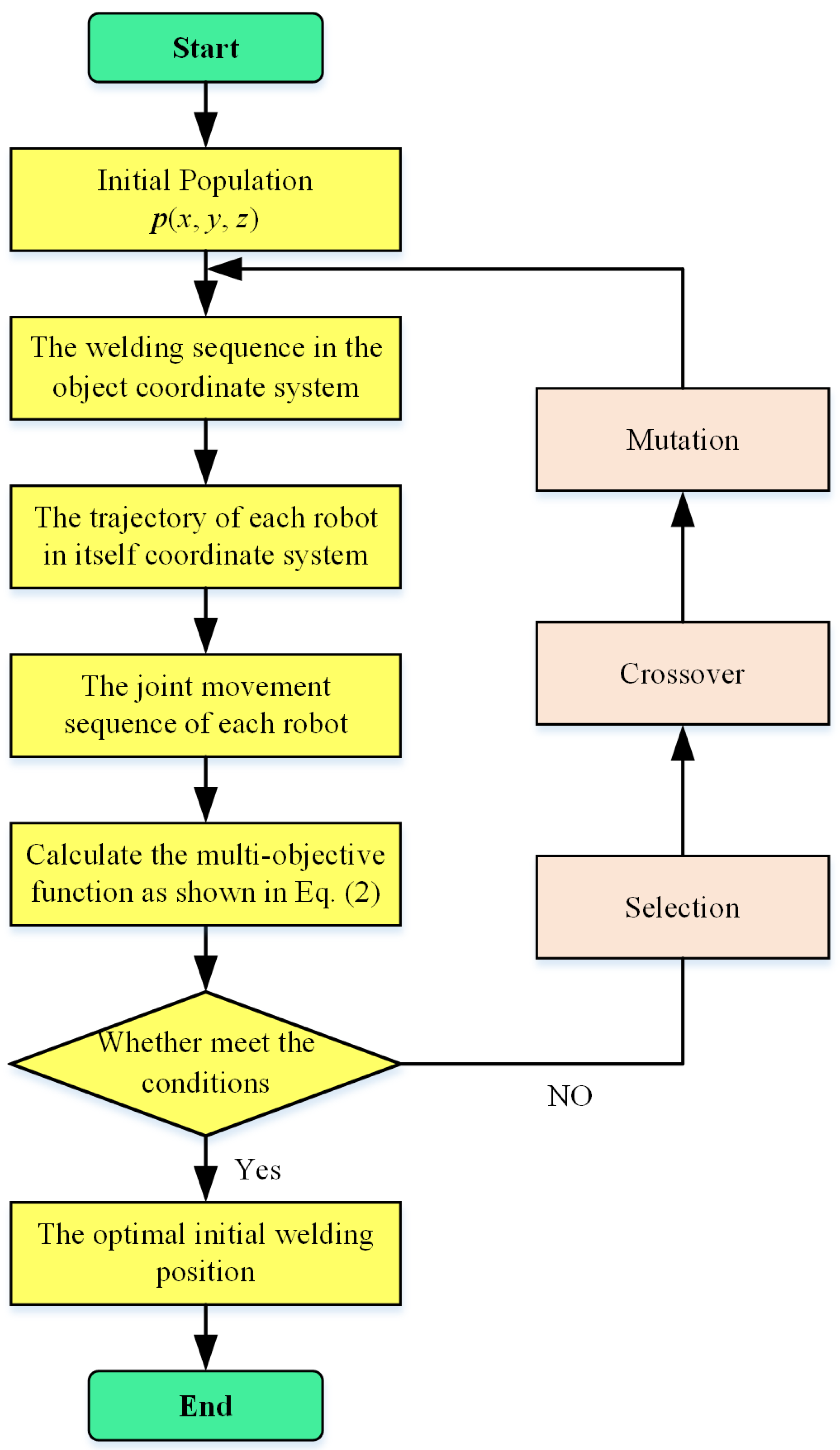
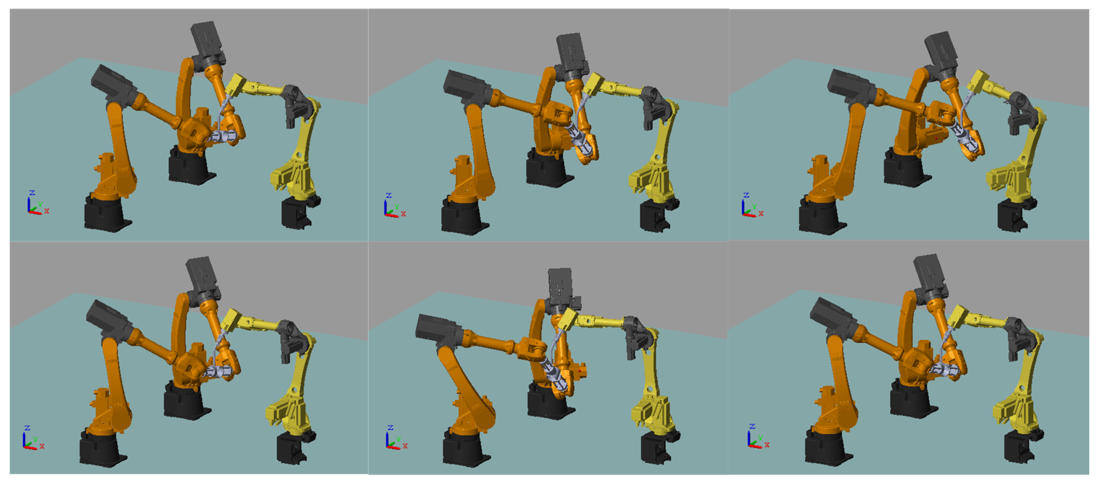
3.2. Trajectory Planning Strategy

As shown in Figure 2, the coordinate systems involved in the multi-robot cooperative welding process are numerous, and the transformation between coordinate systems is complicated. At the same time, the welding requirements as described above must also be met in order to finish the welding task smoothly. We can conduct that the initial welding position affects whether the entire welding task can proceed smoothly or not. Based on the above constraints and requirements, a multi-robot trajectory planning based on “hierarchical scheme”, which considered the optimal initial welding position, is proposed in this paper.
The basic idea of the above scheme is to first determine the optimal initial welding position, that is to determine the position of the reference coordinate system of the object in the world coordinate system. Then according to the welding task, the trajectory of the object in its reference coordinate system is planned. Finally, the robot end-effector trajectory is planned through the constraint relationship between the robot and the object.
The following steps are used to obtain the trajectory of multi-robot.
The first step is to determine the layout of the optimal welding position in the initial state, it is same to determine the position p (x,y,z) which T o is related to the world coordinate T w .
In combination with the requirements of the multi-robot cooperative welding process, the following indicators are considered to affect the layout selection of initial welding position.
  • The dual-arm task-based directional manipulability measure (DATBDMM) is mainly aimed at the transfer robots.
  • Flexible measure (FM) is mainly for the welding robot.
  • Global joint exercise (GJE) is used for the transfer robots and the welding robot.
According to the above performance indicators, the mathematical model for establishing the optimal initial welding position layout is shown in Equation (1).
DATBDM M c v = max p T J v c p - 1 FM = max m - 1 a n - 1 b D P ( α , β ) m - 1 a n - 1 b 1 GJE = min j = 1 3 i = 1 n j w i ( j θ i ( k ) - j θ i ( k - 1 ) ) 2 ,
where p R 3 × 1 represents the velocity unit vector at the point of mass center of the workpiece. J v c = J 1 c v J 1 c v T - 1 + J 2 c v J 2 c v T - 1 , J i c v represents the speed Jacobian matrix of the robot at the center of operated object. α , β indicate the rotation angle of welding torch around the y-axis and z-axis, respectively. After rotation, it can meet the welding requirements (shipping welding requirements). D P ( α , β ) denotes a pose reachable function. If there is an inverse solution, it is denoted as D P ( α , β ) = 1 . Otherwise, it is denoted as D P ( α , β ) = 0 . j w i represents the influence factor of each joint. j θ i ( k ) - j θ i ( k - 1 ) indicates the amount of joint change at a certain moment.
The optimal initial welding position p (x,y,z) is determined according to the above performance index, and the mathematical model of the optimal initial welding position for multi-robot cooperative welding is shown in Equation (2), then the optimal solution can be solved.
max f ( x , y , z ) = k d m · DATBDM M c v + k f m · FM k g j e · GJE ,
where f represents a multi-objective optimal function, k d m , k f m , k g j e represent the influence factors corresponding to the degree of dual-directional operation of the task, the flexibility, and the amount of joint change, respectively. According to the importance of each parameter and our preliminary experience, the value of k d m is set to 0.5, k f m is set to 0.3 and k g j e is set to 0.2.
In the second step, the trajectory of the operated object in the reference coordinate system is planned according to the welding task. The workpiece coordinate system which formed by the pipe connection is shown in Figure 3, the weld formed by the pipe is a saddle-shaped curve.
The principle of establishing the reference coordinate system of the operated object is, the intersection point of the pipe center-line is set as the origin of the coordinate system, the z-axis is along the center-line of the upper tube and the x-axis is along the center-line of the lower tube. In Figure 3, C is a point on the saddle-shaped curve, and the coordinate in the reference coordinate system of the operated object is C ( x , y , z ) . It can use the parametric equation to represent the equation of the saddle-shaped curve in the reference coordinate system as shown in Equation (3).
x = r · cos θ y = r · sin θ z = R 2 - r 2 · sin 2 θ ,
where r is the radius of the upper tube R b , R is the radius of the lower tube R a , and θ is the rotation angle parameter.
The solder point C can be adjusted to the ship-type welding posture by two-step, the weld coordinate system rotates α around the z o b j e c t , and rotates β around the x o b j e c t . Where β ( 0 , 2 π ) , α is the angle between z w e l d and the reference coordinate system z o of the operated object. The formula is shown in Equation (4).
α = cos - 1 R 2 - r 2 · sin 2 θ R · 2 + 2 · r R · sin 2 θ .
Based on the above analysis, the trajectory of the operated object in its reference coordinate system can be obtained as shown in Equation (5).
x = 0 y = 0 z = 0 R = f 2 π · i · t / T P = 0 Y = 2 π · i · t / T ,
where i denotes the i-th communication cycle, t denotes the total time which is required for the welding task, and T denotes the interpolation period. f ( · ) is a variable attitude function, it can be expressed as Equation (6).
f ( θ ) = cos - 1 R 2 - r 2 sin 2 θ R 2 + 2 r R sin 2 θ .
In the third step, the trajectory of each robot is planned according to the constraint relationship between the robot’s end-effector and the operated object. The movement of the operated object m (assumed coincident with the T o b j e c t ) in T o can be described as T m o ( t ) . T m o ( t ) is obtained according to the welding task (Equation (5)), and it can be expressed as Equation (7).
T m o ( t ) = R m o ( t ) p m o ( t ) 0 1 ,
where R m o ( t ) represents the ( 3 × 3 ) rotation matrix of the centroid with respect to the reference coordinate system of the operated object, and p m o ( t ) represents the ( 3 × 1 ) position matrix of the centroid with respect to the reference coordinate system of the operated object.
According to the closed-chain constraint formed by the transfer robot and the operated object, the pose constraint relationship of the following Equation (8) can be obtained.
T b i w · T i b i ( q i ) · T m i = T m w T o w · T m o ( t ) = T m w ,
where T b i w is homogeneous transform representing the robot base frame T b i with respect to the world frame T w . T i b i ( q i ) is homogeneous transform representing the end-effector frame of robot T i with respect to its base frame T b i . T m i is homogeneous transform representing the mass frame of object T m with respect to the end-effector frame of robot T i . T m w is homogeneous transform representing the mass frame of object T m with respect to the world frame T w . T o w is homogeneous transform representing the object frame T o with respect to the world frame T w .
From Equation (8), the kinematics of the i-th manipulator can be obtained as
T i b i ( q i ) = ( T b i w ) - 1 · T o w · T m o ( t ) · ( T m i ) - 1 = T w b i · T o w · T m o ( t ) · T i m ,
where T w b i , T o w and T i m are constant matrix.
In the entire cooperative welding task, the transfer robots coordinate the workpiece to meet the requirements of the ship-type welding. The welding robot doesn’t need to adjust the posture during the whole welding process, only the position of the welding torch in the operated object coordinate system needs to adjust. The position transformation matrix p 3 o of the tip of the welding torch which relative to the reference coordinate system of the operated object can be expressed as Equation (10).
p 3 o = r · cos α · cos β · cos θ - r · cos α · cos β · sin θ + sin α · R 2 - r 2 · sin 2 θ r · sin β · cos θ + r · cos α · cos θ - r · sin α · cos β · cos θ + r · sin α · sin β · sin θ + cos α · R 2 - r 2 · sin 2 θ .
According to the conversion relationship between the welding robot and the operated object, and the coordinate transform between the welding robot and the world coordinate system, Equation (11) can be obtained.
T b 3 w · T 3 b 3 ( q i ) = T 3 w T o w · T 3 o ( t ) = T 3 w
According to the Equation (11), the motion of the welding robot relative to its own coordinate system can be obtained as in Equation (12).
T 3 b 3 ( q i ) = T w b 3 · T o w · T 3 o ( t ) .
According to Equations (9) and (11), the trajectory of the transfer robot and the welding robot in their own coordinate system can be obtained. Based on the solution formula of inverse kinematics, the trajectory of each robot’s joint angles can be obtained.

4. Symmetrical Adaptive Variable Impedance Control for Multi-Robot Coordination

Multi-robot trajectory planning is the foundation for the cooperative welding process, because there is no generalized wrench constraint between the welding robot and the transfer robot, so the multi-robot position/force coordination control problems can be converted to the coordination between the transfer robots.

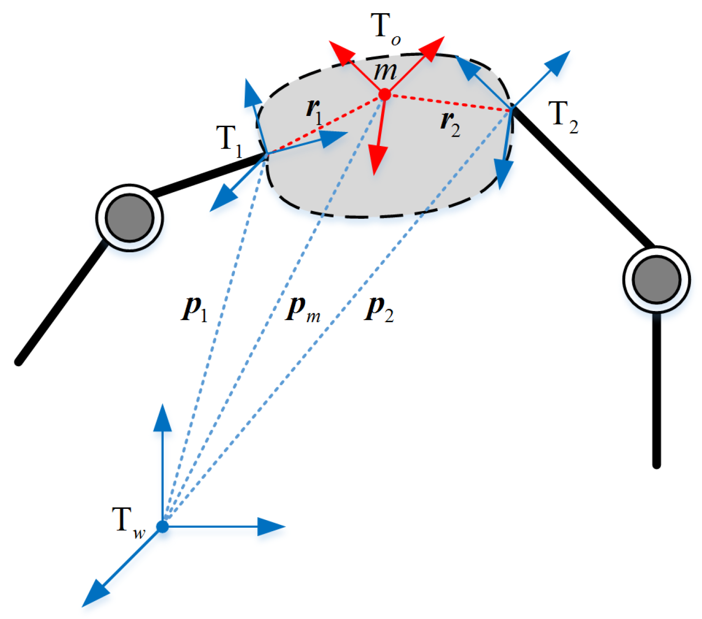
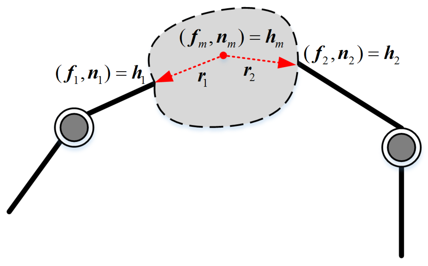
4.1. Problem Formulation

When the transfer robots are operating with a common object, the system becomes a closed-chain system. The closed-chain system which is constitute by the robots and the operated object is shown in Figure 4.
In Figure 4, p i ( i = 1 , 2 ) , p m denote the position vector of the robot end-effector with respect to the world coordinate system and the position vector of the operated object centroid with respect to the world coordinate system, respectively. r i ( i = 1 , 2 ) represents the position vector of the center of mass which is relative to the coordinate system of the robot. The movement of the operated object can be described by the center of mass m. And the Newton–Euler equation is shown as Equation (13).
f m = M c ¨ - M g n m = I ω ˙ + ω × I ω ,
where M and I are the mass and inertia matrices of the object, c and ω are the position and the angular velocity vector of the object, g is the acceleration of gravity, respectively.
If the movement of the operated object is known (as shown in Equation (5)). According to Equation (13), the wrench which the transfer robots need to exert on the center of operated object can be obtained. The wrench diagram of the force exerting on the operated object is shown in Figure 5.
The force formula of the transfer robots exerting on the operated object is shown in Equation (14).
f m = i = 1 2 f i n m = i = 1 2 n i + i = 1 2 r i × f i
where f i and n i represent the force and moment of the i-th robot end-effector exerting on the operated object, respectively.
According to the concept of “virtual chain”, Equation (13) can be expressed in the form of Equation (15).
h m = W h
where h m = f m n m , h = [ f 1 T , n 1 T , f 2 T , n 2 T ] T , W = I 3 0 3 I 3 0 3 S ( r 1 ) I 3 S ( r 2 ) I 3 , S ( r i ) = 0 - r i z r i y r i z 0 - r i x - r i y r i x 0 , r i = [ r i x r i y r i z ] T .
In Equation (15), W denotes the grip matrix and h denotes the wrench matrix which is exerting on the contact point of the operated object. If the wrench is known, the wrench which is exerting on the centroid point of the operated object can be obtained according to the Equation (15). But the actual situation is the inverse problem of Equation (15), it can be attributed to the load distribution problem.
From Equation (15), we can see that once the wrench h m at the center of the operated object is known, the wrench h which the transfer robots need to exert on the contact point can be obtained by solving the pseudo-inverse matrix. Since W is a row full rank matrix, theoretically there are infinitely many solutions for h . According to the conclusion in [20], the general form of the following equation is obtained.
h = W h m + ( I - W W ) ε ,
where W = A W T ( WA W T ) - 1 , A is a positive definite matrix and ε is an arbitrary vector.
According to the conclusion in [25], Equation (16) can be converted to the form of Equation (17).
h = W h m + V h i ,
where h i indicates the internal force at the center of mass of the operated object, which can be set according to the actual requirements. According to [26,27], W and V can be selected as shown in Equations (18) and (19), respectively.
W = 1 2 I 0 - S ( r 1 ) I I 0 S ( r 2 ) I ,
V = I 0 - S ( r 1 ) I - I 0 S ( r 2 ) - I .
In general, the external forces h m and the internal forces h i are given quantity. According to Equation (17), the wrench which needs to exert on the single robot can be obtained.
Although the resultant force of the transfer robots need to exert on the contact point of the object can be operated by the load distribution according to Equation (17). However, when there is the trajectory deviation existing which caused by external distribution or calibration error. The trajectory deviation will affect the motion of the operated object, but also affect the internal force between the transfer robots. If only the resultant force is simply tracked, not only the target trajectory can’t be tracked, but also failing to track the desired internal force.

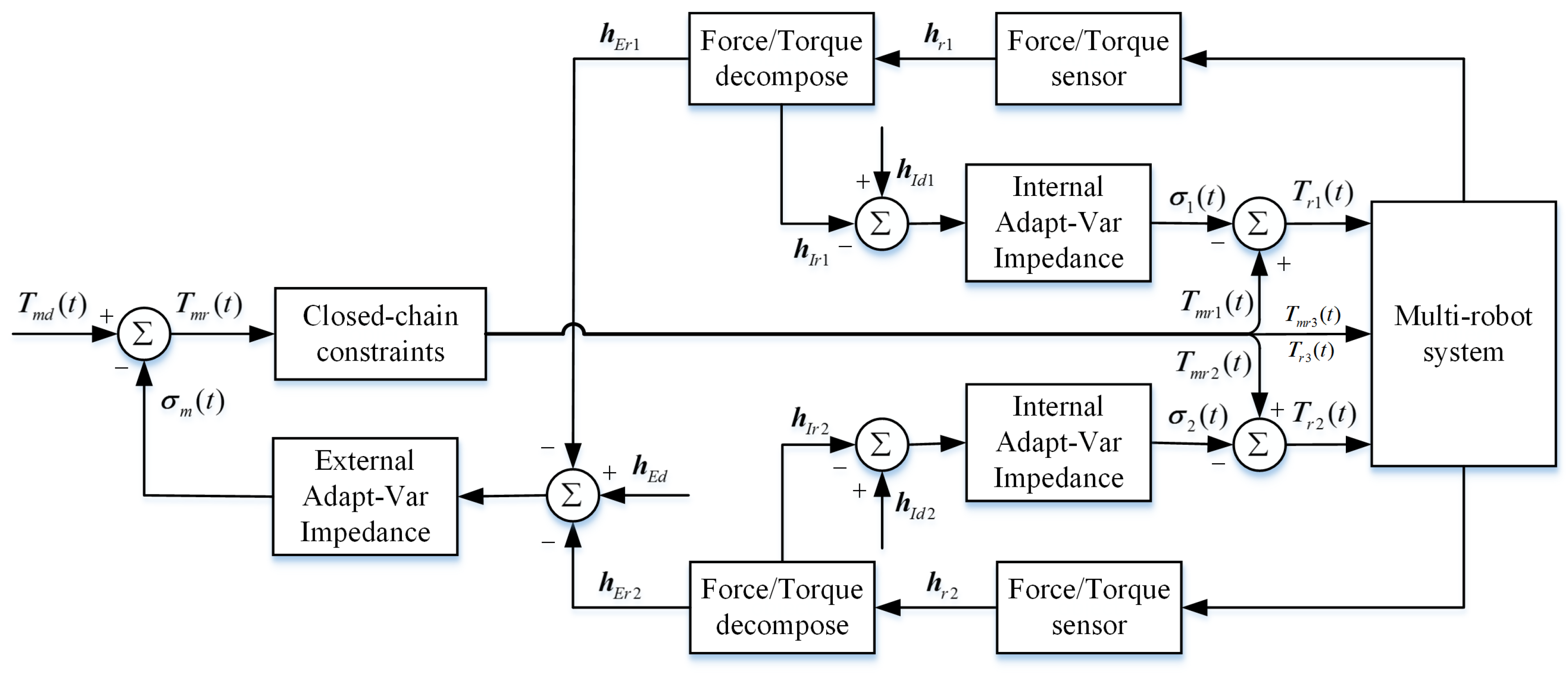
4.2. Symmetrical Adaptive Variable Impedance Control for Coordination Control

A symmetrical adaptive variable impedance position/force coordination strategy is proposed to solve the influence of the unknown trajectory deviation which is caused by the external disturbance forces. The basic idea is to first decompose the resultant forces into the internal and external force which are exerting on the contact points of the operated object. And ideally, the desired internal and external force can be obtained. Consider the disturbance force which is caused by the trajectory deviation is dynamically changing, so the adaptive variable impedance is proposed to track the desired position and force.
The first step is to decompose the internal and external force. The desired resultant force of the transfer robots need to exert on the contact point of the operated object is given as shown Equation (17). In order to achieve tracking the desired external force and internal force of the operated object by the transfer robots, Equation (17) can be expressed as a form of force exerting on the contact point of the operated object with transfer robots, it is shown as Equation (20).
h = h E + h I .
where h E and h I represent the external force and internal force exerting on the contact point of the operated object with the transfer robots, respectively. They are meet the following equation.
h E = W h m h I = V h i .
According to the Equation (21), the proposed internal and external force can be known.
In actual control, the wrench of the transfer robots exerting on the contact point of the operated object can be detected by a six-dimensional force/torque sensor which is installed at the end-effector of the robot, and the wrench can be denoted by h r . It is further possible to decompose h r into the external forces and internal forces as shown in Equation (22).
h E r = W W h r h I r = ( I - W W ) h r ,
where h E r and h I r represent the actual values of the external force and the internal force which are resolved based on the measured values by the six-dimensional force/torque sensor.
In the second step, position/force coordination control is based on symmetrical adaptive variable impedance. The schematic diagram of multi-robot position/force coordination control based on a symmetrical adaptive variable impedance is shown in Figure 6.
From Figure 6, a symmetric internal and external impedance coordination strategy is used for the transfer robots, and the position control strategy is used for the welding robot to just follow the object’s motion. For the transfer robots, the inner impedance controller is composed of transfer robots and the operated object, and the outer impedance controller is composed of the operated object and the environment (external disturbance or external force caused by trajectory deviations). In the actual control, a symmetrical coordination method is adopted to convert the internal and the external force which is exerted on the contact point of the operated object at the end-effector of the single robot. The purpose of the inner impedance controller is to track the desired internal force and modify the movement trajectory of the end of the transfer robot based on the force deviation. The purpose of the outer impedance controller is to track the desired external force and modify the movement trajectory of the operated object according to the force deviation. Then the transfer robots and welding robot update the respective movement trajectories according to the corrected trajectory of the operated object.
Considering that the desired internal forces, external forces, and the uncertain wrench which is caused by external disturbances are time-varying functions, an adaptive variable impedance control strategy is adopted. Therefore, the system is divided into an adaptive variable impedance inner loop controller and an adaptive variable impedance outer loop controller. The diagram of symmetrical internal and external adaptive impedance control is shown in Figure 7.
As shown in Figure 7, the desired movement trajectory of the operated object which inputs by the system is T m d ( t ) . In the ideal conditions, it exists T m d ( t ) = T m r ( t ) . According to the closed-chain constraint conditions, the trajectories ( T m r 1 ( t ) , T m r 2 ( t ) , T m r 3 ( t ) ) of multi-robot can be obtained, where T m r 1 ( t ) = T r 1 ( t ) , T m r 2 ( t ) = T r 2 ( t ) , T m r 3 ( t ) = T r 3 ( t ) . When uncertainty forces caused by the trajectory deviations exist, they can be obtained by the two six-dimensional force/torque sensor which are denoted by h r 1 and h r 2 . According to Equation (22), the measurement of the resultant forces can be decomposed into external forces( h E r 1 , h E r 2 ) and internal forces( h I r 1 , h I r 2 ), respectively.
When there is a force deviation between the measured external force and the desired external force h E d , the system will obtains an error trajectory σ m ( t ) through the adaptive variable impedance external loop controller, then the corrected trajectory T m r ( t ) of the operated object is obtained, and the trajectory of each robot is further corrected. When there is a force deviation between the measured internal force and the desired internal force ( h I d 1 and h I d 2 ), the system obtains error trajectories ( σ 1 ( t ) and σ 2 ( t ) ) through the adaptive variable impedance inner loop controller, and then transfer robots’s correction trajectories ( T r 1 ( t ) and T r 1 ( t ) ) can be obtained.
The adaptive variable external impedance law is proposed as Equation (23), as shown in Figure 7.
M [ T ¨ m r ( t ) - T ¨ m d ( t ) ] + [ B + Δ B ( t ) ] [ T ˙ m r ( t ) - T ˙ m d ( t ) ] = h E r 1 ( t ) + h E r 2 ( t ) - h E d ( t ) Δ B ( t ) = B T ˙ m r ( t ) - T ˙ m d ( t ) Φ ( t ) Φ ( t ) = Φ ( t - λ ) + σ h E d ( t - λ ) - h E r 1 ( t - λ ) - h E r 2 ( t - λ ) B
M I [ T ¨ r i ( t ) - T ¨ m r i ( t ) ] + [ B I + Δ B I ( t ) ] [ T ˙ r i ( t ) - T ˙ m r i ( t ) ] = h I r i ( t ) - h I d i ( t ) Δ B I ( t ) = B I T ˙ r i ( t ) - T ˙ m r i ( t ) Φ ( t ) Φ ( t ) = Φ ( t - λ ) + σ h I d i ( t ) - h I r i ( t ) B I
where M is the desired inertia matrix, B is the damping matrix, λ is the sampling period of the controller and σ is the update rate.
The adaptive variable internal impedance law showns in Equation (Figure 7) is expressed as Equation (24).
Where M I denotes the desired inertia matrix of the internal wrench, B I denotes the damping matrix of the internal wrench, and i denotes i- t h robot.
In our previous work [28], the adaptive variable impedance control has been proven stable and convergent and been used to track the dynamic force with unknown trajectory deviations.

5. Simulations and Experiments
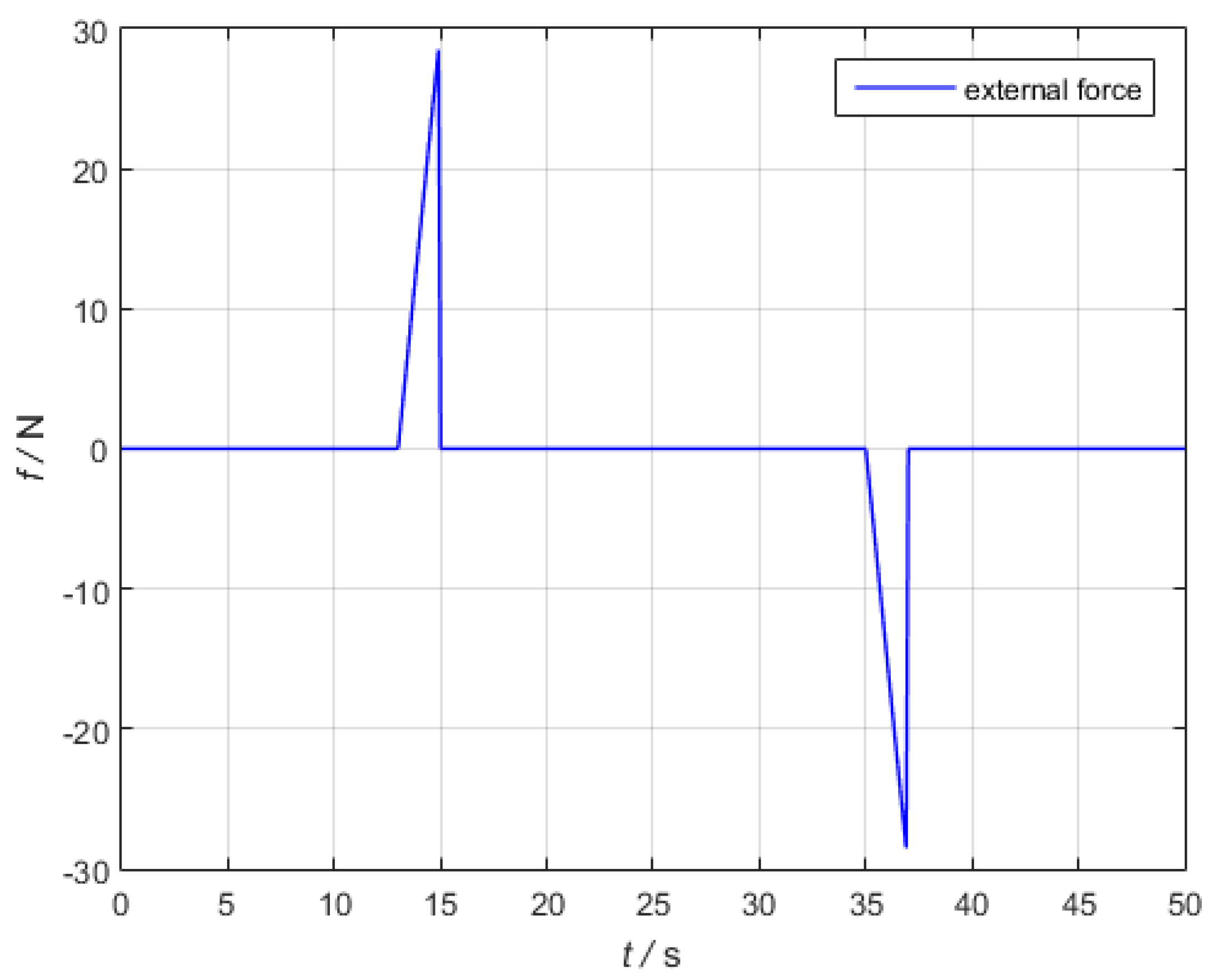
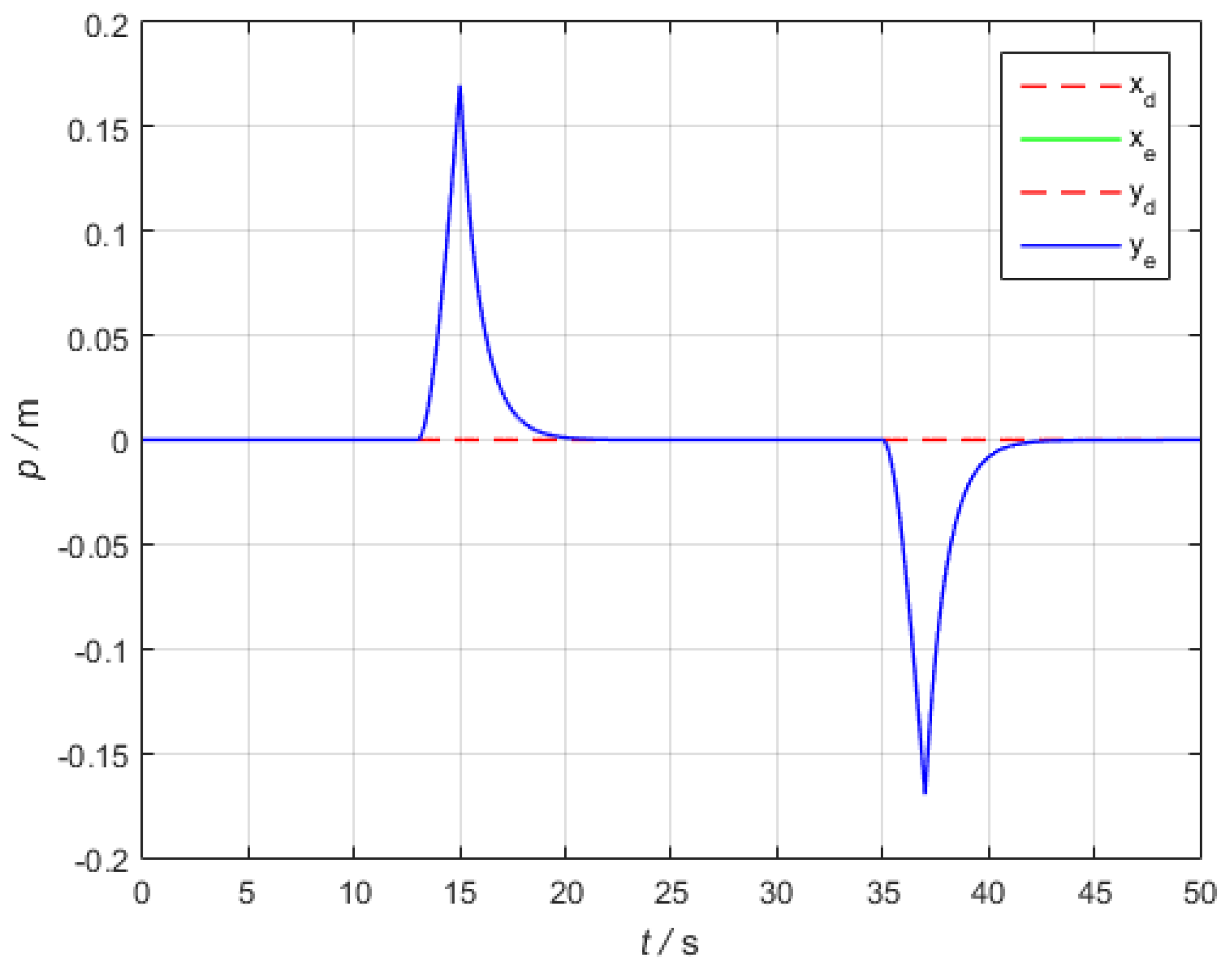
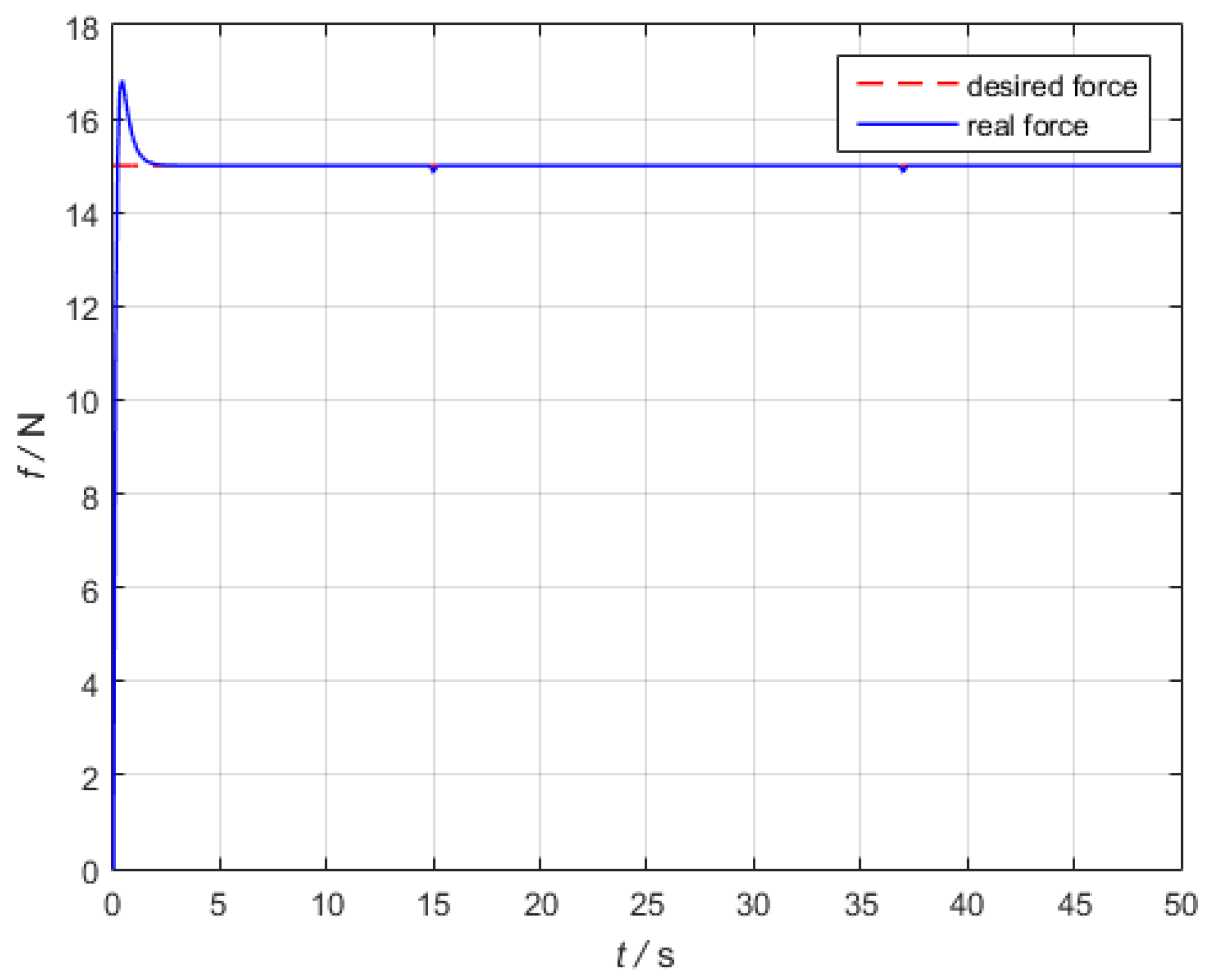
5.1. Simulation

This section mainly verifies the feasibility of position/force coordination for multi-robot based on the symmetrical adaptive variable impedance control. Matlab SimMechanics was used to simulate the multi-robot cooperative welding. In order to verify the effectiveness of the algorithm, the simulation is close to the actual physical experiment. During the experiment, it is assumed that there is a certain expected pressure and external disturbances, the purpose is to test the tracking effect of external and internal forces.
The object is composed into two rigid pipes, R a and R b , respectively. The radius r a = 0.051 m , r b = 0.0445 m , the length l a = 0.12 m , l b = 0.08 m , respectively. The thickness of the pipe is h = 0.003 m, and the density is 1000 kg / m 3 . The center of the 1st robot’s end-effector and the center of pipe R a coincide the center of the 2nd robot’s end-effector and the centerline of pipe R b is coincide.
The optimal initial welding position [0.5 m −0.75 m 0.404 m] can be obtained by solving Equation (2) through genetic algorithm, the optimization process of genetic algorithm is shown in Figure 8. According to the requirements of the welding task, the variable pose trajectory of the operated object is shown as Equations (5) and (6). Furthermore, the motion of each robot with respect to its respective base coordinate system can be solved according to Equations (9) and (12). Assuming that the desired internal wrench is [0 N 0 N 15 N 0 N·m 0 N·m 0 N·m], the desired internal force is among z-axis. The external disturbance is operated among x and y axis are shown in Figure 9.
The schematic diagram of the system simulation process for multi-robot completing pipe welding is shown in Figure 10.
The desired motion trajectory of the operated object and the actual motion trajectory after the external disturbance in x-axis and y-axis are shown in Figure 11, and the internal force tracking effect of the transfer robots is shown in Figure 12.
Combining Figure 11 and Figure 12, it shows that after the external disturbance exerting on the x and y axis, the closed-chain system is flexible. From Figure 12, it shows that during the coordinated welding process, the tracking of the desired internal force can be achieved, and the internal force is maintained within the allowable tolerance range throughout the entire process.

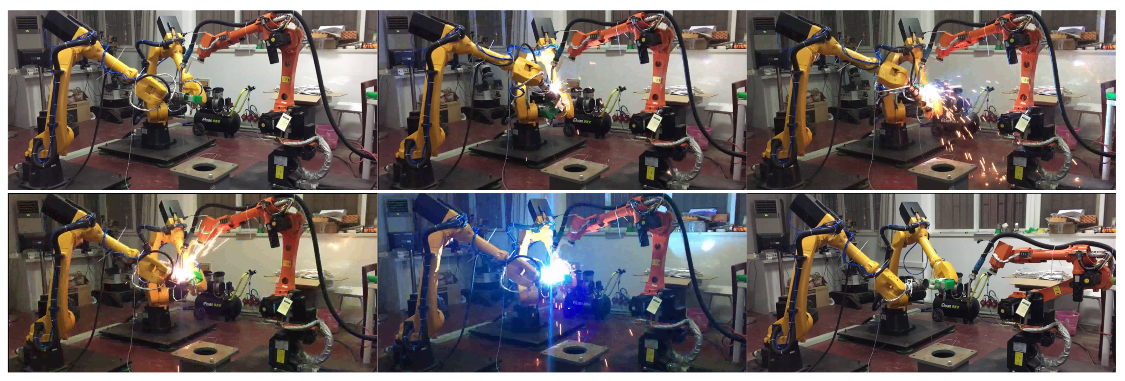
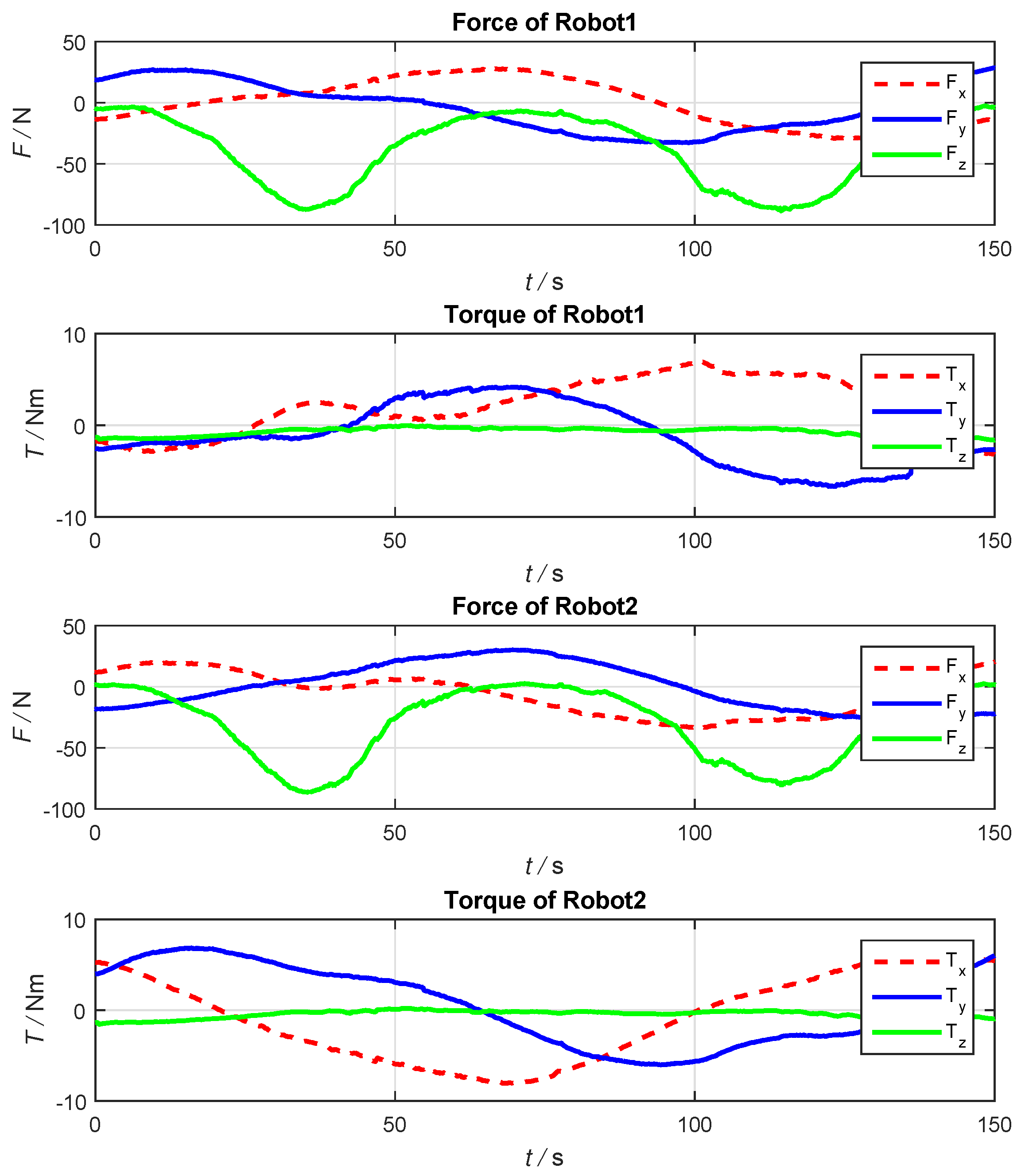
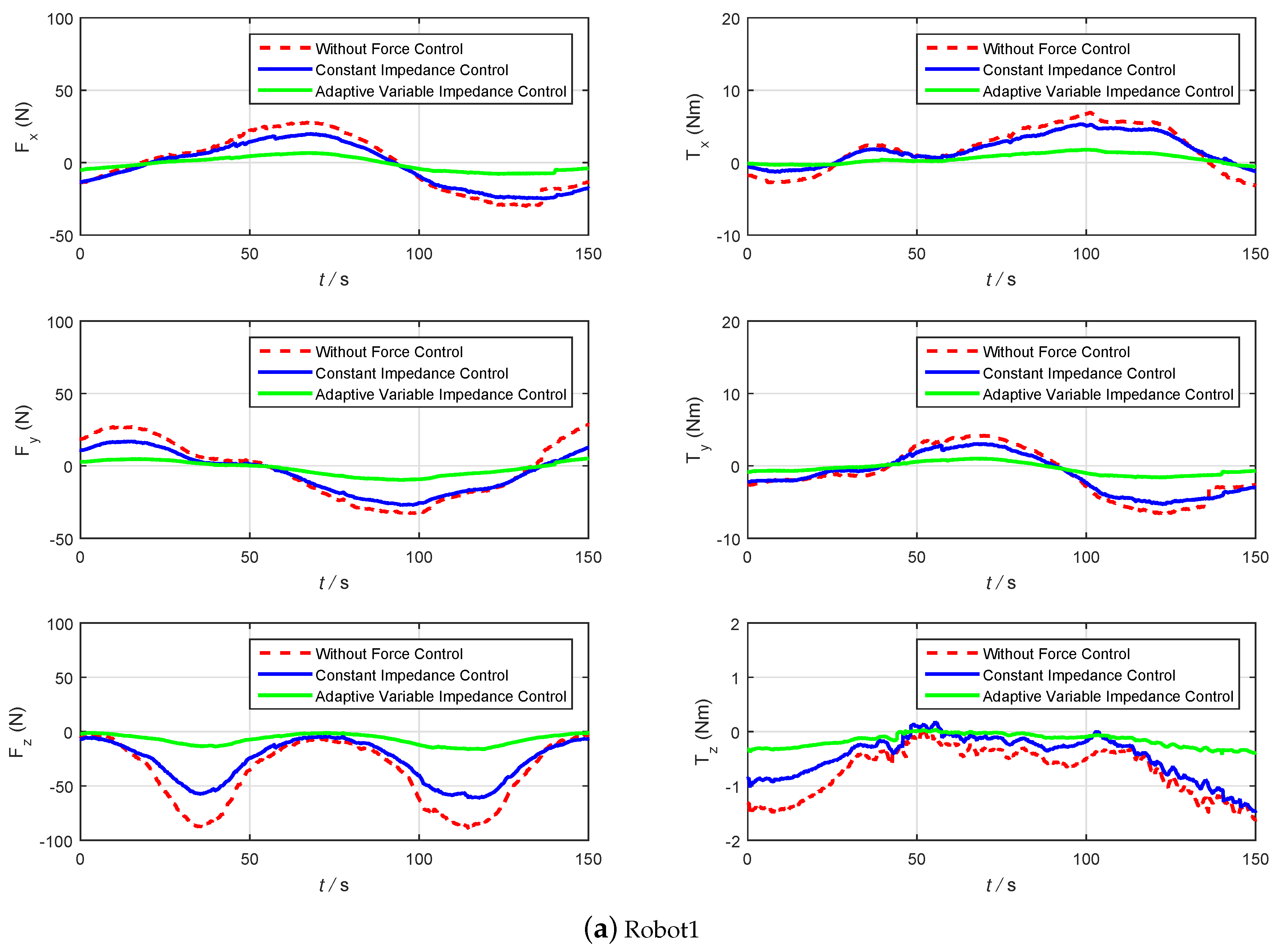
5.2. Experimental Studies

To demonstrate the performance of the proposed algorithm, experiments were conducted using the test-bed as shown in Figure 13. And the logical scheme of the control software is shown in Figure 14.
The test platform consisted of aself-developed open controller, servo drivers, two ESTUN ER16 industrial manipulators, one ESTUN ER4 industrial manipulators, two force/torque sensors, a collision sensor, and two pairs of gripper. The self-developed open controller used an industrial PC with a configuration of Intel Celeron @1.2 GHz, 512 MB of RAM, VxWorks RTOS. The servo drivers used ESTUN ProNet series, the bandwidth of the servo driver is from 125 Hz to 1000 Hz. Hischer CIFX communication card is used to EtherCAT communication between industrial PC and servo drivers. The force/torque sensors use Optoforce HEX-70-XE-1000N, the collision sensor uses ATI SR-61. The self-developed open controller was used for task coordination, position/force control, motion planning, forward/inverse kinematics, 18-axis cycle synchronization interpolation and human-machine interface. The force/torque sensor was mounted at the wrist of each manipulator. An ATI collision sensor was installed between the end-effector and the gripper of the 1- s t robot was added for the protection of the whole system. The force/torque sensor provided the UDP protocol with the fastest frequency of 1 kHz, so the force sensor and the controller communicate through UDP. Consider the controller computing power, the bandwidth of the servo drivers and communication frequency of the force sensor at the same time, the communication cycles of the controller and the servo drivers, the controller and the force sensor are both set to 5 ms. Two force sensors were initialized by gravity compensation.
The physics experiment was consistent with the simulation. The transfer robots separately grasp a part of the workpiece to be welded, which was spliced at the initial welding point. The welding robot started arcing at the initial welding point. Then the transfer robots coordinated the workpiece to be displace, and the welding robot completed the welding of the weld seam. The key frames of the whole welding task is shown in Figure 15.
During the welding process, due to the presence of unknown factors such as mechanical calibration error, base coordinate calibration error, and external disturbance, the transfer robots produced an uncertain wrench to the welding workpiece. The internal wrench exerting on the end-effector without force control is shown in Figure 16.
From the above results, we can see that the internal wrench without the force control is large. In order to control the internal forces in a proper range, a symmetrical adaptive variable impedance control is proposed in this paper. To certify the performance of the proposed algorithm, the traditional constant impedance control and the proposed algorithm are compared as shown in Figure 17.
Figure 17 shows that the force control effect has been significantly improved. The desired trajectory of transfer robots’ end-effector and the center of workpiece are shown in Figure 18.
From Figure 17, we can conclude that the variable adaptive impedance control can achieve a better effect than the traditional constant impedance control. By using the proposed algorithm, the trajectory deviations of the transfer robots are shown in Figure 19, the trajectory deviations of the welding robot is shown in Figure 20.
Through Figure 17, Figure 18, Figure 19 and Figure 20, it shows that the internal force of the transfer robots exerting on the workpiece to be welded is within the controllable range and does not cause damage to the welding system. The welding result has been shown in Figure 21. It indicates that a uniform smooth weld seam without cracks has been got by our method. And the welding quality is much better compared with novice welders.
In the simulations and experiments, the selection method of the design parameters of the control system ( M , B , λ and σ ) can be referenced in [28]. The following parameters can obtain the good performance in the above simulations and experiments, the inertia coefficient M = d i a g { 1 , 1 , 1 , 0 , 0 , 0 } , M I = d i a g { 1 , 1 , 1 , 0 , 0 , 0 } , the initial damping coefficient B = d i a g { 65 , 65 , 65 , 0 , 0 , 0 } , B I = d i a g { 90 , 90 , 90 , 0 , 0 , 0 } , λ = 0.005 s and σ = 0.01 .

6. Conclusions

In the actual multi-robot cooperative welding system, the trajectory planning and position/force coordination control are the two most critical issues. The trajectory planning is the basis of position/force coordination control. The biggest difference between multi-robot cooperative welding and other types of multi-robot cooperative tasks is that they have more constraints and the coordinate system is more cumbersome and complicated. During the welding of the workpiece, an unknown changing wrench can be generated between the transfer robots and the workpiece due to the external disturbance and calibration errors.
In the face of problems such as complex changes of coordinate system and welding constraints in the process of multi-robot cooperative welding, a planning strategy for “hierarchical planning” is proposed in this paper. Firstly, the optimal initial welding position is determined according to the optimization index, and then the trajectory of the operated object in its coordinate system is planned. Finally, the trajectory of each robot relative to its base coordinate system is obtained.
In actual control systems, due to the calibration errors and external disturbances, the trajectory of robot end-effector is often deviated. In response to this problem, a symmetric adaptive internal and external variable impedance control strategy is used to track the internal and external forces exerting on the operated object. Through simulation and physical tests, it is concluded that the proposed control strategy is applicable to multi-robot cooperative welding systems and can effectively solve the two problems in the process of cooperative welding.

Author Contributions

Methodology, Y.G., J.D.; validation and data curation, M.C., J.D.; writing—original draft preparation, Y.G., J.D.; writing—review and editing, Y.G.; visualization, M.C.; supervision, Y.G.; project administration, X.D.; funding acquisition, Y.G., X.D.

Funding

This research was funded by National Natural Science Foundation of China under grant number 61873308, 61503076, 61175113 and Natural Science Foundation of Jiangsu Province under grant number BK20150624.

Conflicts of Interest

The authors declare no conflict of interest.

References

  1. Mason, M.T. Compliance and Force Control for Computer Controlled Manipulators. IEEE Trans. Syst. Man Cybern. 1981, 11, 418–432. [Google Scholar] [CrossRef] [Green Version]
  2. Zheng, Y.F.; Luh, J.Y.S. Control of two coordinated robots in motion. In Proceedings of the 1985 24th IEEE Conference on Decision and Control, Fort Lauderdale, FL, USA, 11–13 December 1985; pp. 1761–1766. [Google Scholar]
  3. Luh, J.Y.S.; Zheng, Y.F. Constrained Relations between Two Coordinated Industrial Robots for Motion Control. Int. J. Robot. Res. 1987, 6, 60–70. [Google Scholar] [CrossRef]
  4. Nagai, K.; Iwasa, S.; Watanabe, K.; Hanafusa, H. Cooperative control of dual-arm robots for reasonable motion distribution. In Proceedings of the 1995 IEEE/RSJ International Conference on Intelligent Robots and Systems. Human Robot Interaction and Cooperative Robots, Pittsburgh, PA, USA, 5–9 August 1995; p. 54. [Google Scholar]
  5. Zhou, B.; Xu, L.; Meng, Z.; Dai, X. Kinematic cooperated welding trajectory planning for master-slave multi-robot systems. In Proceedings of the 2016 35th Control Conference, Chengdu, China, 27–29 July 2016; pp. 6369–6374. [Google Scholar]
  6. Mcclamroch, N.H.; Wang, D. Feedback stabilization and tracking of constrained robots. IEEE Trans. Autom. Control 1988, 33, 419–426. [Google Scholar] [CrossRef]
  7. Krishnan, H.; Mcclamroch, N.H. Tracking in Nonlinear Differential-Algebraic Control Systems with Applications to Constrained Robot Systems; Pergamon Press, Inc.: Oxford, UK, 1994. [Google Scholar]
  8. Nakano, E. Cooperational Control of the Anthropomorphous Manipulator “MELARM”. In Proceedings of the 4th International Symposium on Industrial Robots, Tokyo, Japan, 19–21 November 1974; pp. 251–260. [Google Scholar]
  9. Barbieri, L.; Bruno, F.; Gallo, A.; Muzzupappa, M.; Russo, M.L. Design, prototyping and testing of a modular small-sized underwater robotic arm controlled through a Master-Slave approach. Ocean Eng. 2018, 158, 253–262. [Google Scholar] [CrossRef]
  10. Scaradozzi, D.; Sorbi, L.; Zingaretti, S.; Biagiola, M.; Omerdic, E. Development and integration of a novel IP66 Force Feedback Joystick for offshore operations. In Proceedings of the 22nd Mediterranean Conference on Control and Automation, Palermo, Italy, 16–19 June 2014; pp. 664–669. [Google Scholar]
  11. Hayati, S. Hybrid position/Force control of multi-arm cooperating robots. In Proceedings of the 1986 IEEE International Conference on Robotics and Automation, San Francisco, CA, USA, 7–10 April 1986; pp. 82–89. [Google Scholar]
  12. Uchiyama, M.; Iwasawa, N.; Hakomori, K. Hybrid position/Force control for coordination of a two-arm robo. In Proceedings of the 1987 IEEE International Conference on Robotics and Automation, Raleigh, NC, USA, 31 March–3 April 1987; pp. 1242–1247. [Google Scholar]
  13. Uchiyama, M.; Dauchez, P. A symmetric hybrid position/force control scheme for the coordination of two robots. In Proceedings of the 1988 IEEE International Conference on Robotics and Automation, Philadelphia, PA, USA, 24–29 April 1988; Volume 1, pp. 350–356. [Google Scholar]
  14. Masaru, U.; Pierre, D. Symmetric kinematic formulation and non-master/slave coordinated control of two-arm robots. Adv. Robot. 1992, 7, 361–383. [Google Scholar]
  15. Sun, D.; Mills, J.K. Adaptive synchronized control for coordination of multirobot assembly tasks. IEEE Trans. Robot. Autom. 2002, 18, 498–510. [Google Scholar]
  16. Rodriguez-Angeles, A.; Nijmeijer, H. Mutual synchronization of robots via estimated state feedback: A cooperative approach. IEEE Trans. Control Syst. Technol. 2004, 12, 542–554. [Google Scholar] [CrossRef]
  17. Lian, K.Y.; Chiu, C.S.; Liu, P. Semi-decentralized adaptive fuzzy control for cooperative multirobot systems with H-inf motion/internal force tracking performance. IEEE Trans. Syst. Man Cybern. Part B Cybern. 2002, 32, 269–280. [Google Scholar] [CrossRef] [PubMed]
  18. Gueaieb, W.; Karray, F.; Al-Sharhan, S. A robust adaptive fuzzy position/force control scheme for cooperative manipulators. IEEE Trans. Control Syst. Technol. 2003, 11, 516–528. [Google Scholar] [CrossRef]
  19. Gueaieb, W.; Karray, F.; Al-Sharhan, S. A Robust Hybrid Intelligent Position/Force Control Scheme for Cooperative Manipulators. IEEE/ASME Trans. Mechatron. 2007, 12, 109–125. [Google Scholar] [CrossRef]
  20. Walker, I.D.; Freeman, R.A.; Marcus, S.I. Analysis of Motion and Internal Loading of Objects Grasped by Multiple Cooperating Manipulators. Int. J. Robot. Res. 1991, 10, 396–409. [Google Scholar] [CrossRef]
  21. Bonitz, R.G.; Hsia, T.C. Force decomposition in cooperating manipulators using the theory of metric spaces and generalized inverses. In Proceedings of the 1994 IEEE International Conference on Robotics and Automation, San Diego, CA, USA, 8–13 May 1994; Volume 2, pp. 1521–1527. [Google Scholar]
  22. Leidner, D.; Dietrich, A.; Schmidt, F.; Borst, C.; Albu-Schäffer, A. Object-centered hybrid reasoning for whole-body mobile manipulation. In Proceedings of the IEEE International Conference on Robotics and Automation, Hong Kong, China, 31 May–7 June 2014; pp. 1828–1835. [Google Scholar]
  23. Dietrich, A.; Wimbock, T.; Albu-Schaffer, A. Dynamic whole-body mobile manipulation with a torque controlled humanoid robot via impedance control laws. In Proceedings of the IEEE/RSJ International Conference on Intelligent Robots and Systems, San Francisco, CA, USA, 25–30 September 2011; pp. 3199–3206. [Google Scholar]
  24. Ott, C.; Hirzinger, G. Comparison of object-level grasp controllers for dynamic dexterous manipulation. Int. J. Robot. Res. 2012, 31, 3–23. [Google Scholar]
  25. Caccavale, F.; Chiacchio, P.; Marino, A.; Villani, L. Six-DOF Impedance Control of Dual-Arm Cooperative Manipulators. IEEE/ASME Trans. Mechatron. 2008, 13, 576–586. [Google Scholar] [CrossRef]
  26. Chiacchio, P.; Chiaverini, S.; Sciavicco, L.; Siciliano, B. Global task space manipulability ellipsoids for multiple-arm systems. IEEE Trans. Robot. Autom. 1991, 7, 678–685. [Google Scholar] [CrossRef]
  27. Erhart, S.; Hirche, S. Internal Force Analysis and Load Distribution for Cooperative Multi-Robot Manipulation. IEEE Trans. Robot. 2017, 31, 1238–1243. [Google Scholar] [CrossRef]
  28. Duan, J.; Gan, Y.; Chen, M.; Dai, X. Adaptive variable impedance control for dynamic contact force tracking in uncertain environment. Robot. Auton. Syst. 2018, 102, 54–65. [Google Scholar] [CrossRef]
Figure 1. The diagram of multi-robot cooperation welding system.
Applsci 09 00924 g001
Figure 2. The system coordinates of multi-robot pipe-connect-pipe welding task.
Applsci 09 00924 g002
Figure 3. The schematic diagram of the object coordinate system and welding coordinate system.
Applsci 09 00924 g003
Figure 4. The diagram of the closed-chain system.
Applsci 09 00924 g004
Figure 5. The wrench diagram of force exerting on the operated object.
Applsci 09 00924 g005
Figure 6. The schematic diagram of multi-robot position/force coordination control.
Applsci 09 00924 g006
Figure 7. The diagram of symmetrical internal and external adaptive impedance control.
Applsci 09 00924 g007
Figure 8. The optimization process of genetic algorithm.
Applsci 09 00924 g008
Figure 9. The external disturbance exerting on the operated object.
Applsci 09 00924 g009
Figure 10. The schematic diagram of the system simulation process for multi-robot systems.
Applsci 09 00924 g010
Figure 11. The simulation result of desired trajectory and actual trajectory.
Applsci 09 00924 g011
Figure 12. The simulation result of the internal force tracking effect.
Applsci 09 00924 g012
Figure 13. Hardware architecture of the test-bed.
Applsci 09 00924 g013
Figure 14. The logical scheme of the control software.
Applsci 09 00924 g014
Figure 15. The key frames of the whole welding task.
Applsci 09 00924 g015
Figure 16. The internal wrench exerting on the end-effector without force control.
Applsci 09 00924 g016
Figure 17. Comparison of two algorithm results.
Applsci 09 00924 g017aApplsci 09 00924 g017b
Figure 18. The desired trajectory of transfer robots’ end-effector and the center of workpiece.
Applsci 09 00924 g018
Figure 19. The trajectory deviations of the transfer robots.
Applsci 09 00924 g019
Figure 20. The trajectory deviations of the welding robot.
Applsci 09 00924 g020
Figure 21. Pipe-connect-pipe arc welding result.
Applsci 09 00924 g021

