Article

Obtaining Various Shapes of Machined Surface Using a Tool with a Multi-Insert Cutting Edge

1
Department of Production Engineering, UTP University of Science and Technology, Al. prof. S. Kaliskiego 7, 85-796 Bydgoszcz, Poland
2
Department of Automated Mechanical Engineering, South Ural State University, Lenin Prosp. 76, 454080 Chelyabinsk, Russia
3
Mechanical Engineering, Imperial College London, Exhibition Rd., London SW7 2AZ, UK
4
Mechanical Engineering, School of Engineering, University of Birmingham, Birmingham B15 2TT, UK
5
Department of Mechanical Engineering, Indian Institute of Technology Patna, Bihta, Patna 801103, India
6
Faculty of Mechanical Engineering, Opole University of Technology, 76 Proszkowska St., Opole 45-758, Poland
7
Mechanical and Production Engineering, Ahsanullah University of Science and Technology, Dhaka 1208, Bangladesh
8
Laboratory of Machine Design, Lappeenranta University of Technology, Skinnarilankatu 34, 53850 Lappeenranta, Finland
9
University Center for Research and Development, Chandigarh University, Gharuan, Mohali 140413, Punjab, India
*
Author to whom correspondence should be addressed.
Appl. Sci. 2019, 9(5), 880; https://doi.org/10.3390/app9050880
Submission received: 7 February 2019 / Revised: 23 February 2019 / Accepted: 25 February 2019 / Published: 1 March 2019
(This article belongs to the Section Mechanical Engineering)

Abstract

:
A novel design of a universal form tool is presented for machining complex planar and axisymmetric surfaces. The geometric and kinematic flexibility (GKF) of this tool type means that it can machine a wide range of profiles using a single setup. The operating principle of this multi-insert tool is its combination of single cutting edges, each of which form the individual details of the machined surface. The structure and application of both turning and milling multi-insert tools with combinations of single edges are described in the paper. Complex shapes and forms can be machined by changing the cutting-edge positions. The number of combinations of a given tool set can be determined by using the relations detailed in this study. Both turning and milling tools are utilized in a unique tool holder that clamps the inserts into position and allows their adjustment that is facilitated by special prepared analytical software to the desired object profiles. It is possible to use these tools in machining both wood and aluminum alloys. Finally, the design of the multi-insert tools for turning and milling and its functional features were experimentally verified with positive results.

1. Introduction

Complex and free form surfaces have become common in aerospace, automobile, and die/mold-making industries over the past few decades [1]. These types of contoured surfaces are machined with cutting methods and their manufacture can employ both point tools and special forming methods [2,3]. The machining of these types of surfaces is frequently done with a single tool in computer numerical control machines [4,5,6]. Erol and Altintas [7] and Altintas and Erol [8] in their work presented a modular set of tools for designing CNC systems for machine tools and monitoring the machining process. This solution allows for the generation of relatively complex surfaces using a single tool and facilitates changes in product geometry through control code modifications. However, the distance that the tool must move over the surface to form the profile can be significant [9,10], so the overall operating time might be excessive for mass production. Special form tools are commonly used in such cases that generate the entire surface profile with a single tool pass. Furthermore, when the complex profile includes step junctions with short segments of straight lines, circular arcs, and other curves that can be produced by continuous path machining, there is no alternative to specialized form cutters [11]. Profile form tools are made both for turning [12,13,14,15] and for milling [16,17,18,19,20]. These tools have a number of advantages: a long service life, which is achieved due to the high number of re-sharpening cycles; the exact profile of a part is ensured for the same initial setting with a re-sharpened cutter during its entire service life; and the possibility of using one cutter instead of several cutters operating sequentially, to machine segments of a complex profile. These profiles require coordinated settings during the initial configuration, tool re-sharpening, and replacement, which results in a reduced number of changeovers, and tool heads are required for automatic lathe machines.
Conventional manufacturing techniques with profile form tools are relatively expensive and time-consuming [21,22,23,24,25]. Nevertheless, forming tools are still substantially effective in high volume production runs where the use of numerical processing is impossible [26,27]. The profile of rectilinear surfaces is machined by milling using a profile cutter. For the machining process, special cutters are used, for example, gear cutters and special shapes such as angular, semi-circular profile cutters, etc. The profile cutters are mainly designed in one of three ways:
  • profile cutters with a shaped cutting edge,
  • profile cutters with multiple folding plates, and
  • multi-edge cutters.
The first category represents the main types of industrial profile cutters. These tools are often customized for specific jobs. They are designed for the surface profile that will be machined, in accordance with the geometry of the rake face, so that the surface of action corresponds to the machined surface [28]. These tools are the product of computer-aided design. Shape milling cutters can form grooves, and squeegee-type cutters are effective for the continuous machining of, for example, sprockets. The machining of complex surfaces consisting of rectilinear profile sections can be effectively done using multi-edge cutters. These tools are made from several profile cutters assembled together to form one profile. Changing the shape of the cutting-edge profile of these cutters requires the replacement of individual cutting sections of the tool. It makes sense, in the high-volume machining of objects with rectilinear outline shapes, to use specially designed cutters. For example, form-milling cutters with multiple inserts were used to manufacture screw rotors in [29].
Profile cutters are manufactured using classical methods: rough cutting, followed by machining, and grinding for finishing [30,31,32,33,34,35]. However, efficient approaches are needed to reduce the manufacturing time of profile form tools and their costs, to meet the current industrial requirements for low-carbon, energy-saving production. Mikolajczyk [36] applied a computer-assisted system for the rapid production of form-edge cutting tools, using carbide tool materials. In this system, an electro-discharge machining (EDM) process was used for cutting edge shaping. Starting with a CAD model of the workpiece surface, the desired surface geometries of the rake and clearance surfaces were computed along the outline surface of the form tool edge. The form tool edge geometry is using in the EDM process for G-code control file generation. Khan and Tandon [17] proposed a novel design for a generic multi-profile form milling cutter for machining various complex surfaces with reduced machining time and high accuracy. They described a mathematical model that applied non-uniform rational B-spline curve(s) and sweep surfaces to control the shape of the cutting flutes of the generic multi-profile form milling cutter. Further optimum rake angles of the profile cutter were guaranteed by the geometric mapping relationship of the screw coordinate system. It generated a milling cutter coordinate system, using the coordinate transformation theory in a graphic software package authored by [9]. Form tools produced by conventional techniques are relatively expensive and time-consuming to manufacture. A strong disadvantage of the commonly used forming tools mentioned above is the fixed shape of their cutting edges that limits their use to a single surface. Furthermore, in some areas, e.g., in the furniture industry, there are demands for efficient manufacturing methods, to produce complex profiles with different patterns [36,37]. The application of profiled rotary tools with current solutions means that, in the majority of cases, large numbers of tools are necessary to manufacture a wide variety of patterns [38]. Multi-insert tools can be an interesting alternative in many branches in the manufacturing of brittle materials [39]. Special tools can improve the whole cutting process, reducing cutting time [40,41]. Prime Turning™ [41] is a new methodology that enables one to perform turning in all directions in a much more efficient and productive (>50%) way as compared to conventional turning. This concept is comprised of a new turning method, dedicated CoroTurn® Prime tools, and a code generator. This methodology enables the use of longer lasting inserts and higher metal removal rate that translate into more parts per run by doubling the speed and feed. CoroPlex® MT [40] combines two valuable tool concepts - CoroMill® 390 and CoroTurn® 107. It can be used in rotary applications as an efficient milling tool or in different settings for external and internal turning using two CoroTurn 107® inserts. The idea of universal tools capable of producing various profiles has emerged, in order to reduce the number of tools, thereby meeting current industrial requirements for material and energy savings [42,43]. This functional aspect of the universal tool turns it into a multi-insert instrument with replaceable cutting edges. Each cutting-edge element produces only a part of the entire profile. The range of functions can produce a large number of profiles with a limited number of simple cutting-edge profiles.
Universal form tools with multiple cutting edges for both turning and milling processes are presented in this paper. The outlines from this strategy allow one to use a single tool that helps in machining various contoured surfaces. This article is organized as follows: Section 2 presents an innovative idea of form tool with a multi-insert profile, the principle of the build outline of the tool, and the computer-aided system of profile design. Section 3 presents the design of example tools for turning and milling and the experiment results. Section 4 provides a summary and conclusion.

2. Methods and Materials

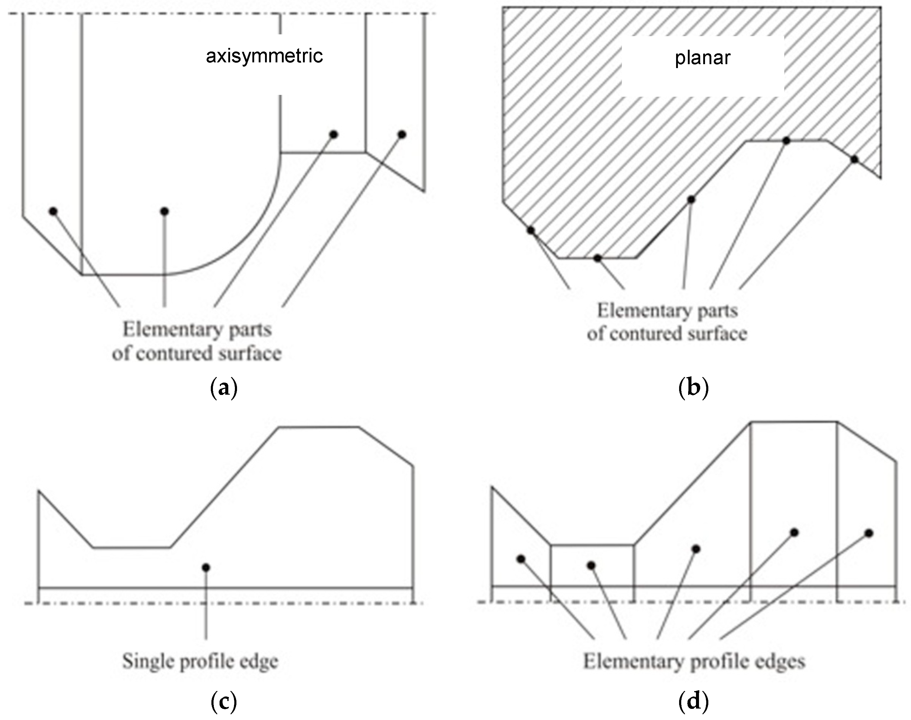
2.1. Universal Form Tool with a Multi-Insert Profile

The design of the universal form tool presented in this paper is based on the concept of variable tool configuration, which is achieved by changing the cutting-edge elements and their geometry [39,42,43]. Multi-edge tools are constructed with the ability to change their geometrical characteristics and this feature distinguishes them from conventional fixed geometry tools. This concept is referred to as geometric and kinematic flexibility (GKF) of the tool [42]. Sandvik’s solution is an example of implementation [40,41].
New tool designs that incorporate the GKF concept could potentially replace many current designs available on the market. The GKF tool concept is based on the assumption that the outline of an object consists of simple single profiles. When those profiles are combined in different configurations, new surface profiles can be generated. Examples of the surface division of axisymmetric and planar objects into single profiles are presented in Figure 1a,b, respectively.
In traditional forming tools, the entire profile is a single tool, limiting its use to a single profile (see Figure 1c). This principle applies to both axisymmetric and planar surfaces.
The cutting edges in the concept of the universal profile tool are assembled from severalsingle multi-inserts, to create the desired profile, as indicated in Figure 1d. The modular design concept of the cutting edge can be processed by the same set of single inserts for the machining of a wide class of surface contours. For example, assuming a single application of the single insert with a different profile number, N, of different machined surface profiles can be determined as the variances without repetition:
N = n ! ( n i ) !
where n is the number of multi-inserts, and i is the number of surfaces.
Table 1 shows the number of different machined surface made from single inserts based on Equation (1). Calculation results indicate the possibility of creating many different surface profiles using a limited number of edges as shown in Table 1.
In the case of form tools for turning, the cutting edges should have one rake surface and in the case of milling tools, shaped edges should be arranged on the circumference of the tool, to avoid tool vibration and shock during simultaneous operation of all cutting edges.

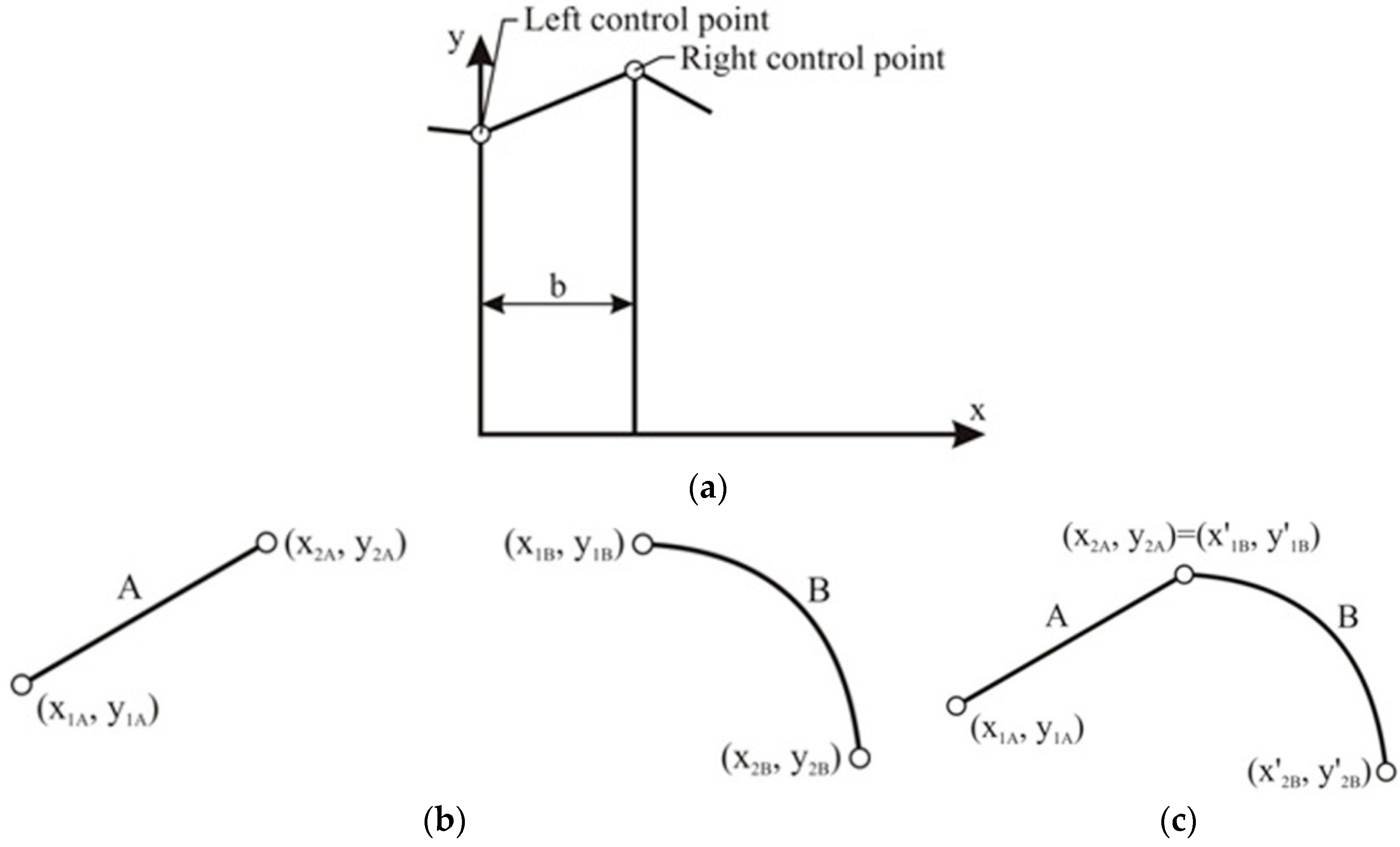
2.2. Principle of the Build Outline of the Multi-Insert Form Tool

Form tool outline synthesis requires a special procedure. Each individual cutting-edge shape is represented by two side control points as shown in Figure 2a. Control points are used to align different cutting elements, in order to create a continuous outline. Each profile is described in the Cartesian coordinate system. Coordinates on the y-axis represent the distance from the direction of the tool base to the workpiece. Direction x represents the workpiece axis (in case of an axisymmetric object). The base of the individual insert is described with coordinates: x1 = 0 and x2 = b, where b is the width of the single insert. Figure 2b,c present the idea of profile assembly from individual cutting edges.
Achieving continuous outline profiles requires an adjustment of the y coordinate of the tool to align it with the neighboring sections. The required offset can be calculated using the following equation:
y 1 B / = y 2 A .
Displacement d of point B of the edge can be calculated as follows:
d = y 2 A y 1 B .
These values are calculated and presented as the tool setting in the self-made software Tool_Shape. The value of the x coordinate remains unchanged.

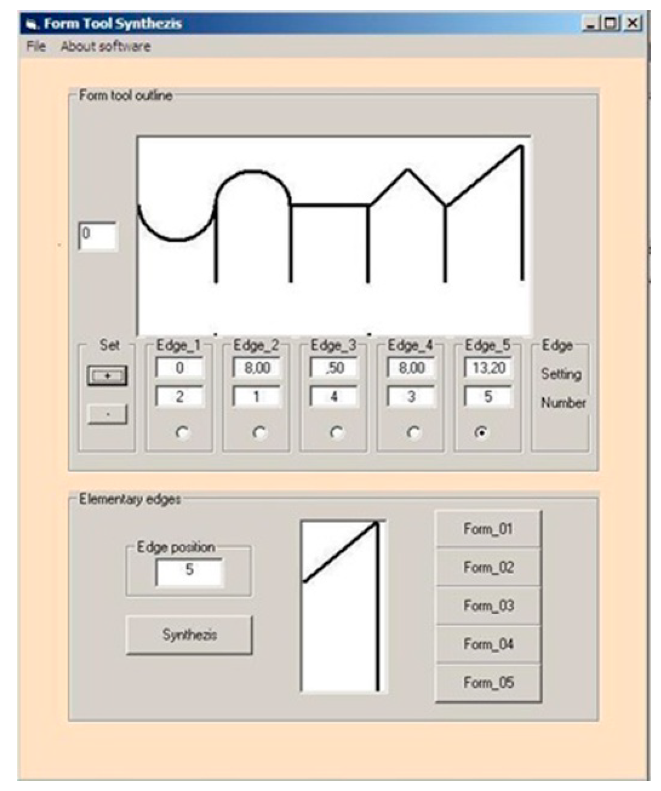
2.3. Computer-Aided Selection of the Outline of the Cutting Edge

A software program was developed using Visual Basic version 6.0. in order to select an outline of the folding cutting edge. The software tool is called Tool_Shape and it allows a virtual synthesis of the cutting edge of form tool using the number of inserts stored in a database (see Figure 3).
Multiple insert selection is shown in the main window of the software. The outlines of the edges are introduced into the software knowledge base in the lower part of the software window. Single edges may be contained in the form of graphic files, which can be either simple sketches or photos of the actual single edges. The offsets of the edges are calculated after pressing the synthesis button. The software automatically calculates the necessary tool position to generate a continuous outline according to the scheme presented in Figure 2c. It permits manual changes to the position of the edge using the axial movement of the edge d by using the + and − buttons. The resulting outline can be printed, together with information on the edge settings.
The customized software is suitable for the selection of the insert to match the desired outline and for presentation of the form tool specification and outline. Future additions to the Tool_Shape software are planned by enabling automatic single profile selection for the multi-edge tool based on the desired outline shape. Some further discussion is needed here on the mathematical expression/tools required to select the profile shape with either some specific curve types or arbitrary types.

3. Results and Discussion

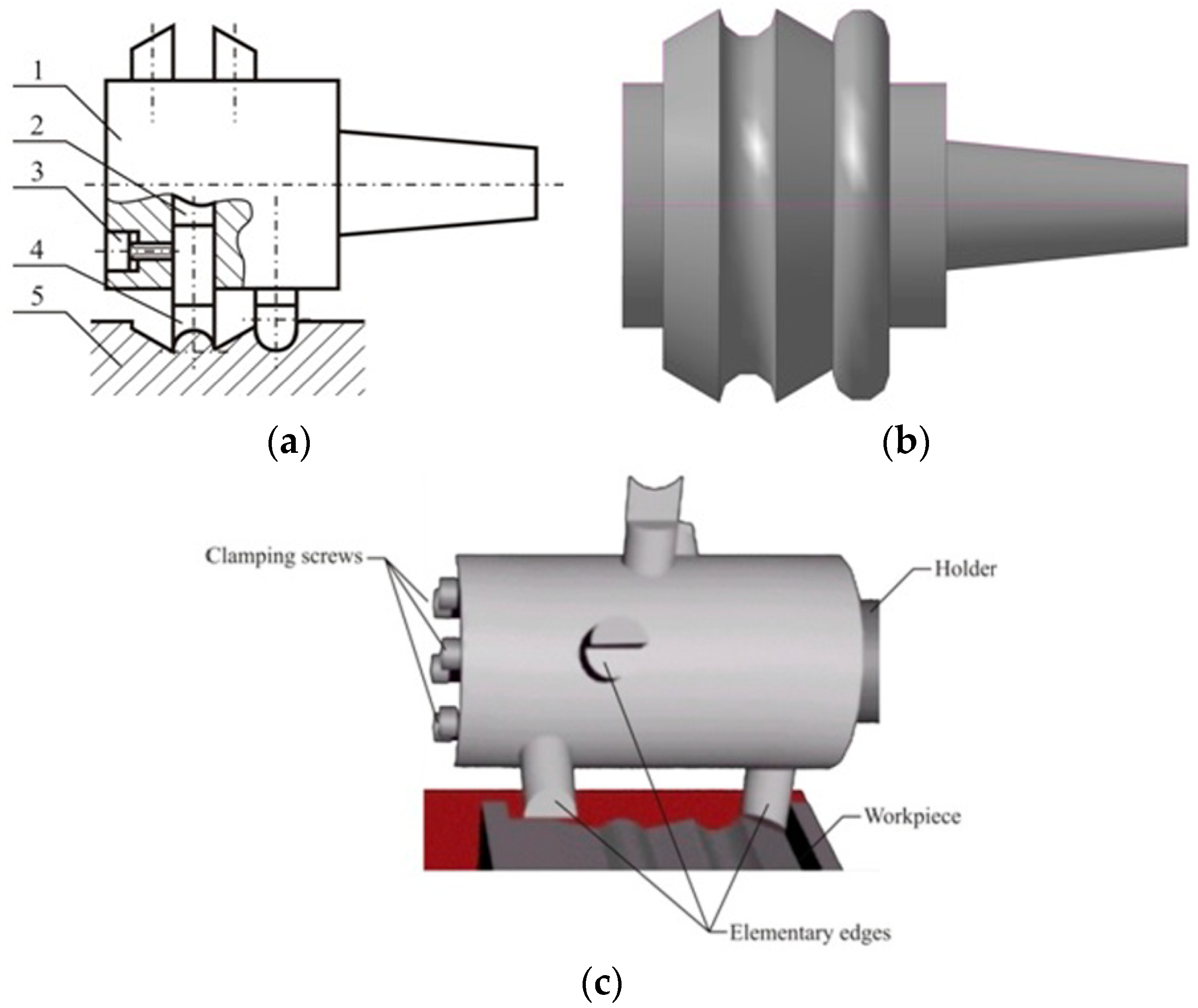
3.1. Universal Form Tool for Turning

The design concept of the form tool presented in Figure 1b was turned into a prototype of a new turning tool. Examples of single profile edges are presented in Figure 4a. All edges have the same rake angle, γo = 0°, and clearance angle, α0 = 10°. The values of kr are presented in Figure 4a. Figure 4b visualizes the surfaces machined with the example of the proposed tool. The multi-edge tool holder clamps the single inserts in place with fixing screws. The holder also has adjustment or setting screws along the radial direction for single cutting-edge position adjustment. Assembly of the tool is possible with a set of extra screws for increasing tool stiffness. Radial adjustment of the edge position is therefore possible, while the width depends on the dimensions of the single cutting edge, which in the prototype design is equal to the distance between the screws. The height of the holder was selected for installation on a universal lathe. This innovative solution is registered under a Polish patent [39].
The virtual model of the form tool as shown in Figure 4b is especially convenient for GKF tool analysis [39]. Changing the surface contour can be achieved by changing the position of the edges or replacing them with other edges. The number of achievable profiles is shown in the relationship (1) and is illustrated in Table 1.
The setting screws also allow for accurate positioning of the edge in the radial direction. The geometry of the flank, however, must always be checked. The cutting edges were prepared with a rake angle of γo = 0°, to facilitate the application of the edge and its insertion. These settings are in most cases sufficient for the machining of a variety of materials. The rake angle can be increased by setting the edge above the axis, but care must be taken to maintain the appropriate value of the clearance angle. The prototype tool was manufactured based on the CAD model using individual inserts that were machined from a 10 × 10 × 60 mm blocks of HSS SW18 steel.
First, a CAD model of an object with multiple profiles was generated, as shown in Figure 4c, to validate the design performance of the form tool. Turning tests were then conducted on PA4T material at a cutting speed of vc = 100 m/min and at a feed rate of f = 0.067 mm/rev. A sample outline of a machined surface (Ra = 1.02 m) is presented in Figure 4c. The tests validated that the design and the machined surfaces had the same contours. For the used feed rate, the cutting time was much shorter than for longitudinal turning (about 4 times).
A significant value of the rake angle was used for wood processing. When using a rake surface made of single edges, this angle can be obtained by positioning the edge above the turning axis. However, the resulting shape of the surface will therefore deviate from the shape of the contour of the cutting edge. Further examples of different shapes (at least in the CAD model) using the same tool must be shown for validation of the universal form tool in the turning operation. A new problem specific for the presented tools, in the field of turning where a common folded rake face is used, is the wear of the edges in the area of contact of neighboring edges of the folded profile. This should be the subject of further research.

3.2. Universal Form Tool for Milling

A universal shaped cutter prepared in accordance with the concept shown in Figure 1d is presented in Figure 5 and Figure 6a. The tool, shown in Figure 5a, consists of a holder (1), sockets (2), and inserts (3) that are positioned in the sockets, arranged around the holder, and offset from each other. A clamping screw (4) fixes each insert in place. The inserts (3) are made with different outlines of the multi-insert tool to form specific contoured features on the work piece (5). Use of a cylindrical holder in the tool enables tool rotation [42]. Each single edge shapes a fraction of the surface, machining only one type of detail. An example is shown in Figure 5b of a machined surface with a multi-insert configuration.
The main advantage of the multi-insert tool presented here is its capability to machine a large number of complex surface contours using only a limited number of single edges. A virtual model of the tool–work object interaction was prepared and is presented in Figure 5c.
Changes in the cutting tool outline were achieved by adjusting the insert position of the cutting tool in the holder and its location. These features of the GKF milling cutter distinguish it from the conventional shape cutter that can only be used for obtaining one particular surface shape. Sometimes multi-edge tools are used with a single cutter; however, currently available solutions are not as universal as the GKF tool presented in this paper. The multi-insert tool prototype is shown in Figure 6a, while the examples of single edges are presented in Figure 6b. The design of this novel tool is patented [43].
Single inserts were fitted into the sockets of the holder that permit radial distance adjustment for each edge individually. These single edges are made from cylindrical HSS. The rake angle and the clearance angles were set at γ0 = 0° and α0 = 10° ± 0.5, respectively. The value of the kr area is also listed in Figure 6b. The body of the multi-insert cutter (Figure 6a) has 12 transverse holes that are radially spaced out at 45° with respect to each other. The distance along the axis of the main body between apertures spaced at 90° intervals is equal to the diameter of the hole, and the openings are offset at angles of 45° with respect to the preceding hole. All holes have diameters of 0.5.
In the experiments, 12 wooden surfaces were machined using the universal form tool for milling to validate its performance, and the machined surfaces are shown in Figure 6c. A cutting speed of vc = 150 m/min and a feed rate of f = 100 mm/min was used in the machining process. Employing a small number of single edges, we can achieve many other profiles by repositioning the single insert. In this case, the edges form a coverage area of the cutter that forms the contoured surface. Precise alignment of the characteristic points of the single edges common to neighboring edges is required for accurate machining results.

4. Summary and Conclusions

The innovative design of a universal form tool for surface machining based on elementary shapes of the surface profiles is presented in this paper. The presented tools are innovative and are patented [39,43]. The shape of the multi-insert tool can be quickly adjusted by manipulating the order and the type of the single inserts. This idea can be applied to the machining of both axisymmetric and planar surfaces using turning and milling, respectively. The application of the tool in turning and milling operations is presented with examples of achievable profiles. The proposed solution of form tool design with multi-insert configurations is capable of machining a large number of different surface shapes with a limited number of single edges.
The following conclusions can be formulated:
  • An addition to an array of GKF tools, this tool permits the replacement of a few fixed geometric tools with a multi-insert- cutting edge tool. The feature may be particularly important for flexible production in small series. The use of this tool type can reduce the cost of tool manufacturing required in traditional form tool designs.
  • A special feature of the proposed tools is the ability to obtain many different profiles using a small number of single inserts with other profiles. A working prototype was tested under practical working conditions, in both turning and milling.
  • The given equation allows for prediction of the number of different profiles using several components of a multi-insert tool.
  • Virtual modeling of the tool was extensively used during the design process of the tool. These CAD models entail the opportunity for virtual analysis of the model prior to physical testing. This feature is especially important in the case of GKF tools, where it is possible to change the form of tools and adjust or replace single edges after visualizing the resulting surface profile without any need for physical tests.
  • The Tool_Shape software can generate an outline and provide the settings for single inserts for the proposed tool solutions for both turning and milling.
  • An example of machining using the presented innovative tool is presented with a multi-insert cutting edge. These tools can be used both for turning and milling. It is possible to use these tools in both the woodworking and machining of aluminum alloys.
  • In the cutting process using these tools, the range of the cutting speed effect on the wear of individual edges and the influence of cutting speed on the surface roughness could be found.
  • In turning, profile diameters along the turning axis are key in determining contact segments during machining. Offsets perpendicular to the axis of symmetry affect profile dimensions and can double the tool shape error. To increase the rake angle, it is advisable to cut above the axis.
  • In milling, shape errors still need to be investigated in future research. Definition of the contact points of machined material with compound multi-insert cutting edges is a problem. In case the tool’s stiffness is insufficient, vibrations may occur resulting in poor surface quality. A multi-insert tool is particularly suitable for use in the furniture industry and can produce complex shapes by moving single inserts.

Author Contributions

Conceptualization, T.M., D.Y.P., and H.L.; methodology, T.M., D.Y.P., and H.L.; software, T.M. and H.L.; validation, T.M. and T.P.; formal analysis, T.M., H.L., and A.K.; investigation, T.M., H.L. and A.K.; resources, T.M., H.L., and A.K.; data curation, M.K.G., T.M., H.L., and A.K.; Writing—Original Draft preparation, M.K.G., T.M., D.Y.P., K.P., and A.K.; Writing—Review and Editing, M.K.G., T.M., D.Y.P., C.I.P., K.P., G.K., and M.M.; visualization, T.M., D.Y.P., and M.M.; supervision, T.M., D.Y.P., K.P., G.K., and M.M.; project administration, T.M.; funding acquisition, D.Y.P. and C.I.P.

Funding

The study was supported under Act 211 Government of the Russian Federation, contract Nr. 02.A03.21.0011.

Conflicts of Interest

The authors declare no conflict of interest.

Nomenclature

nNumber of single edges
iNumber of surface profiles
NNumber of different machined surface profiles
bSingle edge width
x1, y1Coordinates of the left control point
x2, y2Coordinates of the right control point
dVertical distance between neighboring edges control points
y’Control point y coordinate after offset is applied
γnRake angle
αnClearance angle
rεNose radius
kr/Primary main cutting angle
kr//Secondary main cutting angle
vcCutting speed
fFeed rate
ftFeed rate

References

  1. Nayak, P.K.; Shunmugam, M.S. CAD simulation and generation machining of discrete ring-involute spherical segment gear pair. Proc. Inst. Mech. Eng. Part C J. Mech. Eng. Sci. 2012, 226, 1832–1844. [Google Scholar] [CrossRef]
  2. Denkena, B.; Biermann, D. Cutting edge geometries. CIRP Ann. Manuf. Technol. 2014, 63, 631–653. [Google Scholar] [CrossRef]
  3. Filippov, A.V.; Filippova, E.O.; Chazov, P.A. Cutting-force components in turning by tools with no cutting tip. Russ. Eng. Res. 2016, 36, 1040–1043. [Google Scholar] [CrossRef]
  4. Omirou, S.L.; Rossides, S.; Lontos, A. A new CNC turning canned cycle for revolved parts with free-form profile. Int. J. Adv. Manuf. Technol. 2012, 60, 201–209. [Google Scholar] [CrossRef]
  5. Peng, F.Y.; Ma, J.Y.; Wang, W.; Duan, X.Y.; Sun, P.P.; Yan, R. Total differential methods based universal post processing algorithm considering geometric error for multi-axis NC machine tool. Int. J. Mach. Tools Manuf. 2013, 70, 53–62. [Google Scholar] [CrossRef]
  6. Wu, B.; Liang, M.; Zhang, Y.; Luo, M.; Tang, K. Optimization of machining strip width using effective cutting shape of flat-end cutter for five-axis free-form surface machining. Int. J. Adv. Manuf. Technol. 2017, 94, 2623–2633. [Google Scholar] [CrossRef]
  7. Erol, N.A.; Altintas, Y. Open architecture modular tool kit for motion and machining process control. IEEE/ASME Trans. Mechatron. 2000, 5, 281–291. [Google Scholar] [CrossRef]
  8. Altintas, Y.; Erol, N.A. Open architecture modular tool kit for motion and machining process control. CIRP Ann. Manuf. Technol. 1998, 47, 295–300. [Google Scholar] [CrossRef]
  9. Boryczko, A. Measurement of relative tool displacement to the workpiece for the assessment of influences of machining errors on surface profiles. Meas. J. Int. Meas. Confed. 2002, 31, 93–105. [Google Scholar] [CrossRef]
  10. Tang, Q.; Zhang, Y.; Jiang, Z.; Yan, D. Design method for screw forming cutter based on tooth profile composed of discrete points. J. Mech. Des. Trans. ASME 2015, 137, 085002. [Google Scholar] [CrossRef]
  11. Urbikain, G.; López De Lacalle, L.N.; Campa, F.J.; Fernández, A.; Elías, A. Stability prediction in straight turning of a flexible workpiece by collocation method. Int. J. Mach. Tool. Manuf. 2012, 54–55, 73–81. [Google Scholar] [CrossRef]
  12. Balandin, A.D.; Mishkin, S.V. Calculation of cut-in profile cutters using KOMPAS 3D V8 graphic software. Russ. Eng. Res. 2007, 27, 220–225. [Google Scholar] [CrossRef]
  13. Filippov, A.V. Cut-layer cross section in oblique turning by a single-edge tool with a curved rear surface. Russ. Eng. Res. 2015, 35, 385–388. [Google Scholar] [CrossRef]
  14. Maruda, R.W.; Krolczyk, G.M.; Nieslony, P.; Wojciechowski, S.; Michalski, M.; Legutko, S. The influence of the cooling conditions on the cutting tool wear and the chip formation mechanism. J. Manuf. Process. 2016, 24, 107–115. [Google Scholar] [CrossRef]
  15. Nieslony, P.; Krolczyk, G.M.; Wojciechowski, S.; Chudy, R.; Zak, K.; Maruda, R.W. Surface quality and topographic inspection of variable compliance part after precise turning. Appl. Surf. Sci. 2018, 434, 91–101. [Google Scholar] [CrossRef]
  16. Raja, J.; Whitehouse, D.J. An investigation into the possibility of using surface profiles for machine tool surveillance. Int. J. Prod. Res. 1984, 22, 453–466. [Google Scholar] [CrossRef]
  17. Khan, M.R.; Tandon, P. Mathematical modeling of a generic multi-profile form milling cutter. Proc. Inst. Mech. Eng. Part C J. Mech. Eng. Sci. 2013, 227, 1036–1046. [Google Scholar] [CrossRef]
  18. Kuts, V.V.; Malneva, Y.A.; Skantsev, V.M. Development and testing of profile shafts processing method with constructive feed cutters. Procedia Eng. 2016, 150, 696–701. [Google Scholar] [CrossRef]
  19. Sun, Q.Y.; Wang, Z.W.; Shan, Y.X.; Bai, Y.F. Method for design of integral shaped milling cutter profile. Adv. Mater. Res. 2011, 328–330, 771–774. [Google Scholar] [CrossRef]
  20. Wojciechowski, S.; Maruda, R.W.; Krolczyk, G.M.; Niesłony, P. Application of signal to noise ratio and grey relational analysis to minimize forces and vibrations during precise ball end milling. Precis. Eng. 2018, 51, 582–596. [Google Scholar] [CrossRef]
  21. Krolczyk, G.M.; Nieslony, P.; Maruda, R.W.; Wojciechowski, S. Dry cutting effect in turning of a duplex stainless steel as a key factor in clean production. J. Clean. Prod. 2017, 142, 3343–3354. [Google Scholar] [CrossRef]
  22. Mikolajczyk, T.; Latos, H.; Paczkowski, T.; Pimenov, D.Y.; Szynka, T. Innovative tools for oblique cutting. Procedia Manuf. 2018, 22, 166–171. [Google Scholar] [CrossRef]
  23. Mikolajczyk, T.; Latos, H.; Paczkowski, T.; Pimenov, D.Y.; Szynka, T. Using CAD CAM system for manufacturing of innovative cutting tool. Procedia Manuf. 2018, 22, 160–165. [Google Scholar] [CrossRef]
  24. Kecik, K.; Ciecielag, K.; Zaleski, K. Damage detection of composite milling process by recurrence plots and quantifications analysis. Int. J. Adv. Manuf. Technol. 2017, 89, 133–144. [Google Scholar] [CrossRef]
  25. Seguy, S.; Campa, F.J.; de Lacalla, L.N.L.; Arnaud, L.; Dessein, G.; Aramendi, G. Toolpath dependent stability lobes for the milling of thin-walled parts. Int. J. Mach. Mach. Mater. 2008, 4, 377–392. [Google Scholar] [CrossRef]
  26. Mia, M.; Dhar, R.N. Prediction of surface roughness in hard turning under high pressure coolant using Artificial Neural Network. Measurement 2016, 92, 464–474. [Google Scholar] [CrossRef]
  27. Yuan, W.; Tang, Y.; Yang, X.; Liu, B.; Wan, Z. On the processing and morphological aspects of metal fibers based on low-speed multi-tooth dry cutting. Int. J. Adv. Manuf. Technol. 2013, 66, 1147–1157. [Google Scholar] [CrossRef]
  28. Chiang, C.J.; Fong, Z.H. Design of form milling cutters with multiple inserts for screw rotors. Mech. Mach. Theory 2010, 45, 1613–1627. [Google Scholar] [CrossRef]
  29. Nadolny, K.; Kapłonek, W. Analysis of flatness deviations for austenitic stainless steel workpieces after efficient surface machining. Meas. Sci. Rev. 2014, 14, 204–212. [Google Scholar] [CrossRef]
  30. Kapłonek, W.; Nadolny, K.; Krolczyk, G.M. The use of focus-variation microscopy for the assessment of active surfaces of a new generation of coated abrasive tools. Meas. Sci. Rev. 2016, 16, 42–53. [Google Scholar] [CrossRef]
  31. Mikolajczyk, T. Analyse of possibility of form tools manufacturing using wire cutting EDM. Appl. Mech. Mater. 2014, 656, 200–205. [Google Scholar] [CrossRef]
  32. Zhong, Z.W.; Hiziroglu, S.; Chan, C.T.M. Measurement of the surface roughness of wood based materials used in furniture manufacture. Measurement 2013, 46, 1482–1487. [Google Scholar] [CrossRef]
  33. Pereira, O.; Rodríguez, A.; Fernández-Abia, A.I.; Barreiro, J.; López de Lacalle, L.N. Cryogenic and minimum quantity lubrication for an eco-efficiency turning of AISI 304. J. Clean. Prod. 2016, 139, 440–449. [Google Scholar] [CrossRef]
  34. Polvorosa, R.; Suárez, A.; de Lacalle, L.N.L.; Cerrillo, I.; Wretland, A.; Veiga, F. Tool wear on nickel alloys with different coolant pressures: Comparison of Alloy 718 and Waspaloy. J. Manuf. Process. 2017, 26, 44–56. [Google Scholar] [CrossRef]
  35. Pereira, O.; Martín-Alfonso, J.E.; Rodríguez, A.; Calleja, A.; Fernández-Valdivielso, A.; López de Lacalle, L.N. Sustainability analysis of lubricant oils for minimum quantity lubrication based on their tribo-rheological performance. J. Clean. Prod. 2017, 164, 1419–1429. [Google Scholar] [CrossRef]
  36. Petrovic, A.; Lukic, L.; Ivanovic, S.; Pavlovic, A. Optimisation of tool path for wood machining on CNC machines. Proc. Inst. Mech. Eng. Part C J. Mech. Eng. Sci. 2017, 231, 72–87. [Google Scholar] [CrossRef]
  37. Fan, J.-W.; Li, Y.; Gao, X.-L.; Wang, X.-F. Design of formed milling cutter for screw of oil extraction progressing cavity pump based on non-instantaneous envelope method. Beijing Gongye Daxue Xuebao/J. Beijing Univ. Technol. 2013, 39, 19–24. [Google Scholar]
  38. Olgun, U.; Budak, E. Machining of difficult-to-cut-alloys using rotary turning tools. Procedia CIRP 2013, 8, 81–87. [Google Scholar] [CrossRef]
  39. Mikołajczyk, T. Form Tool. Patent PL No 216160, 31 March 2014. [Google Scholar]
  40. Sandvik Coromant. Available online: https://www.sandvik.coromant.com/pl-pl/products/coroplex_mt/pages/default.aspx (accessed on 28 February 2019).
  41. Sandvik Coromant. Available online: https://www.sandvik.coromant.com/en-gb/campaigns/primeturning/pages/default.aspx?internal_camplink=primeturning&internal_camplink_type=highlight (accessed on 28 February 2019).
  42. Latos, H. Geometric and Kinematic Flexibility of Cutting Tools; Publishing House of the Technical and Agricultural Academy: Bydgoszcz, Poland, 1997. [Google Scholar]
  43. Mikołajczyk, T. Form Cutter. Patent PL No 216166, 31 March 2014. [Google Scholar]
Figure 1. An example of (a) an axisymmetric contoured surface, (b) a planar contoured surface, (c) a single edge profile, (d) a profile combining from another multi-insert.
Applsci 09 00880 g001
Figure 2. Concept of setting form tool: (a) the coordinate system of the single insert, (b) the control point of the example profile of two inserts, and (c) the cutting edge settings on a continuous multi-insert line.
Applsci 09 00880 g002
Figure 3. Screenshot of the Tool_Shape software for insert selection and positioning.
Applsci 09 00880 g003
Figure 4. Multi-edge form tool with single cutting edges: (a) examples of single edges of the multi-insert form tool (geometry of cutting edge for each part from left to right (axial feed): kr = 90°, kr = 45°, kr = 45°, kr / = 45°, εr = 90°, kr // = 45°, rε = 5 mm, and rε = −5 mm), (b) view of the virtual model of the tool, and (c) a sample object turned with the proposed multi-insert tool (CAD model and real object).
Applsci 09 00880 g004
Figure 5. Universal profile cutter with single inserts: (a) a sketch of the cutter [43], (b) an example of multi-insert configuration, and (c) virtual model of profile cutter in contact with the machined surface.
Applsci 09 00880 g005
Figure 6. View of (a) the multi-insert cutter prototype and (b) the inserts (geometry of the cutting edge for each part from left to right (axial feed): kr = 90°, kr = 45°, kr = 45°, kr / = 45°, εr = 90°, kr // = 45°, rε = 5 mm, and rε = −5 mm); (c) examples of 12 shaped surfaces machined with the proposed universal multi-insert profile-cutter.
Applsci 09 00880 g006aApplsci 09 00880 g006b
Table 1. Number N of different profile of machined surface calculated using Equation (1).
Number of Inserts, n
Number of Surfaces, i 12345678
112345678
2-261220304256
3--62460120210336
4---241203608401680
5----12072025206720

