Review

Environmental Effects on HV Dielectric Materials and Related Sensing Technologies

1
Centre for Technology Innovation, IntAIB, Melbourne 3136, Australia
2
Department of Electronics and Communication Engineering, ASET, Amity University, Noida, Uttar Pradesh 201313, India
3
Institute for Tropical Technology, Vietnam Academy of Science and Technology, 18 Hoang Quoc Viet street, Cau Giay district, Hanoi, Vietnam
4
School of Engineering, RMIT University, GPO Box 2476, Melbourne, Victoria 3001, Australia
*
Author to whom correspondence should be addressed.
Appl. Sci. 2019, 9(5), 856; https://doi.org/10.3390/app9050856
Submission received: 16 January 2019 / Revised: 19 February 2019 / Accepted: 20 February 2019 / Published: 27 February 2019
(This article belongs to the Special Issue Application of Sensors to Environmental, Food and Clinical Analyses)

Abstract

:
The increase in recent power failures, with negative impacts on humans and the economy, has been largely attributed to environmental effects and the aging of the power network. These have been accelerated in the last years due to two main factors: an increased load on the power network and material degradation owing to the presence of environmental pollutants. These factors together with specific weather conditions create the incipient conditions for power network degradation. In this paper, a review of the influence of environmental factors on high-voltage (HV) materials and components is provided. Sensing and artificial intelligence (AI) technologies developed to prevent the failure of the material structure and HV components are also reported.

1. Introduction

The delivery of power from generating sites to load centers is accomplished widely by overhead power lines. To minimize line losses, power transmission over such long distances is transmitted at high voltages of orders of kV. Energized high-voltage (HV) line conductors need to be attached to a support structure and to be electrically isolated from the support structures. The system that performs the dual function of support and electrical insulation is called the insulator. The nonconductive material of insulators provides a dielectric barrier between two electrodes of different electrical potential.
High-voltage insulators are present in the transmission and distribution system, including power transmission lines (e.g., at the locations where the lines are suspended). The most common insulators are made of ceramic, glass and polymeric materials. These types of HV insulators and their typical descriptors are provided in Table 1, in which the time when the insulators were introduced into the power network is included. Glass insulators appeared in early 1865 in the USA in the telegraph network [1], which was used by Edison to run the first electric power into New York city in 1882 [2]. Early insulators used in the power network in 1880 were made also of wood [2]. Although wood performed well in dry conditions, it led to unwanted problems in wet environments due to the leakage current paths created by the water. The porcelain insulators produced in 1880 were less prone to burning to the ground when short-circuits occurred [2]. This advantage opened the path to the HV ceramic insulators industry. The development and use of polymeric insulators started during the 1960s [3], and by 1990, they had become mature products and relatively popular in power networks [3,4], with a larger adoption in current years due to their outstanding characteristics.
The diversity, size and distribution of airborne pollution particles have been described by Thompson [5]. Typical organic, inorganic and water pollution particles and their size ranges are given in Table 2. Considering nonmagnetic particles, the forces that drive particles to the surface of insulators are gravity, wind and electric forces [6].

2. Analyses and Discussions

The degradation of the dielectric materials of HV insulators followed by their failure is an ongoing problem in the power network (PN). The main cause of insulator aging, degradation and failure is electrical discharge triggered by environmental factors and power overload.
The major sources of environmental pollution include costal pollution, rain forest algae/moss, desert pollution, snow, lighting and industrial pollution. Among them, the most impactful factors are pollutants in coastal environments [7]. In these environments, temperature exposure, radiative exposure, relative humidity or moisture level, the counter-diffusion of hydroxide ions, the environmental load of salts and other adverse climate conditions play a key role in the degradation of insulating materials. The effect of various types of contamination deposition on insulator surface dry band arching [8] and flashover [9,10,11,12,13,14,15] indicated the effect of direct contamination on the performance of insulators. The effect of wind speed on the accumulation of pollution in HV insulators was also investigated [16,17]. The high wind speed and direction are especially relevant along the ocean/sea shore, where the saline accumulation rate, diffusion and penetration rate and distance from the sea are closely related factors. Pollutants mainly comprise marine-specific soluble salts (NaCl and Na2SO4) dissolved in water droplets and carried by nano/micro bubbles. They lead to the development of a continuous water film and the distribution of pollution layers on the insulator surfaces, which can cover the surface of the insulators partially or totally. When the contaminated insulator surfaces become wet, some of these particles are dissolved, causing the insulator surfaces to become conductive [18,19,20,21]. To that end, the effect of wind and distance from the seaside on the insulating surface contamination was investigated [22].
The effects of deposits of sandstorms and free carbon particles (soot) on the flashover activity of ceramic and polymeric insulators were also investigated [23]. The study indicated that the deposition rate of soot particles was highly increased when both porcelain and polymeric insulators were already polluted with sand particles, regardless of whether the sand particles were charged or not. The work also demonstrated that moisture was critical to pollutant layer build-up and increased the severity of pollution. The effect of the desert sandstorms on the reliability of the HV insulators was considered [24]. The work showed that long-time exposure of sand particles to electric fields results in charging the sand particles deposited on the surfaces of insulators, which in turn can support surface discharge. Sand particles, classified as non-soluble pollution sources, were indicated to decrease the reliability of power networks [25]. An investigation of the contamination of 1.4 mg/cm2 sand particles in desert areas on ceramic insulators with a standard creepage distance of 31 mm/kV from phase to phase was performed [26]. The results indicated that this creepage distance is insufficient to withstand desert pollution. High-speed winds carrying sand in deserts are a major source of contamination for the HV insulators. This is also due to the fact that sand storms can cause insulator material erosion [27]. The hydrophobic stability of silicone rubber, which makes it suitable for these erosive conditions, is attributed to low molecular weight silicone components. These components are able to migrate and subsequently cover the aged surface layers to restore hydrophobicity. Studies on the flashover voltage (kV) of silicone rubber/ethylene propylene diene monomer blends of outdoor insulators in a desert environment [28] indicated that, for long-term use, the electrical performance of hydrophobic composite insulators such as the silicone rubber blend (%) should be increased. Studies in desert conditions also showed that thermoplastic insulators and their dielectric response under the tested thermoelectric-cum-ultraviolet irradiation performed better than the silicone rubber insulators [29]. The data provide information regarding the stability and performance of these composite insulators and allow an informed decision on the choice of the most suitable materials.
The impact of birds’ activity is also of concern, especially in areas with a large bird population. For example, the implications of excrement from birds perching on transmission towers on the 220-kV network installed by Southern California Edison Company led to reported flashovers [30].
Lightning strikes affect the performance of HV insulators both directly and indirectly. The direct effects are related to the direct interaction with insulators, while indirect effects are caused by transient HV pulses induced in other power network components such as power lines. Studies in this direction were carried out; for example, for 10 kV polymer insulators under different conditions for impulse, weather and insulator angle with respect to a cross-arm [31]. The results showed that the weather and insulator angle (with respect to the cross-arm) have a dominant influence on the values of breakdown voltage and leakage current for both negative and positive impulses.
Industrial pollution commonly constitutes of gases and solid particles which are the products of combustion processes. When combustion products are transported by wind, suspended carbon particles (soot) may be adsorbed onto the HV insulator surface due to gravity and electrostatic forces [32,33]. The layer of the soot particles on HV insulators become conductive due to the ionized atmosphere around the insulator and can cause a distortion of the electric field distribution [34,35,36]. This distortion enhances the electric field strength to a level which is larger than the air breakdown, leading to partial discharge.
The typical pollutants that have a negative impact on HV insulator performance are summarised in Table 3.
The severity of pollution can be quantified in terms of the equivalent salt deposition density (ESDD) in mg/cm2. Table 4 presents the insulator leakage distance to avoid flashover according to the IEC 60815 standard [38].
The presence of environmental stresses such as heat, UV radiation, wind, rain, snow, salt, smoke, moss, algae, sand, dust, carbon particles, ash, avian excrements and gases results in material degradation, which then leads to a decrease in the mechanical and electrical properties of HV insulators. This ultimately facilitates the appearance of abnormal electrical stresses such as arching, corona, partial discharge, leakage current and flashovers. This process is presented in Figure 1.
For outdoor electrical insulation in the power system, there are three different types of voltage stress [39]:
  • Normal operation and temporary power-frequency over-voltages;
  • Switching surge voltages;
  • Lighting surge voltages.
During normal operation, the power-frequency voltage stress is low. Power-frequency overvoltage is caused by abnormal operation such as faults and resonances caused by weather conditions and structural aging and degradation associated with mechanical loads. The magnitude of overvoltage in high and extra-high systems is usually less than 2 V and lasts for less than 0.5 seconds. The switching surge voltages are produced by switching operations and their magnitude and duration are typically less than 3 V and hundreds of microseconds, respectively. A lightning surge voltage can be very high—larger than 1000 kV—however, it is very short in duration and is independent of the system operating voltage.
For instance, along the sea shore in relatively clean environments where the contamination level of HV insulator surfaces are below a threshold (e.g., an equivalent salt deposit density (ESDD) < 0.01 mg/cm2, the insulation level required is dictated mainly by the switching surge and lighting surge voltages. In places where insulation contamination is high—for example, ESDD > 0.01 mg/ cm2—the length of the insulator is dictated by the power frequency operating voltage under specific weather conditions. In early years, these appeared to be satisfactory; however, as time passed and insulator surfaces, especially the under-surfaces of sheds that were not exposed to the cleaning action of the rain and snow, became contaminated, flashovers occurred in certain weather conditions and the aging of insulators was accelerated, leading to catastrophic insulator failure.
A systematic study of leakage current on high-voltage polyamide insulators under different pollution conditions was reported [40]. The work showed that, in the case of clean/dry and clean/wet insulators, the leakage current increases linearly with the applied voltage. However, in the case of pollution with saline solution, there is a nonlinear relationship between the applied voltage and leakage current, evolving to the total flashover of the HV insulators, which occurs more rapidly than in the previous cases. The presence of saline solution also favors partial discharge, which precedes the flashover event, and causes traces of erosion and tracking on the surface of insulators. The flashover and aging of silicon insulators were also investigated under different pollution severity levels under dry band arcing [41]. The results show that the electric field stress occurs at the edges of the dry band and not at the electrode ends as in the case of uniform pollution layers. The study also suggested that the polymeric content in the silicone rubber surface decreases after flashover while the hydrophobic content increases.
Hierarchical segmentation analysis was used to assess the effect of the atmospheric conditions on the risk of failure of HV insulators [42]. The significant variables of the study were the leakage current, ambient temperature, relative humidity, atmospheric pressure, solar radiation, level of precipitation and wind direction and speed. A flowchart of the process for the case of a substation is presented in Figure 2. The work also used the Kruskal–Wallis test [42] to determine the significant changes in the magnitude of pollution due to climate periods. The key result of the study was that leakage current was more common for insulators during dry periods than humid ones.
To minimize the effect of environmental effects on high-voltage insulating materials [43,44], the surface of insulators was modified to ensure a long service life. Besides achieving a high stability and resistance to environmental pollutants, the insulators are required to have excellent electrical and mechanical characteristics to withstand the associated stresses present when they are installed in a power network. Improvements of ceramic insulators surfaces were proposed in [45]. Coated polymeric insulators capable of having a useful and longer life than uncoated insulators when exposed to contamination and moisture were proposed [46,47,48,49,50,51] by maintaining a low leakage level, preventing dry band arching and minimizing water absorption, hence minimizing the risk of partial discharges or flashover. Improved insulators for icing and polluted environments were also proposed.
Niemi proposed a one-part room-temperature-curable organopolysiloxane composition which is applied to the outer surface of an electrical insulator of glass or porcelain so that the electrical insulator may maintain its high insulating properties even in the presence of moisture, air pollution, ultraviolet radiation and other outdoor stresses [52]. A coating for achieving contamination-resistant insulators was also proposed [53]. Exposure to sunlight and some artificial light can have adverse effects on the useful life of polymer coatings. UV radiation can break down the chemical bonds in a polymer. Since photodegradation generally involves sunlight, thermal oxidation takes place in parallel with photooxidation. The use of antioxidants during processing is not sufficient to eliminate the formation of photoactive chromospheres. UV stabilizers have been applied widely, and the mechanism of stabilization of UV stabilizers belongs to one or more of the following: (a) absorption/screening of UV radiation, (b) deactivation (quenching) of chromophoric excited states, (c) free radical scavengers, and (d) peroxidedecomposers. Methods of applying lotus-effect materials as a superhydrophobic protective coating for external electrical insulation system applications were proposed to prevent the attachment of water droplets which contain dust or other contaminants and to enhance the coating’s UV stability [54].
Polymer insulators covered with a polydimethylsiloxane (PDMS) housing, which are replacing ceramic insulators, were investigated to assess their service life through an accelerated aging process [55]. In the study, working insulators with different ages were collected from service, and the changes in the mechanical and electrical properties and hydrophobicity of the PDMS cover against aging time were measured. The work indicated that the probable service life estimated from accelerated aging conditions under high-temperature and high-power UV radiation is substantially less than that obtained from natural aging. This conclusion is explained by complex environmental conditions where multiple factors not readily accountable for in laboratory experiments contribute in tandem to the accelerated aging.
Methods and systems to clean the surface of insulator materials have been proposed [56] and are still used today on a scheduled basis, especially in the vicinity of the sea/ocean where dirt and salt can build up on the insulator surfaces. The cleaning is required as, when exposed to the moisture from dew, frost, or light rain, the dampened contaminants can conduct current and lead to partial discharge, flashover or the electrical failure of the insulator. Most insulator designs depend on wind and rain to clean the insulator surfaces, but, when natural cleaning is insufficient, other methods are required to clean the insulators. The cleaning systems usually use robotic arms and high-pressure systems to dispense cleaning liquids to clean and apply a silicon coating to improve the surface hydrophobicity.
Self-healing HV insulators with similar weather resistance properties throughout the used material were also reported [57] which are also suitable for high-voltage electrical insulators by using a silicon rubber composition.
Systems that can attach to the top or the bottom of the HV insulators to prevent surface leakage currents, corona discharges and the corrosive and erosive effects thereby produced were also proposed [58] to extend the operation life of the insulators. The devices, which attach to the region of the junction of insulators and their end fittings, have a disk-shaped semiconductor element with rounded edges and rounded-edge surface conduction. The system prevents surface currents and corona discharges by shunting the current through the semi-conductive disk and its surface conduction layer. The round configuration of the device also avoids any high-field points which might otherwise produce corona discharge on the surface of the device.
In spite of the development of improved insulators for polluted environments in many parts of the world, insulator contamination has become an important impediment to the supply of electrical energy. The typical electrical discharges present on high-voltage insulators—partial discharge, dry band arching and corona discharge—can compromise the security of the power network. Corona discharge occurs on the surface of insulators or adjacent insulators when the intensity of the electric field exceeds the breakdown strength of the surrounding air. The products of corona discharge are electromagnetic (EM) radiation, heat, and chemical compounds such as ozone (O3), nitrogen dioxide (NO2), and nitric acid (HNO3) [59]. The combined contribution of chemical and electromagnetic stresses increases the degradation of the HV insulators.
Experimental and theoretical studies have assessed corona discharge in high-voltage systems [60,61,62]. Early investigations addressed the behavior of HV cables under low-level radiation and thermal aging conditions [63] and reported that failure of insulators can occur under prolonged electrical and thermal conditions. Life prediction tools were proposed to estimate the age profile of HV cables and insulators based on low-level radiation, flashover voltage, and surface resistance [15,63]. The majority of studies have been concerned with electrical activities only around one insulator to quantify the power losses and electric field around the insulator [64,65,66,67,68].
The field transfer from an electrical discharge along the surface of a faulty insulator to other insulators in a cross-arm structure was investigated [69]. The study showed that the intensity of the field around adjacent insulators on the cross-arm can be between 5% and 30% of the intensity in the immediate proximity of the corona discharge. The computational and experimental results indicated that the field level at different locations along the cross-arm depends on the physical size and intensity of the discharge. The electrical stress due to this field increases together with inclement environmental conditions and can contribute to the electrical aging of the insulators, ultimately leading to their breakdown.
The influence of water droplet pollution on the discharge activity of insulating materials is of relevance to the power industry. The presence of water on the surface of insulators has been shown to significantly increase partial discharge activity [70]. This can lead to the aging of insulating materials and ultimately can cause the failure of high-voltage insulators. The presence of current channels, caused by carbonization, saline crystals, or water, can support the discharge events between water droplets, which are linked to these current paths. Extensive studies have been carried out to recognize the parameters that facilitate this type of discharge activity for droplets situated on horizontal surfaces [71,72,73]. The works carried out employed diverse surface techniques in tandem with HV methods [74]. These offered a comprehensive understanding of the relationship between the surface properties, droplet contents and voltage parameters that lead to electrical discharges.
The stages that precede flashover events are diverse, but the main ones are contamination build-up, wetting of the surface, leakage current and Ohmic heating, spot discharges, and the deterioration of insulating materials. These stages can develop over an extended period of time or can occur rapidly. They are dictated by weather conditions and the level of pollution in the environment.
One of the works that investigated the dynamics of water droplets in an electric field dates back to 1917 [75]. Zeleny used alcohol drops at the end of a tube to examine how they evolve into a conical shape from which a thread emerges before it disintegrates into small droplets under the electrical stress. Zeleny showed experimentally that the disintegration of water droplets is due to the instability rather than the formation of ionic currents. His criterion for instability was V2/r0T = C, where V is the potential, r0 is the radius of the droplet, T is the surface tension and C is a constant. Pioneering theoretical studies into the disintegration of water droplets under electric fields also showed that water droplets elongate in an electric field [76]. The study found that the droplets become unstable when their length was 1.9 times their equatorial diameter. Using a point-to-plane configuration, corona discharge has been examined by studying the disruption of water drops in electric fields and the secondary electron emission associated with this [77]. As corona discharge commonly takes place between the sheds of HV insulators, the work explored the vertical nature of this event. Furthermore, the influence of hanging water droplets on the corona activity and flashover events was assessed for ceramic insulators. The studies show that water droplets hanging on the metallic electrodes reduce the flashover voltage significantly [78]. Droplets hanging on the upper electrode have the largest effect. The presence of water only on the lower electrode also contributes significantly to the breakdown voltage. A similar behavior was observed in the case of ceramic insulators. The water droplets can reduce the breakdown voltage significantly and cause partial discharge on 22 kV rated ceramic insulators. This can cause the aging of HV infrastructure, which ultimately leads to their failure.
Partial discharge (PD) in HV technology [79,80] can cause the failure of HV components such as capacitors, cables, and inlet bushings. PD, which takes place within or on the surface of HV insulators, is a persistent problem in the power industry. Internal PD is initiated in faults such as cavities within insulating materials, while external PD occurs on the surface of insulators or at the metal–insulator interface. Both kinds of PD can be described by a similar electrical discharge process. This discharge is known as Townsend electron avalanches, which can develop into streamers and micro-sparks [81,82]. Diverse electromagnetic (EM) techniques were proposed for the detection and monitoring of partial discharge activity in high-voltage infrastructure [83,84]. These methods employ EM sensors to detect the radiation emitted from PD activity and have been shown to provide valuable information on the condition of insulators. The propagation of EM radiation in isotropic media has been well explored [85]. Recent works use the finite difference time domain (FDTD) to simulate the propagation of the EM radiation emitted from PD on a distribution power line [86]. The radiation spectra along the line and in the proximity of a PD source was investigated for detection purposes. The radiation spectra of PD in dielectrics showed that the EM radiation propagates in HV insulating materials as dipoles or multipoles [87]. Different radiation patterns within distinct dielectric materials correspond to a different power density. The improvement of PD detection techniques relies on an accurate interpretation of the EM spectra emitted from discharge zones. A study of the coupling between the EM radiation generated by PD and electric or electronic systems is of real interest as novel sensing techniques use the available HV infrastructure to detect electrical faults [88]. The EM radiation emitted from PD can be characterized by its amplitude, frequency band and time of occurrence. These are determined by the rate of the ionization process and the dimensions of the cavities in which a plasma discharge (also called PD) is created [89]. The repetitive breakdown of gas within the dielectric cavities in insulators is the main source of intense EM radiation. The PD signal is characterized by the amplitude and spectral distribution of the EM signal. These characteristics, together with the rate of discharge activity, can assist in identifying the type of PD-related faults in the HV network.
It was shown in [90] that the radiation pattern emitted from a PD source from a fault-like cavity in a HV insulator is determined by the intensity of the source and the condition and geometry of the dielectric material. The diffraction pattern depends on the geometry and characteristics of insulating materials. The cross-sectional amplitude in tandem with field investigations showed that the power generated from a PD source depends on the media in which it is located. The results show that a PD fault sensor must discriminate between EM radiation emitted from different insulators to assess their remaining service life. This is required as power densities obtained from insulating materials with different dielectric constants can indicate different levels of aging. Systems and methods for detecting defects on insulators have been proposed [91], and methods for the characterization, monitoring and management of their condition [92,93,94,95,96,97,98,99,100,101,102,103,104,105,106,107,108,109,110,111] were assessed. To quantify the state of degradation of HV insulators, health indices for asset condition assessment were proposed [112].
Recently, electromagnetic sensors were employed to detect the electromagnetic radiation associated with defective insulators [84,113]. The electromagnetic sensing technique opened the path to the pre-fault detection of HV insulators using the overhead power line as the sensor [88,114]. In [115], the authors developed the proposed technology in an Internet of Things (IoT) technology that currently monitors 24/7 power networks for incipient faults that can lead to insulator failure and power network breakdown. The system is mainly intended for the early detection of faults in a low-voltage distribution network in which at least two detectors are each located on one of two power poles at either end of a section of a power distribution line. Each detector includes a GPS unit, an uninterruptable power supply, a means of communication to send data to a base station, antenna sensors with a bandwidth of 1 MHz to 3 GHz for each wire in the power line, and a processor to receive signals from each sensor and collect data relating to them to build estimation and prediction pertaining to the state of the power network.
A maintenance prioritization method, system and computer program product for HV insulators was also recently proposed [116]. The technology includes the collection of data including image data and status data for a plurality of HV components, such as power lines and bushings, building a three-dimensional image of each object, and estimating a risk factor of failure for each object by analyzing the information and the three-dimensional image of the object to compare with known characteristics of the object and a reference object description. A generic flow chart of the process is presented in Figure 3.
The process method and system proposed in [115] and [116] are intended to work in tandem to provide a comprehensive assessment of the power network.

3. Conclusions

This review covered some key environmental effects on the dynamics and life-time of ceramic and polymeric insulators. The study shows that high pollution levels are non-uniformly distributed and are correlated with, for example, industrial and marine regions. In these regions, the pollution, aging and degradation of insulator materials is accelerated compared to relatively unpolluted regions, where the degradation is more predictable over time. The rate of the environmental pollution of HV insulators depends on the weather conditions, surface roughness wettability, and insulator geometry. The mechanism of pollution of HV insulators is mainly governed by the gravity, wind forces, electrostatic forces, humidity, particle size and mass, and chemical properties of the insulators. The analyses indicate that the presence of pollutants on insulator surfaces leads to different types of electrical discharge such as corona, partial discharge and dry band arching which result in the accelerated degradation of insulators and the surrounding infrastructure and ultimately can cause flashover and blackouts. Although multiple methods were devised to improve the material surface of insulators, the surface pollution associated with aerial deposits and electromagnetic radiation cannot be totally avoided. To that end, methods to analyze, characterize, monitor and predict the state of the systems were devised. The most common technologies to carry out these tasks rely on sensors that operate in microwave, ultraviolet and visible spectra. The sensors are integrated in sensor networks or IoT systems to provide a more comprehensive picture of larger power networks. The sensing data streaming from these sensors are filtered and analyzed using statistical methods and artificial intelligence (AI) algorithms to make predictions of the health state of insulators under specific environmental and power-network-related stresses. The review also highlights the importance of taking multiple factors and technologies into account when designing the power grids of the future to alleviate some of these adverse effects.

Author Contributions

All the four authors have contributed equally to conceptualization, writing, review and editing.

Funding

This research received no external funding.

Conflicts of Interest

There is no conflict of interests.

References

  1. Jones, R. An Incomplete History and Timeline of Electric Telegraph and CD 731 Compromise Insulator, Hamilton, Ohio. 2010. Available online: https://www.insulators.info/shows/handouts/cd_731.pdf (accessed on 9 January 2019).
  2. Tod, J.H. A history of Electrical Porcelain Industry in the United States; Printed privately by Jack H. Todd. 1977. Available online: https://www.r-infinity.com/ebay/Electrical_Porcelain/Electrical_Porcelain_Adobe.pdf (accessed on 29 January 2019).
  3. Gençoglu, M.T. The comparison of ceramic and non-ceramic insulators. Nat and Appl. Sci. Electr. Eng. 2007, 2, 274–294. [Google Scholar]
  4. Hall, J.F. History and biography of polymeric insulators for outdoor applications. IEEE Trans. Power Deliv. 1993, 8, 376–385. [Google Scholar] [CrossRef]
  5. Thompson, W.C. The mechanism of the contamination of porcelain insulators. J. IEE 1944, 91, 317–327. [Google Scholar]
  6. Lambeth, P.J. Effect of pollution on high-voltage outdoor insulators. Proc. IEE Rev. 1971, 118, 1107–1130. [Google Scholar] [CrossRef]
  7. Sundararajan, R.; Mohammed, A.; Chaipanit, N.; Karcher, T.; Liu, Z. In-service aging and degradation of 345 kV EPDM transmission line insulators in a coastal environment. IEEE Trans. Dielectr. Electr. Insul. 2004, 11, 348–361. [Google Scholar] [CrossRef]
  8. Hussain, M.; Farokhi, S.; McMeekin, S.G.; Farzaneh, M. Dry Band Formation on HV Insulators polluted with Different Salt Mixtures. In Proceedings of the Annual Conference on Electrical Insulation and Dielectric Phenomena, Ann Arbor, MI, USA, 18–21 October 2015; pp. 201–204. [Google Scholar]
  9. El-Amine, M.S.; Hadi, H.; Flazi, S. Investigation on Influence of Salts Mixture on the Determination of Flashover Discharge Constant Part I: A Preliminary Study. In Proceedings of the IEEE Conference on Electrical Insulation and Dielectric Phenomena, Quebec, QC, Canada, 26–29 October 2008; pp. 674–677. [Google Scholar]
  10. Sima, W.; Yuan, T.; Yang, Q.; Xu, K.; Sun, C. Effect of nonuniform pollution on the withstand characteristics of extra high voltage suspension ceramic insulator string. IET Gen. Trans. Distrib. 2009, 4, 445–455. [Google Scholar] [CrossRef]
  11. Kimoto, I.; Fujimura, T.; Naito, K. Performance of insulators for direct current transmission line under polluted condition. IEEE Power Eng. Soc. 1972, PAS-92, 944–949. [Google Scholar]
  12. Naito, K.; Morita, K.; Hasegawa, Y.; Imakoma, T. Improvement of the dc voltage insulation efficiency of suspension insulators under contaminated conditions. IEEE Trans. Dielectr. Electr. Insul. 1988, 17, 1025–1032. [Google Scholar] [CrossRef]
  13. Seta, T.; Arai, N.; Udo, T. Natural pollution test of insulators energized with HVDC. IEEE Trans. Power App. Syst. 1974, 93, 878–883. [Google Scholar] [CrossRef]
  14. Kimoto, I.; Fujimura, T.; Naito, K. Performance of Insulators for direct current transmission line under polluted condition. IEEE Trans. Power App. Syst. 1973, 92, 943–949. [Google Scholar] [CrossRef]
  15. Venkataraman, S.; Gorur, R.S. Prediction of flashover voltage of non-ceramic insulators under contaminated conditions. IEEE Trans. Dielectr. Electr. Insul. 2006, 13, 862–869. [Google Scholar] [CrossRef]
  16. Venkataraman, R.; Gorur, S.; Mishra, A.P. Impact of weathering on flashover performance of nonceramic insulators. IEEE Trans. Dielectr. Electr. Insul. 2008, 15, 1073–1080. [Google Scholar] [CrossRef]
  17. Huafeng, S.; Zhidong, D.J.; Zhicheng, C.G.; Licheng, L. Mechanism of contaminant accumulation and flashover of insulator in heavily polluted coastal area. IEEE Trans. Dielectr. Electr. Insul. 2010, 17, 1635–1641. [Google Scholar]
  18. Horenstein, M.N.; Melcher, J.R. Particle contamination of high voltage DC insulators below corona threshold. IEEE Trans. Dielectr. Electr. Insul. 1979, 14, 297–305. [Google Scholar] [CrossRef]
  19. Lampe, W.; Hogluend, T.; Nellis, C.; Renner, P.; Stearns, R. Long-term tests of insulators under natural pollution condition at the big eddy test center. IEEE Trans. Power Del. 1989, 4, 248–258. [Google Scholar] [CrossRef]
  20. Fuzeng, Z.; Zhao, J.; Wang, M.L.; Zhicheng, C.G. Experimental investigation on outdoor insulation for DC transmission line at high altitudes. IEEE Trans. Power Deliv. 2010, 25, 351–357. [Google Scholar] [CrossRef]
  21. IEEE Standard Techniques for High Voltage Testing; (Std. 4–1987); IEEE: New York, NY, USA, 1995.
  22. Hussain, M.M.; Farokhi, S.; McMeekin, S.; Farzaneh, M. Mechanism of saline deposition and surface flashover on outdoor insulators near coastal areas part II: Impact of various environment stresses. IEEE Trans. Dielectr. Electr. Insul. 2017, 24, 1068–1076. [Google Scholar] [CrossRef]
  23. Dahham, I.A. Effect of the combined pollution of brick industry and sandstorms on the performance of high voltage insulators. Tikrit J. Eng. Sci. 2018, 1, 68–72. [Google Scholar]
  24. Abdel-Salam, H.H.; Nagat, M.K.A.; Bahaa, A.A. Effect of desert environmental conditions on the flashover voltage of insulators. Energy Convers. Manag. 2002, 43, 2437–2442. [Google Scholar]
  25. Ward, S.W.; Sanwar, M.R. A study of pollution effect on flashover phenomenon for south-west Iraqi (132kV) grid insulators. Al-Qadisiyia J. Eng. Sci. 2010, 3, 1–18. [Google Scholar]
  26. Challagondla, N.K. Behaviour of Water Drop on the Insulator Surface and Study of Electric Field Distribution on Parallel Insulators Under DC. Ph.D. Thesis, Brandenburg University of Technology, Brandenburg, Germany, 2015. [Google Scholar]
  27. Kataria, N.; Tiwari, K. Effect of environment pollution on the performance of power transmission lines: Insulator’s flashover. Int. J. Eng. Res. 2018, 7, 531–533. [Google Scholar]
  28. Nasrat, L.S.; Ibrahim, A.A.; Mortadda, H.A. Effect of environment desert conditions on the performance of hydrophobic polymer insulator surfaces. Int. J. Emerg. Technol. Adv. Eng. 2014, 4, 567–574. [Google Scholar]
  29. Jermi, A.; He, Y.; Khan, Q.U. Performance of high-voltage polymeric insulators under simulated environmental conditions in desert areas of Southern Libya. Trans. Electr. Electron. Mater. 2018, 19, 53–57. [Google Scholar] [CrossRef]
  30. Benson, E. Generating Infrastructural invisibility: Insulation, interconnection, and avian excrement in the Southern California power grid. Environ. Humanit. 2015, 6, 103–130. [Google Scholar] [CrossRef]
  31. Izadi, M.; Rahman, M.S.A.; Ab-Kadir, M.Z.A.; Gomes, C.; Jasni, J.; Hajikhani, M. The influence of lightning induced voltage on the distribution power line polymer insulators. PLoS ONE 2017, 12, e0172118. [Google Scholar] [CrossRef] [PubMed]
  32. Qi, B.; Li, C.R.; Hao, Z.; Geng, B.B.; Xu, D.G.; Liu, S.Y.; Deng, C. Surface discharge initiated by immobilized metallic particles attached to gas insulated substation insulators: Process and features. IEEE Trans. Dielectr. Electr. Insul. 2011, 18, 792–800. [Google Scholar] [CrossRef]
  33. Jiang, X.L.; Liu, Y.; Meng, Z.G.; Long, C.H.; Jin, X.; Zhang, Z.J. Effect of fog-haze on AC flashover performance of insulator. High Volt. Eng. 2014, 40, 3311–3317. [Google Scholar]
  34. Deng, H.M.; He, Z.H.; Xu, Y.H.; Ma, J.; Li, J. Effects of haze environment on discharge path under lightning impulses. High Volt. Eng. 2009, 35, 2669–2673. [Google Scholar]
  35. Wang, L.M.; Liu, D.; Chen, F.L.; Mei, H.W.; Lu, M. Simulation method and testing apparatus of fog-haze. High Volt. Eng. 2014, 40, 3297–3304. [Google Scholar]
  36. Liu, Y.Y.; Li, Y.; Wang, J.; Liang, X.D. Adhesion force and long-range attractive force between contamination particles and insulator surface. High Volt. Eng. 2014, 40, 1010–1016. [Google Scholar]
  37. Ramos, H.; Jose, A.; Compayo, M.; Jose, J. Insulator pollution in transmission lines. RE&PQJ 2006, 1, 124–130. [Google Scholar]
  38. International Electrotechnical Commission. Selection and Dimensioning of High-Voltage Insulators Intended for Use in Polluted Conditions—Part 1: Definitions, Information and General Principles; IEC TS 60815-1:2008; 2008; pp. 1–53. [Google Scholar]
  39. Nogol, O. High Voltage Insulators Constructed to Have Plural Dry Bands in Use. U.S. Patent 4,891,473, 1990. [Google Scholar]
  40. Slama, M.E.A.; Beroual, A. Behaviour of AC high voltage polyamide insulators: Evolution of leakage current in different surface conditions. Power Eng. Electr. Eng. 2015, 13, 74–80. [Google Scholar]
  41. Arshad; Nekahi, A.; McMeekin, S.G.; Farzaneh, M. Effect of pollution severity and dry band location on the flashover characteristics of silicone rubber surfaces. Electr. Eng. 2017, 99, 1053–1063. [Google Scholar] [CrossRef]
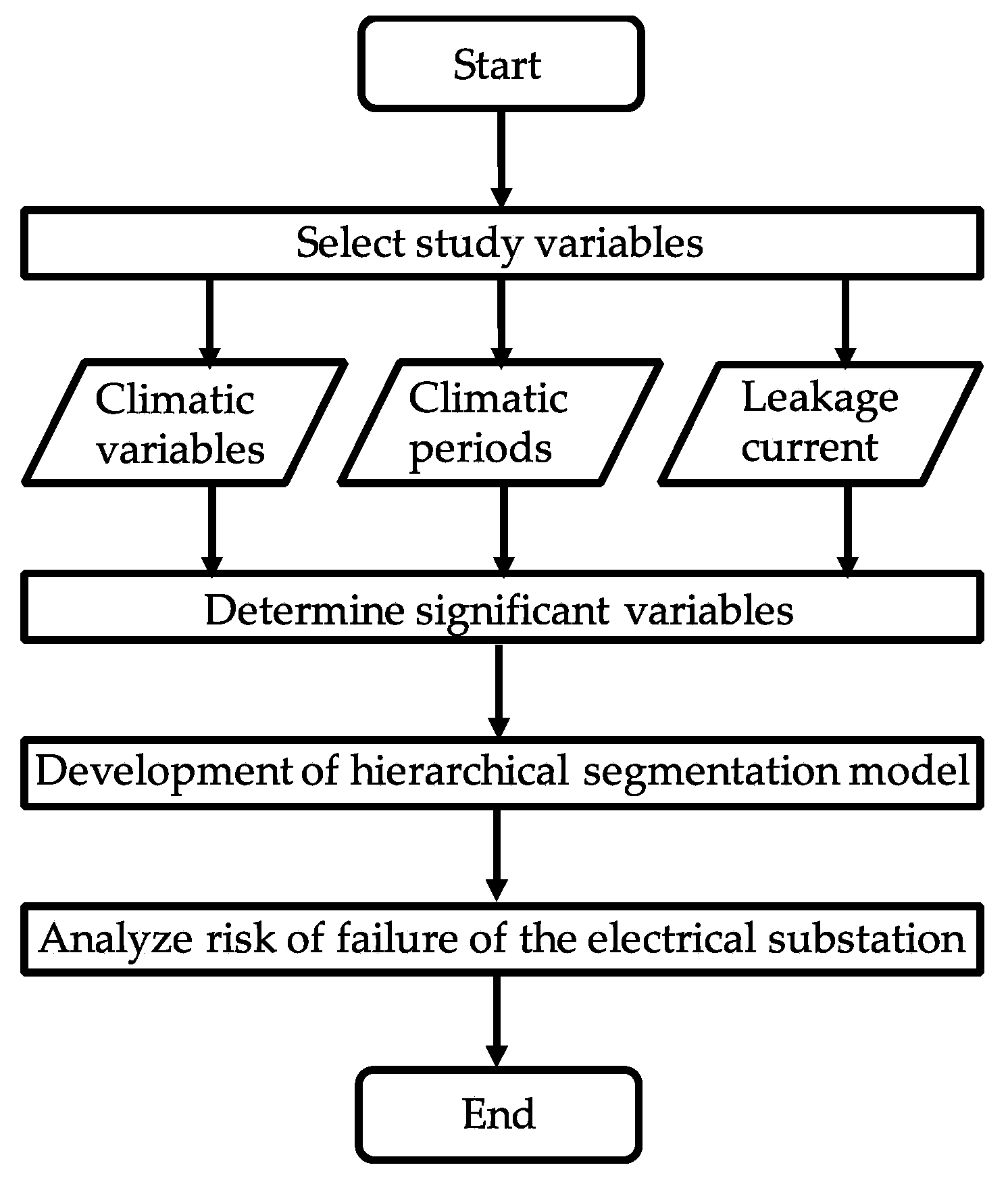
  42. Sierra, R.C.; Oviedo-Trespalacios, O.; Candelo, J.E.; Soto, J.D. Assessment of the risk of failure of high voltage substations due to environmental conditions and pollution on insulators. Environ. Sci. Pollut. Res. 2015, 22, 1–10. [Google Scholar]
  43. Imhof, A. High Voltage Insulator. U.S. Patent 2945912A, 1960. [Google Scholar]
  44. Denholm, A.S. High-Voltage Electrical Insulating Bushing. U.S. Patent 3126439A, 1964. [Google Scholar]
  45. Talcott, D.T. Weatherable Electrical Insulators made of Thermosetting Resin. U.S. Patent US 3,511,698, 1970. [Google Scholar]
  46. Mitsumatsu, Y.; Seike, S. High Voltage Porcelain Insulators. Patent EP0119838B1, 1987. [Google Scholar]
  47. Niemi, R.G. Method of Improving A High Voltage Insulator and Suitable Composition. Patent EP0123487B1, 1970. [Google Scholar]
  48. Amarasekera, J.; Doin, J.E. Silicone Compositions for High Voltage Insulator Applications. Patent EP0 928008A2, 1999. [Google Scholar]
  49. Phillips, A.J.; Birrell, D.S.; Childs, D.J. Aging Resistant, High Voltage Non-Ceramic Insulation. Patent 5,792,996, 1998. [Google Scholar]
  50. Greyling, C.J. Polymeric High Voltage Insulator with a Hard, Hydrophobic Surface. U.S. Patent 2010/0326699 A1, 2010. [Google Scholar]
  51. Chisholm, W.; Farzaneh, M. Environmental Exposure of Insulators for Icing and Polluted Environments; Wiley–IEEE Press: Hoboken, NJ, USA, 2009; pp. 59–154. [Google Scholar]
  52. Niemi, R.G. High Voltage Insulators. U.S. Patent 4476155A, 1984. [Google Scholar]
  53. Becker, K. Conductive Contamination Resistant Insulator. U.S. Patent US 2010/0108915 A1, 2012. [Google Scholar]
  54. Li, J.; Fan, L.; Wong, C.-P.; Lambert, F.C. Insulator Coating and Method for Forming Same. U.S. Patent 7,722,951 B2, 2010. [Google Scholar]
  55. Ghosh, D.; Khastgir, D. Degradation and stability of polymeric high-voltage insulators and prediction of their service life through environmental and accelerated aging processes. ACS Omega 2018, 3, 11317–11330. [Google Scholar] [CrossRef]
  56. Narain, G.H. Aparatus for Washing Electrical Insulators. U.S. Patent 5,041,164A, 1991. [Google Scholar]
  57. Meguriya, N.; Azechi, S.; Sekiguchi, S.; Yoshida, T. Silicone Rubber Compositions for High-Voltage Electrical Insulators and Polymeric Bushings. U.S. Patent 6,106,954A, 2000. [Google Scholar]
  58. Richards, C.N. Semiconductive Attachment Disc for Insulators to Reduce Electrical Stress Induced Corrosion. U.S. Patent 6,265,669 B1, 2001. [Google Scholar]
  59. Amin, M.; Akbar, M.; Khan, M.N. Aging Investigations of Polymeric Insulators: Overview and Bibliography. IEEE Electr. Insul. 2007, 23, 44–50. [Google Scholar] [CrossRef]
  60. Peek, F.W., Jr. Dielectric Phenomena in High Voltage Engineering, 3rd ed.; McGraw-Hill: New York, NY, USA, 1929. [Google Scholar]
  61. Korzhov, A.V.; Okrainskaya, I.S.; Sidorov, A.I.; Kufel’d, V.D. A study of electromagnetic radiation of corona discharge near 500-Kv electric installations. Power Tech. Eng. 2004, 38, 57. [Google Scholar] [CrossRef]
  62. Que, W.G.; Sebo, S.A.; Hill, R.J. Practical cases of electric field distribution along dry and clean nonceramic insulators of high voltage power lines. IEEE Trans. Power Deliv. 2007, 22, 1070–1078. [Google Scholar] [CrossRef]
  63. Gillen, K.T.; Clough, R.L. Anomalous aging phenomena in a crosslinked polyolefin cable insulation. Radiat. Phys. Chem. 1993, 41, 803. [Google Scholar] [CrossRef]
  64. Misaki, T.; Tsuboi, H.; Itaka, K.; Hara, T. Computation of three-dimensional electric field problems and its application to optimum insulator design. IEEE Trans. Power Appar. Syst. 1982, 101, 627. [Google Scholar] [CrossRef]
  65. Kaana-Nkusi, S.; Alexander, P.H.; Hackam, R. Potential and electric field distribution at a HV insulator shed. IEEE Trans. Electr. Insul. 1998, 23, 307–317. [Google Scholar] [CrossRef]
  66. El-Kishky, H.; Gorur, R.S. Electric potential and field along ac HV insulators. IEEE Trans. Dielectr. Electr. Insul. 1994, 1, 982–990. [Google Scholar] [CrossRef]
  67. Xu, G.; McGrath, P.B. Electrical and thermal analysis of polymer insulator under contaminated surface conditions. IEEE Trans. Dielectr. Electr. Insul. 1996, 3, 289–298. [Google Scholar]
  68. Kontargyri, V.T.; Gonos, I.F.; Stathopulos, I.A. Measurement and simulation of the electric field of high voltage suspension insulators. Eur. Trans. Electr. Power 2009, 19, 509. [Google Scholar] [CrossRef]
  69. Bojovschi, A.; Wong, K.L.; Rowe, W.S.T. Impact of electromagnetic radiation on cascaded failure in high voltage insulators. Appl. Phys. Lett. 2011, 98, 051504. [Google Scholar] [CrossRef]
  70. Rowland, S.M.; Lin, F.C. Stability of alternating current discharges between water drops on insulation surfaces. J. Phys. D Appl. Phys. 2006, 39, 3067–3076. [Google Scholar] [CrossRef]
  71. Zhu, Y.; Haji, K.; Otsubo, M.; Honda, C. Electrohydrodynmaic behaviour of water droplet on an electrically stressed hydrophobic surface. J. Phys. D Appl. Phys. 2006, 39, 1970–1975. [Google Scholar] [CrossRef]
  72. Yamada, T.; Sugimoto, T.; Higashiyama, Y.; Takeishi, M.; Aoki, T. Resonance phenomena of single water droplet located on a hydrophobic sheet under AC electric field. IEEE Trans. Ind. Appl. 2003, 39, 59–65. [Google Scholar] [CrossRef]
  73. Higashiyama, Y.; Kamada, M. Dehumidification using negative corona discharge from a water droplet. In Proceedings of the Annual Meeting of the Electrostatics of America, Ottawa, ON, Canada, 13–15 June 2017. [Google Scholar]
  74. Hinde, D.D. Corona discharges on the surfaces of high voltage composite insulators. Ph.D. Thesis, Queensland University of Technology, Brisbane, Queensland, Austria, 2009. [Google Scholar]
  75. Zeleny, J. Instability of electrified liquid surfaces. Phys. Rev. 1917, 10, 1. [Google Scholar] [CrossRef]
  76. Taylor, G. Disintegration of water drops in an electric field. Proc. R. Soc. Lond. Ser. A 1964, 280, 383–397. [Google Scholar]
  77. English, W.N. Positive and negative point-to-plane corona in air. Phys. Rev. 1948, 74, 179. [Google Scholar] [CrossRef]
  78. Bojovschi, A.; Rowe, W.S.T.; Wong, K.L. The influence of hanging water droplets on discharge activity, application to high voltage insulators. Appl. Phys. Lett. 2011, 98, 091504. [Google Scholar] [CrossRef]
  79. Kreuger, F.H. Partial Discharge Detection in High Voltage Equipment; Butterworths: London, UK, 1989. [Google Scholar]
  80. Gutfeisch, F.; Niemeyer, L. Measurement and simulation of pd in epoxy voids. IEEE Trans. Dielectr. Electric. Insul. 1995, 2, 729–743. [Google Scholar] [CrossRef]
  81. Ficker, T. Electron avalanches I. Statistics of partial microdischarges in their pre-streamer stage. IEEE Trans. Dielectr. Electric. Insul. 2003, 10, 689–699. [Google Scholar] [CrossRef]
  82. Ficker, T. Electron avalanches II. Fractal morphology of partial microdischarge spots on dielectric barriers. IEEE Trans. Dielectr. Electric. Insul. 2003, 10, 700–707. [Google Scholar] [CrossRef]
  83. Kawada, M.; Tungkanawanich, A.; Kawasaki, Z.; Matsumura, K. Detection of wide-band E-M signals emitted from partial discharge occurring in GIS using wavelet transform. IEEE Trans. Power Deliv. 2000, 15, 467–471. [Google Scholar] [CrossRef]
  84. Wong, K.L. Application of very-high-frequency (VHF) method to ceramic insulators. IEEE Trans. Dielectr. Electric. Insul. 2004, 11, 1057–1064. [Google Scholar] [CrossRef]
  85. Oughstun, K.E.; Sherman, G.C. Electromagnetic Pulse Propagation in Causal Dielectrics; Springer: Berlin, Germany, 2002. [Google Scholar]
  86. Tian, Y.; Kawada, M.; Isaka, K. Locating partial discharge source occurring on distribution line by using FDTD and TDOA methods. IEEJ Trans. Fundam. Mater. 2009, 129, 89–96. [Google Scholar] [CrossRef]
  87. Bojovschi, A.; Rowe, W.S.T.; Wong, K.L. Radiation Spectra of Partial Discharge in Dielectrics. In Proceedings of the 19th Australian Universities Power Engineering Conference, Adelaide, Australia, 27–30 September; pp. 1–9.
  88. Wong, K.L. Method and Apparatus for Detecting an Event. Patent WO 2007070942, 2007. [Google Scholar]
  89. Bojovschi, A.; Rowe, W.S.T.; Wong, K.L. Dynamcis of Partial Discharge in Dielectrics: A Computational Approach. In Proceedings of the 16th International Symposium on High Voltage Engineering, Cape Town, South Africa, 24–28 August 2009; pp. 430–435. [Google Scholar]
  90. Bojovschi, A.; Rowe, W.S.T.; Wong, K.L. Electromagnetic field intensity generated by partial discharge in high voltage insulating materials. Prog. Electromagn. Res. PIER 2010, 104, 167–182. [Google Scholar] [CrossRef]
  91. Smith, P.S. Device for Locating and Detecting Insulator Defects. U.S. Patent 20010052778A1, 2001. [Google Scholar]
  92. Domingues, E.D. S Improved Condition Monitoring of Composite Insulators. Ph.D. Thesis, University of Manchester, Manchester, UK, 2012. [Google Scholar]
  93. Kloes, H.; Koenig, D. Multifactor-Surface-Tests of Organic Insulating Materials in the Early Stage of Degradation. In Proceedings of the IEEE International Symposium on Electrical Insulation, Montreal, QB, Canada, 16–19 June 1996; pp. 296–299. [Google Scholar]
  94. Brown, R.E.; Humphrey, B.G. Asset management for transmission and distribution. Power Energy Mag. IEEE 2005, 3, 39–45. [Google Scholar] [CrossRef]
  95. Bertling, L.; Allan, R.; Erickson, R. A reliability-centered asset maintenance method for assessing the impact of maintenance in power distribution systems. IEEE Trans. Power Syst. 2005, 20, 75–82. [Google Scholar] [CrossRef]
  96. Gubanski, S.; Dernfalk, A.; Andersson, J.; Hillborg, H. Diagnostic methods for outdoor polymeric insulators. IEEE Trans. Dielectr. Electr. Insul. 2007, 14, 1065–1080. [Google Scholar] [CrossRef]
  97. Zhao, L.; Li, C.; Xiong, J.; Zhang, S.; Yao, J.; Chen, X. Online hydrophobicity measurement for silicone rubber insulators on transmission lines. IEEE Trans. Power Deliv. 2009, 24, 806–813. [Google Scholar] [CrossRef]
  98. Da Costa, E.; Ferreira, T.; Neri, M.; Queiroz, I.; Germano, A. Characterization of polymeric insulators using thermal and UV imaging under laboratory conditions. IEEE Trans. Dielectr. Electr. Insul. 2009, 16, 985–992. [Google Scholar] [CrossRef]
  99. Qaddoumi, N.; El-Hag, A.; Al Hosani, M.; Al Mansouri, I.; Al Ghufli, H. Detecting defects in outdoor non-ceramic insulators using near-field microwave non-destructive testing. IEEE Trans. Dielectr. Electr. Insul. 2010, 17, 402–407. [Google Scholar] [CrossRef]
  100. Chandrasekar, S.; Kalaivanan, C.; Cavallini, A.; Montanari, G. Investigations on leakage current and phase angle characteristics of porcelain and polymeric insulator under contaminated conditions. IEEE Trans. Dielectr. Electr. Insul. 2009, 16, 574–583. [Google Scholar] [CrossRef]
  101. Amin, M.; Amin, S.; Ali, M. Monitoring of leakage current for composite insulators and electrical devices. Rev. Adv. Mater. Sci. 2009, 21, 75–89. [Google Scholar]
  102. Gorur, R.; Schneider, H.; Cartwright, J.; Beausajour, Y.; Kondo, K.; Gubanski, S.; Hartings, R.; Shah, M.; McBride, J.; de Tourreil, C.; et al. Surface resistance measurements on nonceramic insulators. IEEE Trans. Dielectr. Electr. Insul. 2001, 16, 801–805. [Google Scholar]
  103. Larsson, A.; Kröll, A.S.; Dernfalk, D.; Gubanski, S.M. In-situ diagnostics of high-voltage insulation using laser-induced fluorescence spectroscopy. IEEE Trans. Dielectr. Electr. Insul. 2002, 9, 274–281. [Google Scholar] [CrossRef]
  104. Bakhtiari, S.; Ganchev, S.; Qaddoumi, N.; Zoughi, R. Microwave non-contact examination of disbond and thickness variation in stratified composite media. IEEE Trans. Microw. Theory Tech. 1994, 42, 389–395. [Google Scholar] [CrossRef]
  105. Chunghtai, A.; Smith, D.; Kumosa, L.; Kumosa, M. FTIR Analysis of non-ceramic composite insulators. IEEE Trans. Dielectr. Electr. Insul. 2004, 11, 585–596. [Google Scholar] [CrossRef]
  106. Blackmore, P.D.; Birtwhistle, D.; Cash, G.A.; George, G.A. Condition assessment of EPDM composite insulators using FTIR spectroscopy. IEEE Trans Dielectr. Electr. Insul. 1998, 5, 132–141. [Google Scholar] [CrossRef]
  107. Birtwhistle, D.; Blackmore, P.; Krivda, A.; Cash, G.; George, G. Monitoring the condition of insulator shed materials in overhead distribution networks. IEEE Trans. Dielectr. Electr. Insul. 1999, 6, 612–619. [Google Scholar] [CrossRef]
  108. Birtwhistle, D.; Blackmore, P.; Cash, G.; Gillespie, T.; Krivda, A. Application of advanced chemical analysis techniques to the assessment of composite insulator condition. CIGRE Paris 2000, 1, 15–307. [Google Scholar]
  109. Amin, M.; Salman, M. Aging of polymeric insulators (an overview). Rev. Adv. Mater. Sci. 2006, 13, 93–116. [Google Scholar]
  110. Homma, H.; Kuroyagi, T.; Izumi, K.; Mirley, C.L.; Ronzello, J.; Boggs, S.A. Evaluation of surface degradation of silicone rubber using gas chromatography/mass spectroscopy. IEEE Trans. Power Deliv. 2000, 15, 796–803. [Google Scholar] [CrossRef]
  111. El-Hag, A.H. Leakage current characterization for estimating the conditions of non-ceramic insulators’ surfaces. Electr. Power Syst. Res. 2007, 77, 379–384. [Google Scholar] [CrossRef]
  112. Otsubo, M.; Hashiguchi, T.; Honda, C.; Takenouchi, O.; Sakoda, T.; Hashimoto, Y. Evaluation of insulation performance of polymeric surface using a novel separation technique of leakage current. IEEE Trans. Dielectr. Electr. Insul. 2003, 10, 1053–1060. [Google Scholar] [CrossRef]
  113. Hjartarson, T.; Jesus, B.; Hughes, D.T.; Godfrey, R.M. Development of Health Indices for Asset Condition Assessment. In Proceedings of the IEEE PES Transmission and Distribution Conference and Exposition, Oakville, ON, Canada, 7–12 September 2003; pp. 541–544. [Google Scholar]
  114. Wong, K.L. Electromagnetic emission based monitoring technique for polymer ZnO surge arresters. IEEE Trans. Dielectr. Electr. Insul. 2006, 13, 181–190. [Google Scholar] [CrossRef]
  115. Wong, K.L.; Bojovschi, A. Fault Detection System. Patent WO/2013/091028, 2013. [Google Scholar]
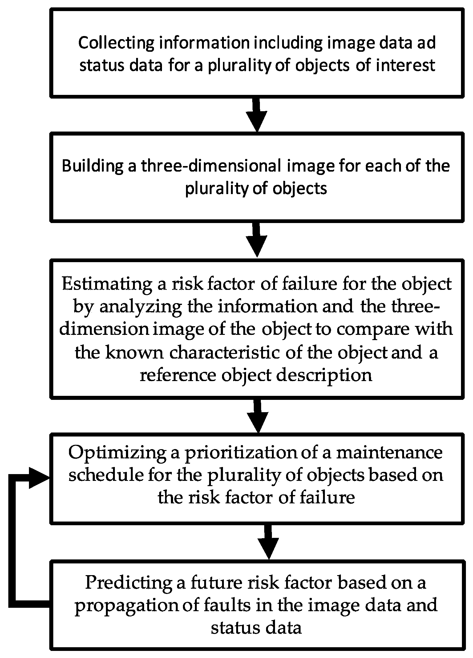
  116. Bojovschi, A.; Rusus, L.I.; Wagner, J.M. System, Method and Computer Program Product for Characterizing Object Status and Determining a Maintenance Schedule. U.S. Patent 20180121845, 2018. [Google Scholar]
Figure 1. The steps that lead to faults related to the electrical stresses of HV insulators.
Applsci 09 00856 g001
Figure 2. Method for analysing the risk of failure of HV insulators leading to substation failure [42].
Applsci 09 00856 g002
Figure 3. Flow chart of a maintenance prioritization method for characterizing insulators [116].
Applsci 09 00856 g003
Table 1. Classification of high-voltage (HV) insulators based on their material content, physical and chemical characteristics and year of implementation.
Insulator Based on Material ContentSpecific CharacteristicsYear of Implementation
Glass insulatorsGood contamination performance due to self-cleaning property
High dielectric strength
Attracts condensation
Easily fractured
1865
Ceramic insulatorsHigh degree of standardization
Outstanding insulating properties
Fairly high electrical and mechanical strength
Self-cleaning property
Heavy
Easily fractured
1880
Composite polymeric insulatorsFairly low degree of standardization
Good hydrophobicity
Self-healing
Prone to mould growth
Good flashover performance
Low cost
High mechanical strength to weight ratio
Lighter in weight
Flexible
1960
Table 2. The size range of typical pollution particles [5].
Nature of Suspended MatterDiameter (µm)
InorganicSmoke0.001–0.3
Fumes0.01–1.0
Dust1.0–100.0
OrganicBacteria1.0–10.0
Plant spores10.0–20.0
Pollen15.0–50.0
WaterFog1.0–50.0
Mist10.0–100.0
Drizzle50.0–400.0
Rain400.0–4000.0
Table 3. The typical pollutants affecting the HV insulators and their sources [37].
ContaminantSource of Pollution
SaltCoastal areas
Salt industries
Salt from snow melting
CementCement plants
Construction sites
FertilisersFertilizer plants
Fertilizers used in cultivated fields
MetallicMining process
CoalCoal handling process
Coal burning/brick-kiln areas
DefecationRoosts of birds
SmogAutomobile emissions at highways and crossings
Diesel engine emissions at railway yards
SmokeWild fire
Industrial burning
Agricultural burning
Table 4. Pollution severity based on the equivalent salt deposition density (ESDD) [38].
ESDD (mg/cm2)Site Severity Based on PollutionLeakage Distance (inch/kVL-G)
<0.01Very light0.87
0.01–0.04Light1.09
0.04–0.15Medium1.37
0.15–0.40Heavy1.70
>0.40Very heavy2.11

