Article

Effect of the Relative Position of the Face Milling Tool towards the Workpiece on Machined Surface Roughness and Milling Dynamics

1
Department of Automated Mechanical Engineering, South Ural State University, 454080 Chelyabinsk, Russia
2
Department of Manufacturing and Materials Engineering, School of Mechanical Engineering, University of Campinas, Campinas 13083-860, Brazil
3
Faculty of Mechanical Engineering and Management, Poznan University of Technology, 60-965 Poznan, Poland
4
Mechanical and Production Engineering, Ahsanullah University of Science and Technology, Dhaka 1208, Bangladesh
5
Faculty of Applied Sciences, University of Campinas, Rua Pedro Zaccaria, Limeira 13484-350, Brazil
6
Department of Civil Engineering, University of Burgos, 09006 Burgos, Spain
7
Faculty of Mechanical Engineering, Opole University of Technology, 76 Proszkowska St., 45-758 Opole, Poland
8
University Center For Research and Development, Chandigarh University, Gharuan, Mohali-140413, Punjab, India
*
Author to whom correspondence should be addressed.
Appl. Sci. 2019, 9(5), 842; https://doi.org/10.3390/app9050842
Submission received: 10 February 2019 / Revised: 20 February 2019 / Accepted: 21 February 2019 / Published: 27 February 2019
(This article belongs to the Section Mechanical Engineering)

Abstract

:
In face milling one of the most important parameters of the process quality is the roughness of the machined surface. In many articles, the influence of cutting regimes on the roughness and cutting forces of face milling is considered. However, during flat face milling with the milling width B lower than the cutter’s diameter D, the influence of such an important parameter as the relative position of the face mill towards the workpiece and the milling kinematics (Up or Down milling) on the cutting force components and the roughness of the machined surface has not been sufficiently studied. At the same time, the values of the cutting force components can vary significantly depending on the relative position of the face mill towards the workpiece, and thus have a different effect on the power expended on the milling process. Having studied this influence, it is possible to formulate useful recommendations for a technologist who creates a technological process using face milling operations. It is possible to choose such a relative position of the face mill and workpiece that will provide the smallest value of the surface roughness obtained by face milling. This paper shows the influence of the relative position of the face mill towards the workpiece and milling kinematics on the components of the cutting forces, the acceleration of the machine spindle in the process of face milling (considering the rotation of the mill for a full revolution), and on the surface roughness obtained by face milling. Practical recommendations on the assignment of the relative position of the face mill towards the workpiece and the milling kinematics are given.

1. Introduction

To manufacture flat surfaces, face milling is widely used as a method of high productivity [1,2,3], and other milling methods [4,5]. At the same time, when describing cutting modes, such as in Guzeev et al. [6], usually there are recommendations about the amount of position symmetry of the cutter and workpiece with asymmetric processing circuits as a range e = (0.03–0.06)B, where B—depth of milling. Moreover, very often cutting tool manufacturing handbooks only contain the processing circuit with position symmetry of the cutter and workpiece, or there is a given displacement range. For example, Coromant [7] recommends using a range; however, there no is specific amount of displacement suggested. The work of Diniz and Filho [8] demonstrated that an asymmetric circuit with an offset close to zero provided for the best tool list. The paper of Bağcı and Aykut [9] proved that the cutting force in milling is lower when using an asymmetric scheme as opposed to symmetrical milling. In reference [10], it is shown that the cutting force is pulsating, which is associated with a variable number of the cutter’s teeth involved in the process that will certainly cause vibrations in a real system.
This is why it is really important to define specific positions of the end of the cutter and the workpiece that provide the minimum roughness of the machined surface.
Today, many publications are dedicated to surface roughness models in face milling [11,12,13,14,15,16,17,18,19,20,21,22,23,24,25,26,27,28]. Baek et al. [11], for the operation conducted as face milling, reported the influence of cutter runout errors on surface quality parameters. They have also investigated the role of changes in the feed rate. Saï and Bouzid [12] optimized cutting parameters for face milling process to optimize the roughness parameter. Muñoz-Escalona and Maropoulos [13] experimentally investigated the effects of machining parameters of face milling responses, such as on the material removal amount, then the performance of tool that served, and the surface roughness parameter. On the other hand, the Taguchi technique was applied by Fratila and Caizar [14] in face milling of Al-Mg alloy. Their target was to maximize the surface quality at the lowest power usage. Considering multiple parameters, Yang et al. [15] performed concurrent optimization of time, cost, and profit. In that problem, the limiting parameters were power, force, speed, feed, and roughness.
Cui et al. [16] conducted an experimental investigation of face milling at two different domains of speed—high and super. They have focused on the machining force, the roughness value of surface, and the chip-morphology. Niu et al. [17] conducted several experiments regarding tool wear study to reveal the tool life, taking into account the surface roughness in milling of TC6 alloy. Conversely, Pimenov [18] formulated the model of height of micro-roughness parameter. In doing so, the author accounted for the wear of tool. Considering the same machining operation but for Inconel 718 superalloy, Tian et al. [19] conducted research to evaluate the influence of machining speed on cutting forces, as well as on tool wear. The study of Pimenov [20] revealed the influence of face mill wear on the surface roughness parameter when the subject material was steel-45. Cui and Zhao [21] studied the machinability of AISI H13 steel, hardened and machined as face milling. The main focus was to observe the behavior of chips, service time of tools, wear mechanism of tools, and quality of surfaces. Also, the comparison was performed based on different conditions. Simunovic et al. [22] considered the cooling-lubrication mode to be an important index to influence the face milling operation. The role of cooling-lubrication was reported alongside the influence of cutting parameters.
In a separate study, the face milling parameters were simulated using FEM (Finite element method) and empirical approach by Cui et al. [23]. The authors’ major concentration was temperature of chips and its morphology, the generated forces, and profile of the machined surface. Their subject job material was AISI H13, machined with CBN (Cubic Boron Nitride) tool. Liu et al. [24] conducted an experimental investigation of high-speed face milling of 17-4PH stainless steel to describe the insert damage process and how it affects surface roughness. Popov and Schindelarz [25] investigated the influence of hydraulic oil that gets into various types of cutting fluids in milling. The stainless steel was machined to examine the tool behavior and roughness attitude.
Kundrák et al. [26] studied the variation in cutting force and surface roughness for face milling resulting from variable magnitudes of cutting parameters. Lopes-da Silva and Hassui [27] studied the effects of tool path along with the process parameters on cutting forces and surface roughness. Yıldırım et al. [28] analyzed the effect of cutting parameters and cooling and lubrication conditions on tool wear and surface roughness when milling on the basis of Waspaloy nickel ceramic tools. However, references [9,10,11,12,13,14,15,16,17,18,19,20,21,22,23,24,25,26,27,28] were not concerned with proposing the optimal position of the face mill and the workpiece that provides the minimum surface roughness.
The following are some examples of papers dedicated to determining surface roughness in face milling using artificial intelligence [29,30,31,32,33,34]. Lela et al. [29] used statistical (i.e., RA (regression analysis)) as well as artificial intelligence (SVR (support vector machines), BNN (Bayesian neural network)) methods to correlate the process variables with surface roughness in face milling. In a separate study, Bajić et al. [30] investigated, in the off-line mode of face milling process control, the roles of input cutting parameters on notable indices, such as roughness, wear, and force in machining. Yalcin et al. [31] made use of a neural network to develop the models of force, roughness, and temperature in respect to process parameters. On the other hand, Kovac et al. [32] used a novel fuzzy approach and regression system to model the responses. Pimenov et al. [33] presented a study that takes tool wear into consideration to predict the surface roughness. This was possible by the use of an artificial intelligence-based approach with an integrated approach of main drive power consideration in real time. Grzenda and Bustillo [34] examined the possibility of using unlabeled data streams to develop prediction models. However, papers [26,27,28,29,30,31,32,33,34] did not describe the optimum position of the face mill and the workpiece that provides the minimum surface roughness either.
Currently, many research studies are dedicated to modeling cutting force in face milling [35,36,37,38,39,40,41,42,43,44,45,46,47]. Kim and Ehmann [35] studied forces in face milling—both static and dynamic type—and developed a method of simulation for them. Young et al. [36] presented a method for predicting cutting forces in face milling using the orthogonal machining theory. Unlike this study, Li et al. [37] took into account the material behavior, conditions of cutting, geometry of the used tools, vibration status, and variations in milling process to model the prediction of forces. Li and Li [38] investigated the true tooth trajectories of a milling cutter and developed a shear length model that accounts for the characteristic wavy surface effects. Baro et al. [39] also investigated cutting forces but considering the use of self-propelling inserts.
Aykut et al. [40], for asymmetric milling, used ANN (artificial neural network) to model the influence of cutting parameters on chip removal process. Pittalà and Monno [41] created a three-dimensional model of the insert geometry in a milling operation using 3D DEFORM™ that proved to be consistent with the empirical data of speed and feed assumed. Guzeev and Pimenov [42] constructed cutting force models that include not only the shear zone processes, but also the constituents of the plowing force [43,44] related to the cutting tool wear. Altinas et al. [45] reviewed the estimates of the cutting geometry of the cutting part and the geometry that are used to predict cutting forces, torque, power and the possibility of vibration and other states of the process along the tool path. Boz et al. [46] experimentally and computationally tested methods for modeling milling of complex triaxial and five-axis examples, as well as for predicting cutting forces. Li and Wang [47] developed a model of cutting forces in milling of hard-to-cut Inconel 718. Despite the fact that many papers take into account the relative positioning of the work-mill [35,36,37,38,39,40,41,42,43,44,45,46,47], none of them are concerned with developing the conditions that ensure the optimum difference between the work-mill which will provide the minimum surface roughness.
The following papers are dedicated to theoretical and experimental studies of face milling processes [48,49,50,51,52,53]. Totis et al. [48] investigated measurement of the cutting force in face milling and proposed a novel rotating dynamometer for this purpose. Rosales et al. [49] focused on applying the novel method of dynamic register cutting forces using predictive statistical methods. Nguyen et al. [50] presented a novel approach to monitoring the spindle title and deflection with the help of HDM (high-definition metrology) surface data. Pimenov [51] developed a mathematical model for the main drive power expended in face milling, taking into consideration the wear of teeth on the back surface of the tool. Ghorbani and Moetakef-Imani [52] investigated full immersion face milling with round inserts and proposed an approach for determining specific cutting force coefficients (SCFCs). Luan et al. [53] structured a predictive model for power in face milling used in the manufacturing processes. However, papers [48,49,50,51,52,53] are not concerned with developing the conditions that ensure the optimum position of the face mill and the workpiece which provides the minimum surface roughness.
A few papers [54,55,56,57,58,59,60] are also dedicated to studying acceleration of vibration in face milling. Lin et al. [54] investigated variable speed cutting as a method for vibration control in face milling. Budak and Altintaş [55,56] proposed in their works an analytical method for predicting vibrations during face milling and implemented an analytical explanation of dynamic phenomena. Seguy et al. [57], in their paper, using the finite element method, performed a dynamic evolution during the milling of a thin-walled part. Mori et al. [58] proposed a novel energy-saving acceleration control method that involves a synchronized state between the acceleration of spindle and the feed unit. Čekić et al. [59] presented the selection of optimal design variety of components integrated in the verbal message system (VBS). Agic et al. [60] studied the effects of radial depth of cut and cutter geometry on cutting forces and vibration amplitudes. Olvera et al. [61], in their article, presented a sustainability analysis for a milling operation with one degree of freedom in a thin-walled workpiece. However, papers [54,55,56,58,59,60,61] are not concerned with developing the conditions that ensure the optimum position of the face mill and the workpiece which provides the minimum surface roughness in addition to acceleration.
The main conclusion of this review is that no previous research seems to have posed the problem of investigating the complex relationship between the relative position of the face mill towards the workpiece, the milling kinematics and the surface roughness, cutting forces, and acceleration of vibrations. While investigating these parameters as a whole, it is planned to provide practical recommendations for technologists on the expediency of using the relative position of the face mill and workpiece and milling kinematics to ensure the minimum roughness of surfaces is obtained by face milling.
The purpose of this study is to investigate the influence of the relative position of the face mill towards the workpiece and milling kinematics on the cutting forces, vibration acceleration, and surface roughness obtained by face milling, and give practical recommendations on the assignment of the relative position of the face mill and workpiece and milling patterns.

2. Materials and Method

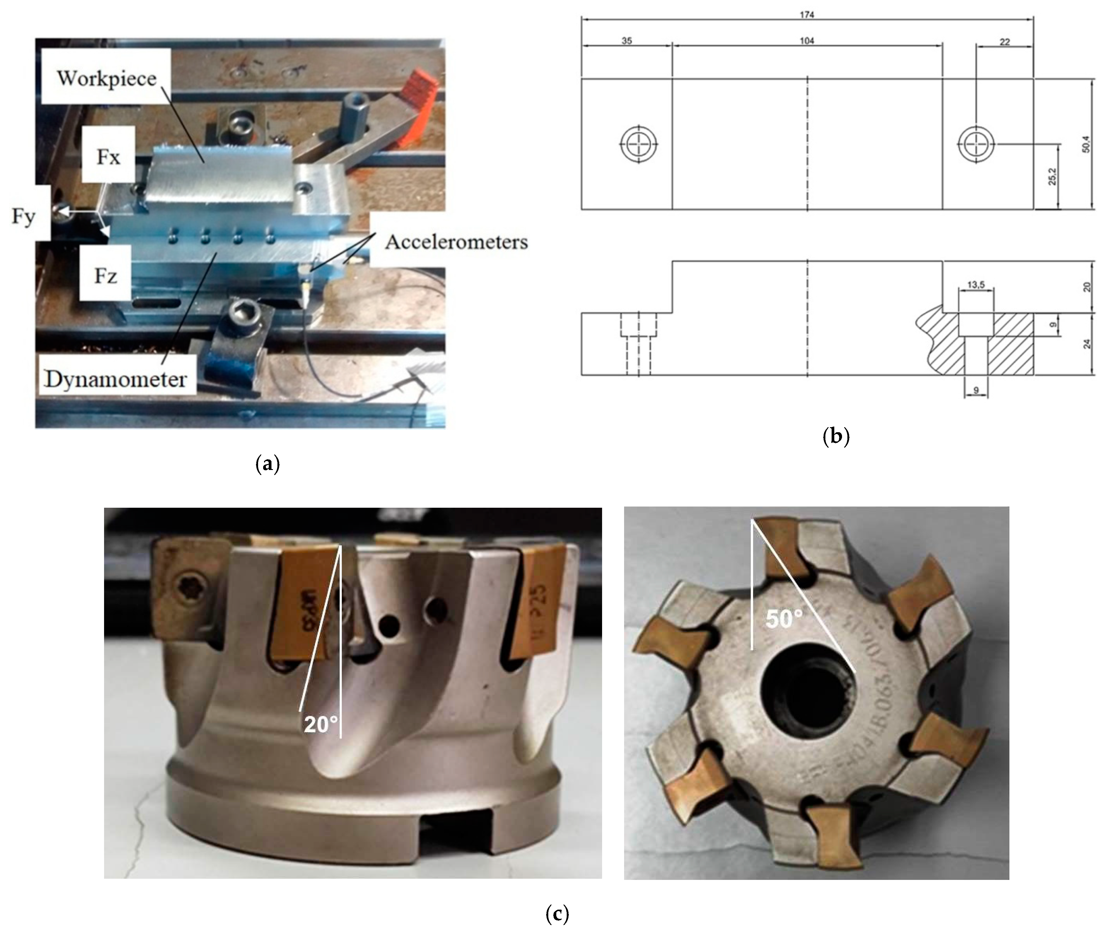
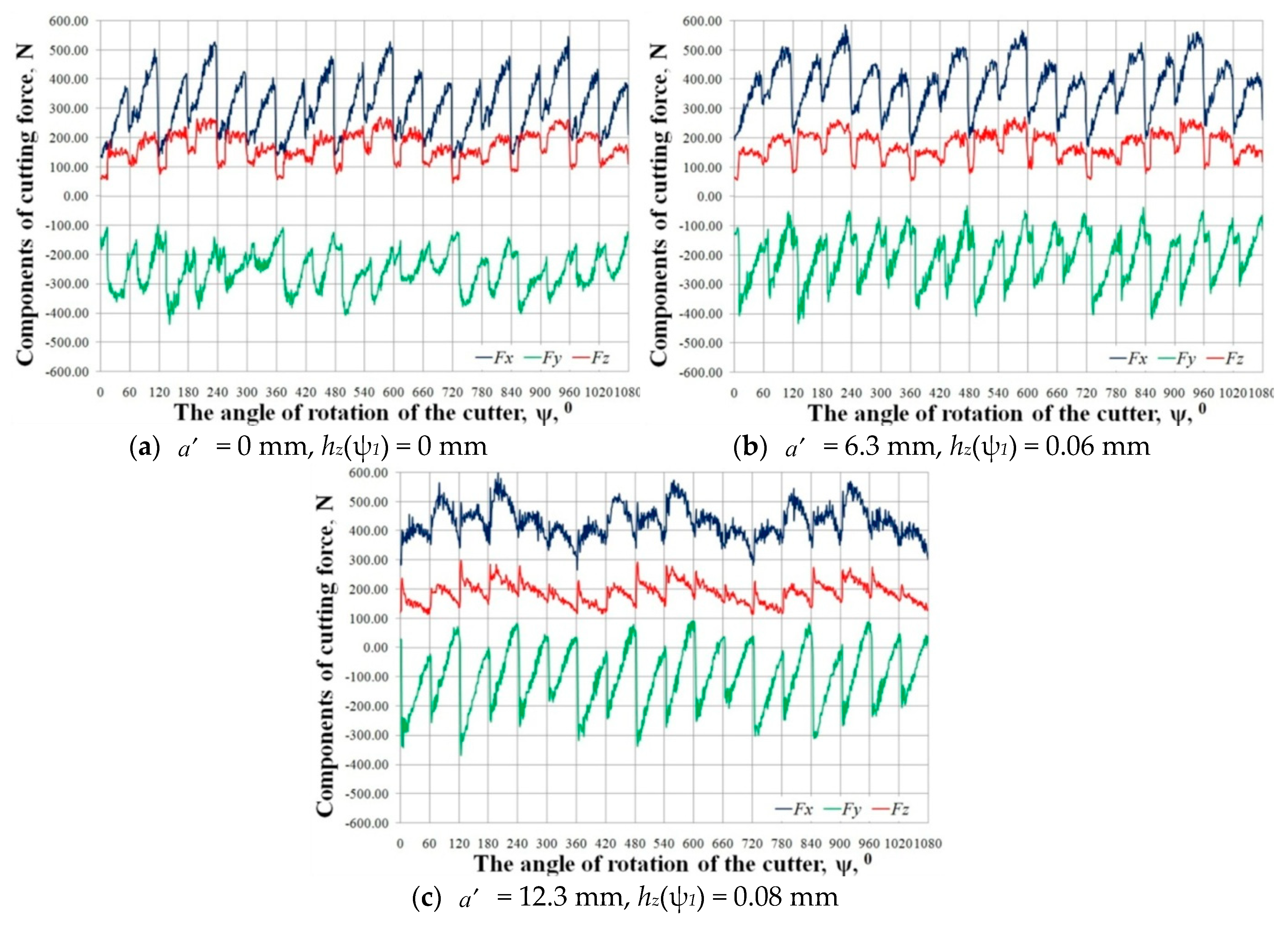
To get actual surface roughness data for the validation of the model attained through artificial intelligence, machining experiments were carried out. Several passes with different milling cutter position ( a ) related to the workpiece were done. During the tests, milling forces (3 directions) and vibrations (2 directions) were acquired. After each pass, the surface roughness was measured.
The experiments were carried out on Mori Seiki SV-40 (Nagoya, Japan), a 3 axis CNC (Computer Numeric Control) vertical machining center with 22 kW of power and a maximum rotational speed of 12,000 rpm. The setup is presented in the Figure 1a; the workpiece and a dynamometer are over the machine tool table, as well as the accelerometers.
The cutting forces were measured using a Kistler 9257BA (Winterthur, Switzerland) stationary dynamometer connected to a Kistler 5019B signal conditioner. After this, a computer with a National Instruments PCI-6025E (Austin, TX, USA) A/D acquisition board and National Instruments LabVIEW 8.5 software were responsible for the acquisition and saving of the force signals. The data acquisition rate was 3 kHz/channel.
The vibrations were measured using accelerometers attached to the workpiece (as shown in Figure 1a). The measurements were conducted in two orthogonal directions (+x and +y in the experiment). At the same time, the signal of acceleration was recorded using Brüel and Kjaer Photon+ (Nærum, Denmark) dynamic signal analyzer. It had 1 kHz sampling rate with default setting for anti-aliasing and phase-distortion filters. The material used for the workpiece was SAE 1045. Its chemical composition is presented in Table 1.
The hardness of the workpiece was established at НV 184 using a Struers (Westlake, OK, USA) Vickers indenter with a load of 30 kgf. The workpiece has the geometry and dimensions presented in Figure 1b. The width of the workpiece was determined according to the milling cutter diameter and the length to fit into the dynamometer. Two screws (M8) were used to attach the workpiece in the dynamometer.
Dry machining tests were carried out using a Walter (Tübingen, Germany) LNGX 130708 R-L55 insert (insert shape rectangular, rake angle 0°, edge length 13 mm, insert width 11 mm, insert thickness 7 mm, tool nose radius 0.8 mm) grade WKP 25 (recommended for machining of steels). The milling cutter, also a Walter (Tübingen, Germany), was a F 4041.B.063.Z06 13. After the indexable inserts were attached to the milling cutter, the tool geometry consisted of the following angles: radial rake angle + 50°, axial rake angle + 20°, clearance angle + 5° in both main and secondary cutting edges, and lead angle 90°. This geometry was chosen because the 90° lead angle tends to generate a higher effort in the plane of the surface being machined. This would increase the trend of vibration and highlight the benefits of the methodology being proposed in the present work. It is worth mentioning that this kind of tool is used in face milling, especially when a 90° shoulder is necessary. The characteristics of the used tools are specified in Table 2. The milling cutter can be seen in Figure 1c.
All cutting conditions used for the face milling operations are specified in Table 3.
For each pass, a new set of inserts was used in order to eliminate tool wear as a variable.
The cutting force and vibrations were acquired during milling in a dynamically stable process. After each pass, the surface roughness was measured three times in the region where the feed per tooth was at its maximum, and 10 mm after the tool entry in the middle part of the workpiece, and 10 mm before the tool exits the workpiece.
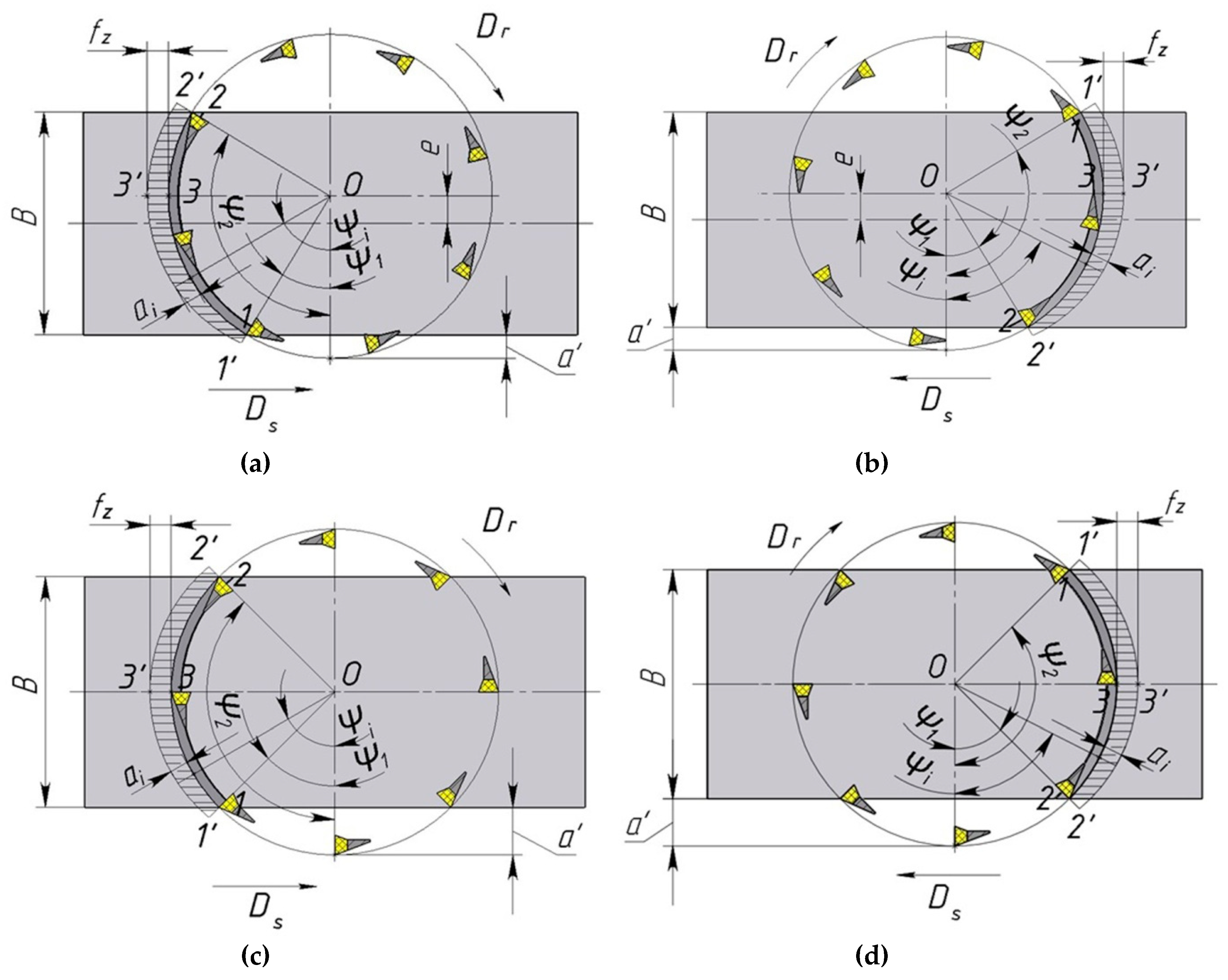
Below in Figure 2a–d, the diagrams are depicted which represent the positions of the cutter and workpiece, described by the a′ factor during the flat face milling, with the milling width B lower than the cutter’s diameter D. The a′ parameter is defined as a translation of cutter’s rotational axis in the direction perpendicular to the feed motion towards the workpiece’s axis of symmetry, parallel to the feed motion. Asymmetric face milling (with positions symmetry of cutter and workpiece in direction that is transverse to feed е, e; positions the end of the cutter diameter and the beginning of the workpiece, a ) is depicted in Figure 2a,b, whereas the symmetric face milling is presented in Figure 2c,d.
Table 4 shows the types of installation of face Up and Down milling.
Note that a = 0 mm means that e = 12.6/2 = 6.3 mm and when a = 12.6 mm then e = −12.6/2 = −6.3 mm.
We show the formulas for calculating the parameters given in the table.
Inlet angle:
ψ 1 = arccos ( B + 2 e D )
Out angle:
ψ 2 = arccos ( 2 e B D )
In Equations (1) and (2), B is the depth of milling; D is diameter of milling; e is relative positions symmetry of cutter and workpiece.
Through the e = R a B / 2 , correlations (see Figure 2) and Equations (1) and (2) are converted to the form shown in Equations (3) and (4), respectively.
The contact angle of a face mill with the workpiece ψ generally is determined:
ψ = ψ 2 ψ 1
The angle between adjacent teeth would be multiple to the contact angle (see Figure 2).
θ = 2 π / z ,
where π = 3.14159, …, i.e., Pi number—a mathematical constant that expresses the ratio of circumference to its diameter length [38].
The number of active teeth involved in the work is determined by the formula:
z c = ψ / θ ,
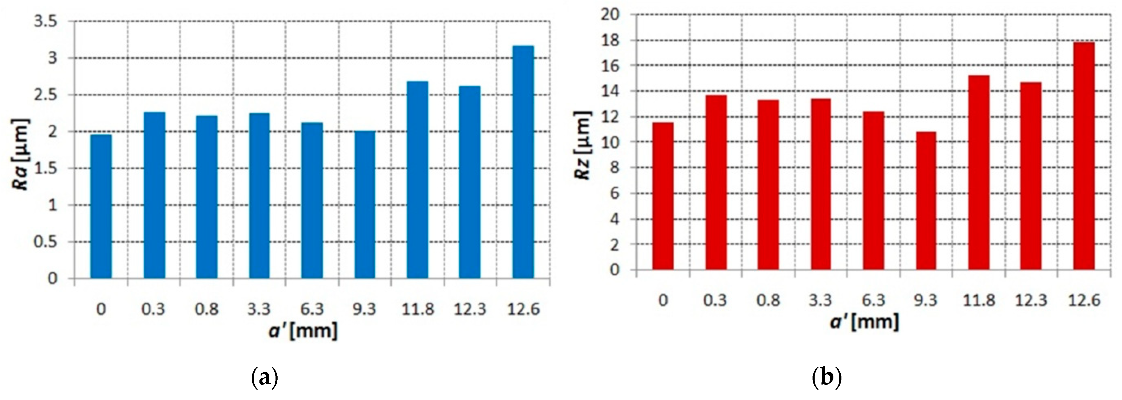
Table 5 shows the experimental values of the roughness of the surfaces Ra and Rz (for four runs and average values) for different values of the relative position of the face mill and workpiece a′.
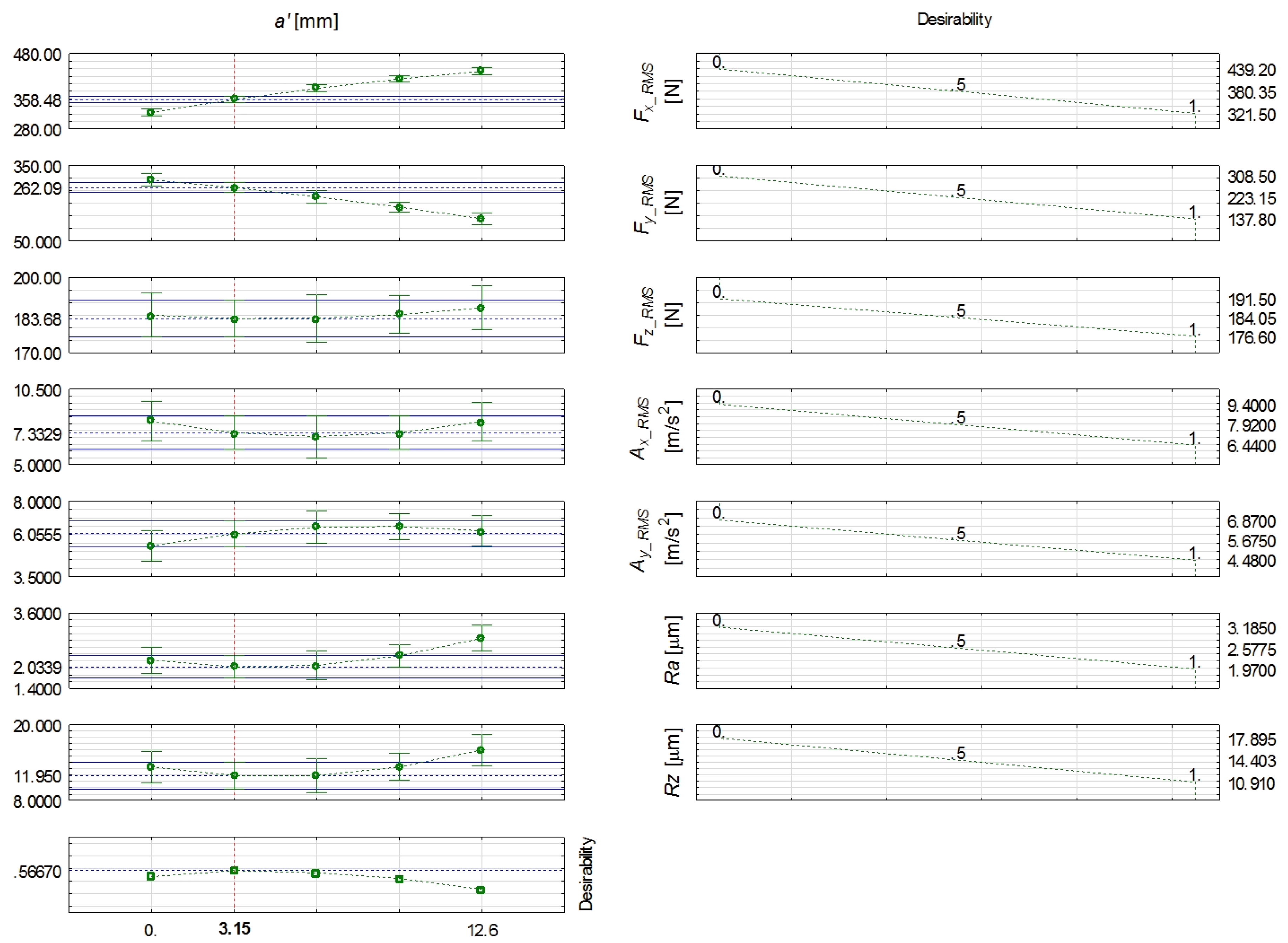
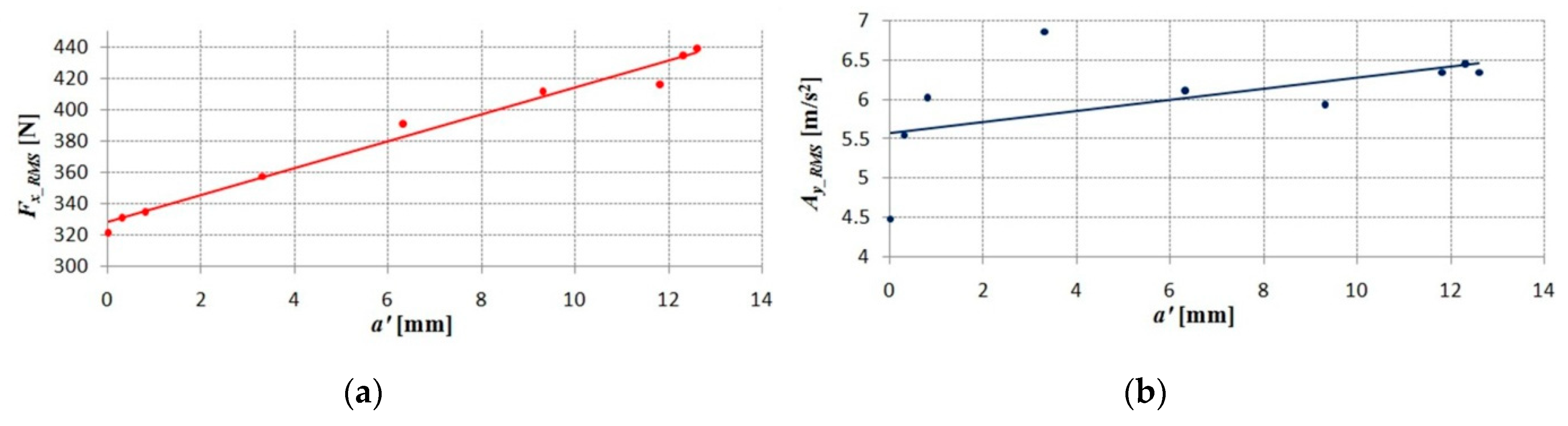
Table 6 shows the experimental components of the cutting forces Fx, Fy, Fz (minimum, maximum, average, and RMS (Root-mean-square)) and accelerations of vibrations ax and ay (RMS) for different values of relative position of face mill and workpiece, a′.

3. Results and Discussion

3.1. Evaluation of Dynamics and Surface Roughness

During the face milling experiments with various radial immersions (defined by the a factor), the number of active teeth was contained within the range zc = 1.77 ÷ 2.11. This indicates that in the milling process, 1 to 3 teeth, depending on tool rotational angle and selected radial immersion, are engaged simultaneously. The non-integer values of zc denote that in the milling process, the number of teeth engaged in the cutting is variable, which in its turn causes variations in maximal chip cross-sections per the consecutive teeth, and thus the changes in cutting force peak values per teeth (see Figure 3a–c). On the other hand, the variations in cutting force peak values can be also induced by the geometrical errors of the machine-toolholder-tool system (manifesting in axial run out), which contributes to the changes in real values of axial depths of cut per consecutive tooth.
Figure 3a–c show also that independently on selected radial immersion, the feed Fy, and feed normal force Fx components’ absolute values are significantly higher than thrust force Fy values. It should be noted that Fy and Fx components are directly correlated with milling kinematics and the chip decohesion process. On the other hand, the thrust force is only marginally dependent on chip formation mechanisms, and its value is strictly correlated with the rubbing and ploughing mechanisms occurring between the tool’s flank face and the machined surface. Thus, the potential growth of thrust force could be attributed to the relatively high friction coefficient between the workpiece and the tool flank face, as well as to the progressing tool wear.
All face milling tests were carried out with constant axial depths of cut d and milling width B. Thus, the cutting force values should be comparable, independent of selected radial immersions. Nevertheless, some differences in cutting force absolute values are found between the tested a factors. Figure 3 shows that absolute values of cutting force components in the case of milling with a = 0 mm are lower than those reached during machining with a = 6.3 mm and a = 12.3 mm. These differences can be explained by the various initial uncut chip thicknesses ai1) found for different a values. The ai1) corresponds to the uncut chip thickness during the initial contact of the tooth with the workpiece. The growth of a values induces the increase of ai1). When the a = 0 mm, the ai1) = 0 mm, and the growth of chip cross section (and thus cutting forces) is gradual. However, in the case of a = 6.3 mm, the ai1) = 0.06 mm, and when a = 12.3 mm, the ai1) = 0.08 mm. This reveals that initiation of chip formation during machining with higher a values occurs at relatively high uncut chip thicknesses, and thus the impact of the cutting tooth on the workpiece can cause some forced vibrations, contributing to the growth of cutting force dynamic components. These relations can be also found for the root mean square (RMS) values of Fx force in the function of a (Figure 4a), i.e., the growth of a factor leads to the increase in force. This means that the Fx force component is strongly affected by milling dynamics. In order to further analyze these findings, the RMS values of accelerations of vibrations in the function of a have been determined (see Figure 4b). It can be observed that in the case of vibrations in Y direction, the increasing trend together with the a factor is found, which can be attributed to the relations between the initial uncut chip thicknesses ai1) and forced vibrations in milling.
In case of surface roughness parameters (Figure 5a,b), the increasing trend with the growth of a is found. However, local oscillations of these values, mainly in the range of 0 ≤ a ≤ 6.3 mm, can be observed. The highest values of Ra and Rz parameters occur for the a = 12.6 mm, which also corresponds to the highest measured values of Fx force and Ay accelerations of vibrations. Therefore, the correlation between the formation of surface roughness and process dynamics can be exposed. Nevertheless, during the face milling process, the formation of the surface profile can be also strongly affected by geometrical errors in the machine-toolholder-tool system, plastic and elastic deformations of the material being cut, homogeneity of the workpiece, as well as some random factors.

3.2. Multicriteria Optimization of Face Milling.

In practical applications, the choice of milling parameters is crucial in providing the production efficiency, surface finish, tool life, as well as to minimize the load during the machining process. This effect can be achieved with a multicriteria optimization method. In our research, the relative position of the tool and workpiece defined by a factor has been applied as the parameter subjected to optimization. The proposed optimization method included the conversion of the approximated output measures to the singular value of the total desirability Dtot. Therefore, the problem of concurrent optimization of numerous output quantities has been reduced to the obtainment of 1 output measure, which leads to the maximization of the total response desirability. The optimization procedure has been carried out in Statistica 13 software.
The following optimization criteria were adopted:
  • Root mean square values of cutting forces (Fx, Fy, Fz);
  • Root mean square values of acceleration of vibration components (Ax, Ay);
  • Surface roughness parameters (Ra, Rz).
Firstly, the machining tests were carried out based on the central composite experimental design. Subsequently, the response desirability profile has been defined for the examined output quantities. In this part, all outputs were assigned to the partial desirability functions (D(Fx), D(Fy), D(Fz), D(Ax), D(Ay), D(Ra), D(Rz)), the values of which were contained in the range <0, 1>. Therefore, the response desirability profiles for the outputs were obtained on the basis of the expressions shown in Equations (6)–(33):
F x 322 N D ( F x ) = 1
322   N < F x 380   N     0.5 D ( Fx ) < 1
380   N < F x < 439   N     0 < D ( F x ) < 0.5
F x 439   N     D ( Fx ) = 0
F y 138 N     D ( Fy ) = 1
138   N < F y 223   N     0.5 D ( Fy ) < 1
223   N < F y < 308   N     0 < D ( F y ) < 0.5
F y 308   N     D ( Fy ) = 0
F z 176 N D ( Fz ) = 1
176   N < F z 184   N     0.5 D ( Fz ) < 1
184   N < F z < 191   N     0 < D ( F z ) < 0.5
F z 191   N     D ( Fz ) = 0
A x 6.4   m / s 2 D ( Ax ) = 1
6.4   m / s 2 < A x 7.9   m / s 2     0.5 D ( Ax ) < 1
7.9   m / s 2 < A x < 9.4   m / s 2     0 < D ( A x ) < 0.5
A x 9.4   m / s 2     D ( Ax ) = 0
A y 4.5   m / s 2 D ( Ay ) = 1
4.5   m / s 2 < A y 5.7   m / s 2     0.5 D ( Ay ) < 1
5.7   m / s 2 < A y < 6.9   m / s 2     0 < D ( A y ) < 0.5
A y 6.9   m / s 2     D ( Ay ) = 0
Ra 1.97   µ m   D ( Ra ) = 1
1.97   µ m < R a 2.58   µ m     0.5 D ( Ra ) < 1
2.58   µ m < R a < 3.19   µ m     0 < D ( R a ) < 0.5
Ra 3.19   µ m     D ( Ra ) = 0
Rz 10.9   µ m   D ( Rz ) = 1
10.9   µ m < R z 14.4   µ m     0.5 D ( Rz ) < 1
14.4   µ m < R z < 17.9   µ m     0 < D ( R z ) < 0.5
Rz 17.9   µ m     D ( Rz ) = 0
The partial desirabilities acquire the values between 0 and 1. In the case of the least satisfying result of the experiment (e.g., the measured force, surface roughness parameter values, etc.), the value of partial desirability is equal to 0. Contrarily, in the case where the result of the experiment is the most desirable, the partial desirability reaches 1. Thus, in the current approach, the highest partial desirability values were allocated to the lowest values of measured forces, vibrations, and surface roughness parameters in the whole conducted experiment (see Equations (6), (10), (14), (18, (22), (26), and (30)). On the other hand, when the less desirable effect has been reached (e.g., the highest values of measured forces, vibrations, and surface roughness parameters), partial desirabilities were equal to 0 (Equations (9), (13), (17), (21), (25), (29), and (33)). Partial desirability equal to 0.5 indicates a moderate effect of the process. Therefore, in the current approach, the median values of the measured quantities in the whole investigated range corresponded to a partial desirability equal to 0.5.
In the next stage, the search for the optimum solution procedure has been employed. This task involved the mesh definition of the input variable a . After that, the predictive values of output factors have been derived for the whole range of mesh points. It resulted in the obtainment of partial desirability values. The partial desirability mean geometric values were derived in each mesh point in order to determine the total desirability value. Finally, the optimal solution searching algorithm was employed. The application of this algorithm enables the acquisition of the input factor value ( a _opt) matching with the maximal value of the total desirability. The optimal solution searching algorithm is based on the simplex method.
Figure 6 depicts the values of partial and total desirability. The total desirability chart characterizes the relations between the a and simultaneous effect of all investigated quantities. It can be concluded from this chart that the optimal relative position of the tool and the workpiece is equal to a _opt = 3.15 mm. The face milling process with the selection of a _opt enables the obtainment of total desirability at the level of 0.57. This means that simultaneous achievement of the lowest response values is not possible with the application of a _opt. However, during face milling with a _opt = 3.15 mm, the cutting force components’ RMS values will not exceed 360 N for the Fx, 265 N for the Fy, and 185 N for the Fz. The acceleration of vibration RMS values will not exceed 7.3 m/s2 for the Ax and 6 m/s2 for the Ay. Moreover, the surface roughness parameters will be at most 2 µm for the Ra and 12 µm for the Rz.
The results presented above reveal that the face milling process with B < D is affected not only by the selected values of cutting parameters, but also by the relative position between the tool and the workpiece a . This geometrical parameter is independent of axial depth of cut and feed but characterizes the active number of teeth, and thus the variations in areas of cut. Therefore, it affects the process dynamics and surface finish. The conducted research shows that the influence of a on process outputs is not described by a monotonic relation. However, the conducted multi-criteria optimization identifies the optimal value of a , which can contribute to improvements of the machined surface finish in a range of dynamically stable milling conditions.

4. Conclusions

The work was focused on an analysis of the influence of the relative position of the face mill towards the workpiece on the milling dynamics and technological effects of the process. The conducted research revealed the following conclusions:
(1)
The changes in radial immersion of the face mill towards the workpiece, described by the a factor, despite the selected constant values of axial depths of cut ap and milling widths B, affect the active number of teeth engaged in the workpiece. Consequently, it leads to the variations in maximal instant forces per consecutive teeth and can affect the milling vibration values and surface roughness.
(2)
The value of a factor directly characterizes the face milling process kinematics. The growth of a value reduces the contribution of up milling kinematics in the whole face milling process towards the contribution of down milling. Conducted studies clearly show that in the case of a = 0 (predominantly up milling), the lowest forces (in X and Z directions) and vibrations (in Y direction) are reached, which is attributed to the gradual immersion of the tool into the workpiece (and thus the gradual increase of uncut chip thickness in function of tool rotation angle).
(3)
Initiation of chip formation during face milling with higher a values occurs at relatively high uncut chip thicknesses. Therefore, the dynamic contact between the tooth and workpiece can cause some forced vibrations, contributing to the growth of cutting force dynamic components. This relation has been confirmed by measurements of vibrations, which revealed the increasing trend of acceleration of vibration in Y direction together with the growth of a factor.
(4)
The performed multicriteria optimization, based on determination of total desirability function, enabled the obtainment of optimal a factor, and equaled to 3.15 mm. The face milling with the selection of optimal a factor affects the reduction of cutting forces, vibrations, and surface roughness parameters. Therefore, these findings can be implemented in industrial applications. To put this another way, the selection of optimal tool radial immersion towards the workpiece a _opt during flat face milling with the milling width B lower than the cutter’s diameter D can contribute to improvements in process economics (resulting from the reduction of surface roughness and milling power).

Author Contributions

Conceptualization, D.Y.P., A.H., and S.W.; methodology, D.Y.P., A.H., and S.W.; software, A.H., A.M., S.W., and D.I.S.; validation, A.H., A.M., and D.I.S.; formal analysis, A.H., A.M., S.W., and D.I.S.; investigation, A.H., A.M., S.W., and D.I.S.; resources, A.H., A.M., S.W., and D.I.S.; data curation, A.H., A.M., S.W., and D.I.S.; writing—original draft preparation, D.Y.P., A.H., S.W., M.M., A.M., D.I.S., A.B., G.K., and M.K.G.; writing—review and editing, D.Y.P., A.H., S.W., M.M., A.M., D.I.S., A.B., G.K., and M.K.G.; visualization, A.H., A.M., S.W., and D.I.S.; supervision, D.Y.P., S.W., M.M., M.K.G., G.K., and M.K.G.; project administration, D.Y.P. and A.H.; funding acquisition, D.Y.P. and A.H.

Funding

The study was supported under Act 211 Government of the Russian Federation, contract Nr. 02.A03.21.0011.

Conflicts of Interest

The authors declare no conflict of interest.

Nomenclature

RaArithmetic average value of surface roughness (µm)
RzMean surface roughness depth parameter (µm)
DCutter diameter (mm)
krMajor cutting edge angle (deg)
zNumber of teeth
dDepth of cut (mm)
vcCutting speed (m/min)
fzFeed per tooth (mm/tooth)
aRelative position of the face mill towards the workpiece (mm)
eDisplacement of the cutter axis towards the workpiece (mm)
aiInstant uncut chip thickness (mm)
ψ1, ψinInlet angle (deg)
ψ2, ψoutOut angle (deg)
ψThe contact angle (deg)
θTooth spacing angle (deg)
ψiAngular coordinate of the i-th tooth (deg)
BMilling width (mm)
DrDirection of rotary motion
DsFeed movement
Fx, Fy, FzComponents of the cutting forces (N)
Ax,AyAccelerations of vibrations (m/s2)

References

  1. Karkalos, N.E.; Galanis, N.I.; Markopoulos, A.P. Surface roughness prediction for the milling of Ti-6Al-4V ELI alloy with the use of statistical and soft computing techniques. Measurement 2016, 90, 25–35. [Google Scholar] [CrossRef]
  2. JersákJ, F.; Kaplan, K. Comparison of the influence of process fluids on tool life in face milling. Manuf. Technol. 2015, 15, 977–984. [Google Scholar]
  3. Pimenov, D.Y.; Guzeev, V.I.; Krolczyk, G.; Mia, M.; Wojciechowski, S. Modeling flatness deviation in face milling considering angular movement of the machine tool system components and tool flank wear. Precis. Eng. 2018, 54, 327–337. [Google Scholar] [CrossRef]
  4. De Lacalle, L.N.L.; Rodriguez, A.; Lamikiz, A.; Celaya, A.; Alberdi, R. Five-axis machining and burnishing of complex parts for the improvement of surface roughness. Mater. Manuf. Proces. 2011, 26, 997–1003. [Google Scholar] [CrossRef]
  5. López de Lacalle, L.N.; Lamikiz, A.; Salgado, M.A.; Herranz, S.; Rivero, A. Process planning for reliable high-speed machining of moulds. Int. J. Prod. Res. 2002, 40, 2789–2809. [Google Scholar] [CrossRef]
  6. Guzeev, V.I.; Batuev, V.A.; Surkov, I.V. Cutting Conditions for Turning and Milling and Boring Machines with Numerical Control: Handbook; Mashinostroeniye: Moscow, Russia; p. 368.
  7. Sandvik Coromant. Available online: http://www.sandvik.coromant.com (accessed on 25 February 2019).
  8. Diniz, A.E.; Filho, J.C. Influence of the relative positions of tool and workpiece on tool life, tool wear and surface finish in the face milling process. Wear 1999, 232, 67–75. [Google Scholar] [CrossRef]
  9. Bağcı, E.; Aykut, Ş. The Effects of Tool Position, Coating and Cutting Parameters on Forces, Power, MRR and Wear in Face Milling of Stellite 6. Arab. J. Sci. Eng. 2014, 39, 8135–8146. [Google Scholar] [CrossRef]
  10. Nguyen, H.T.; Wang, H.; Hu, S.J. Characterization of cutting force induced surface shape variation in face milling using high-definition metrology. J. Manuf. Sci. Eng. Trans. ASME 2013, 135, 041014. [Google Scholar] [CrossRef]
  11. Baek, D.K.; Ko, T.J.; Kim, H.S. Optimization of feed rate in a face milling operation using a surface roughness model. Int. J. Mach. Tool. Manuf. 2001, 41, 451–462. [Google Scholar] [CrossRef]
  12. Saï, K.; Bouzid, W. Roughness modeling in up-face milling. Int. J. Adv. Manuf. Technol. 2005, 26, 324–329. [Google Scholar] [CrossRef]
  13. Muñoz-Escalona, P.; Maropoulos, P. Integrated optimisation of surface roughness and tool performance when face milling 416 SS. Int. J. Comput. Integ. Manuf. 2010, 23, 248–256. [Google Scholar] [CrossRef]
  14. Fratila, D.; Caizar, C. Application of Taguchi method to selection of optimal lubrication and cutting conditions in face milling of AlMg3. J. Clean. Prod. 2011, 19, 640–645. [Google Scholar] [CrossRef]
  15. Yang, W.-A.; Guo, Y.; Liao, W. Multi-objective optimization of multi-pass face milling using particle swarm intelligence. Int. J. Adv. Manuf. Technol. 2011, 56, 429–443. [Google Scholar] [CrossRef]
  16. Cui, X.; Zhao, J.; Jia, C.; Zhou, Y. Surface roughness and chip formation in high-speed face milling AISI H13 steel. Int. J. Adv. Manuf. Technol. 2012, 61, 1–13. [Google Scholar] [CrossRef]
  17. Niu, Q.; Chen, M.; Ming, W.; An, Q. Evaluation of the performance of coated carbide tools in face milling TC6 alloy under dry condition. Int. J. Adv. Manuf. Technol. 2013, 64, 623–631. [Google Scholar] [CrossRef]
  18. Pimenov, D.Yu. Geometric model of height of microroughness on machined surface taking into account wear of face mill teeth. J. Frict. Wear. 2013, 34, 290–293. [Google Scholar] [CrossRef]
  19. Tian, X.; Zhao, J.; Zhao, J.; Gong, Z.; Dong, Y. Effect of cutting speed on cutting forces and wear mechanisms in high-speed face milling of Inconel 718 with Sialon ceramic tools. Int. J. Adv. Manuf. Technol. 2013, 69, 2669–2678. [Google Scholar] [CrossRef]
  20. Pimenov, D.Y. Experimental research of face mill wear effect to flat surface roughness. J. Frict. Wear. 2014, 35, 250–254. [Google Scholar] [CrossRef]
  21. Cui, X.; Zhao, J. Cutting performance of coated carbide tools in high-speed face milling of AISI H13 hardened steel. Int. J. Adv. Manuf. Technol. 2014, 71, 1811–1824. [Google Scholar] [CrossRef]
  22. Simunovic, K.; Simunovic, G.; Saric, T. Single and multiple goal optimization of structural steel face milling process considering different methods of cooling/lubricating. J. Clean. Prod. 2015, 94, 321–329. [Google Scholar] [CrossRef]
  23. Cui, X.; Guo, J.; Zhao, J.; Yan, Y. Chip temperature and its effects on chip morphology, cutting forces, and surface roughness in high-speed face milling of hardened steel. Int. J. Adv. Manuf. Technol. 2015, 77, 2209–2219. [Google Scholar] [CrossRef]
  24. Liu, G.; Zou, B.; Huang, C.; Wang, X.; Wang, J.; Liu, Z. Tool damage and its effect on the machined surface roughness in high-speed face milling the 17-4PH stainless steel. Int. J. Adv. Manuf. Technol. 2016, 83, 257–264. [Google Scholar] [CrossRef]
  25. Popov, A.; Schindelarz, R. Effect of hydraulic oil entering the cutting fluid on the tool life and roughness in milling of stainless steel. Manuf. Technol. 2017, 17, 364–369. [Google Scholar]
  26. Kundrák, J.; Gyáni, K.; Felho, C.; Deszpoth, I. The effect of the shape of chip cross section on cutting force and roughness when increasing feed in face milling. Manuf. Technol. 2017, 17, 335–342. [Google Scholar]
  27. Lopes da Silva, R.H.; Hassui, A. Cutting force and surface roughness depend on the tool path used in side milling: An experimental investigation. Int. J. Adv. Manuf. Technol. 2018, 96, 1445–1455. [Google Scholar] [CrossRef]
  28. Yıldırım, Ç.V.; Kıvak, T.; Erzincanlı, F. Tool wear and surface roughness analysis in milling with ceramic tools of Waspaloy: A comparison of machining performance with different cooling methods. J. Braz. Soc. Mech. Sci. Eng. 2019, 41, 83. [Google Scholar] [CrossRef]
  29. Lela, B.; Bajić, D.; Jozić, S. Regression analysis, support vector machines, and Bayesian neural network approaches to modeling surface roughness in face milling. Int. J. Adv. Manuf. Technol. 2009, 42, 1082–1088. [Google Scholar] [CrossRef]
  30. Bajić, D.; Celent, L.; Jozić, S. Modeling of the influence of cutting parameters on the surface roughness, tool wear and cutting force in face milling in off-line process control. Stroj. Vestn. / J. Mech. Eng. 2012, 58, 673–682. [Google Scholar] [CrossRef]
  31. Yalcin, U.; Karaoglan, A.D.; Korkut, I. Optimization of cutting parameters in face milling with neural networks and taguchi based on cutting force, surface roughness and temperatures. Int. J. Prod. Res. 2013, 51, 3404–3414. [Google Scholar] [CrossRef]
  32. Kovac, P.; Rodic, D.; Pucovsky, V.; Savkovic, B.; Gostimirovic, M. Application of fuzzy logic and regression analysis for modeling surface roughness in face milliing. J. Intellig. Manuf. 2013, 24, 755–762. [Google Scholar] [CrossRef]
  33. Pimenov, D.Yu.; Bustillo, A.; Mikolajczyk, T. Artificial intelligence for automatic prediction of required surface roughness by monitoring wear on face mill teeth. J. Intellig. Manuf. 2018, 29, 1045–1061. [Google Scholar] [CrossRef]
  34. Grzenda, M.; Bustillo, A. Semi-supervised roughness prediction with partly unlabeled vibration data streams. J. Intellig. Manuf. 2019, 30, 933–945. [Google Scholar] [CrossRef]
  35. Kim, H.S.; Ehmann, K.F. A cutting force model for face milling operations. Int. J. Mach. Tool. Manuf. 1993, 333, 651–673. [Google Scholar] [CrossRef]
  36. Young, H.-T.; Mathew, P.; Oxley, P.L.B. Predicting cutting forces in face milling. Int. J. Mach. Tool. Manuf. 1994, 34, 771–783. [Google Scholar] [CrossRef]
  37. Li, X.P.; Zheng, H.Q.; Wong, Y.S.; Nee, A.Y.C. An approach to theoretical modeling and simulation of face milling forces. J. Manuf. Process. 2000, 2, 225–240. [Google Scholar] [CrossRef]
  38. Li, H.Z.; Li, X.P. Milling force prediction using a dynamic shear length model. Int. J. Mach. Tool. Manuf. 2002, 42, 277–286. [Google Scholar] [CrossRef]
  39. Baro, P.K.; Joshi, S.S.; Kapoor, S.G. Modeling of cutting forces in a face-milling operation with self-propelled round insert milling cutter. Int. J. Mach. Tool. Manuf. 2005, 45, 831–839. [Google Scholar] [CrossRef]
  40. Aykut, S.; Gölcü, M.; Semiz, S.; Ergür, H.S. Modeling of cutting forces as function of cutting parameters for face milling of satellite 6 using an artificial neural network. J. Mater. Process. Technol. 2007, 190, 199–203. [Google Scholar] [CrossRef]
  41. Pittalà, G.M.; Monno, M. 3D finite element modeling of face milling of continuous chip material. Int. J. Adv. Manuf. Technol. 2010, 47, 543–555. [Google Scholar] [CrossRef]
  42. Guzeev, V.I.; Pimenov, D.Yu. Cutting force in face milling with tool wear. Russ. Eng. Res. 2011, 31, 989–993. [Google Scholar] [CrossRef]
  43. Pimenov, D.Yu.; Guzeev, V.I. Mathematical model of plowing forces to account for flank wear using FME modeling for orthogonal cutting scheme. Int. J. Adv. Manuf. Technol. 2017, 89, 3149–3159. [Google Scholar] [CrossRef]
  44. Pimenov, D.Yu.; Guzeev, V.I.; Koshin, A.A. Influence of cutting conditions on the stress at tool’s rear surface. Russ. Eng. Res. 2011, 31, 1151–1155. [Google Scholar] [CrossRef]
  45. Altintas, Y.; Kersting, P.; Biermann, D.; Budak, E.; Denkena, B.; Lazoglu, I. Virtual process systems for part machining operations. CIRP Ann. Manuf. Technol. 2014, 63, 585–605. [Google Scholar] [CrossRef]
  46. Boz, Y.; Erdim, H.; Lazoglu, I. A comparison of solid model and three-orthogonal dexelfield methods for cutter-workpiece engagement calculations in three- and five-axis virtual milling. Int. J. Adv. Manuf. Technol. 2015, 81, 811–823. [Google Scholar] [CrossRef]
  47. Li, H.Z.; Wang, J. A cutting forces model for milling Inconel 718 alloy based on a material constitutive law. Proc. Inst. Mech. Eng. Pt. C-J. Mech. Eng. Sci. 2013, 227, 1761–1775. [Google Scholar] [CrossRef]
  48. Totis, G.; Wirtz, G.; Sortino, M.; Veselovac, D.; Kuljanic, E.; Klocke, F. Development of a dynamometer for measuring individual cutting edge forces in face milling. Mech. Syst. Signal. Process. 2010, 24, 1844–1857. [Google Scholar] [CrossRef]
  49. Rosales, A.; Vizán, A.; Alanís, A. Modeling and prediction of cutting forces using a dynamic register cutting forces in face milling processes. Eur. J. Sci. Res. 2012, 67, 260–271. [Google Scholar]
  50. Nguyen, H.T.; Wang, H.; Hu, S.J. Modeling cutter tilt and cutter-spindle stiffness for machine condition monitoring in face milling using high-definition surface metrology. Int. J. Adv. Manuf. Technol. 2014, 70, 1323–1335. [Google Scholar] [CrossRef]
  51. Pimenov, D.Y. Mathematical modeling of power spent in face milling taking into consideration tool wear. J. Frict. Wear 2015, 36, 45–48. [Google Scholar] [CrossRef]
  52. Ghorbani, H.; Moetakef-Imani, B. Specific cutting force and cutting condition interaction modeling for round insert face milling operation. Int. J. Adv. Manuf. Technol. 2016, 84, 1705–1715. [Google Scholar] [CrossRef]
  53. Luan, X.; Zhang, S.; Li, G. Modified power prediction model based on infinitesimal cutting force during face milling process. Int. J. Precis. Eng. Manuf. Green Technol. 2018, 5, 71–80. [Google Scholar] [CrossRef]
  54. Lin, S.C.; DeVor, R.E.; Kapoor, S.G. Effects of variable speed cutting on vibration control in face milling. J. Eng. Ind. 1990, 112, 1–11. [Google Scholar] [CrossRef]
  55. Budak, E.; Altintaş, Y. Analytical prediction of chatter stability in milling—Part I: General formulation. J. Dyn. Sys. Meas. Control 1998, 120, 22–30. [Google Scholar] [CrossRef]
  56. Budak, E.; Altintaş, Y. Analytical prediction of chatter stability in milling—Part II: Application of the general formulation to common milling systems. J. Dyn. Sys. Meas. Control 1998, 120, 31–36. [Google Scholar] [CrossRef]
  57. Seguy, S.; Campa, F.J.; de Lacalla, L.N.L.; Arnaud, L.; Dessein, G.; Aramendi, G. Toolpath dependent stability lobes for the milling of thin-walled parts. Int. J. Mach. Mach. Mater. 2008, 4, 377–392. [Google Scholar] [CrossRef]
  58. Mori, M.; Fujishima, M.; Inamasu, Y.; Oda, Y. A study on energy efficiency improvement for machine tools. CIRP Ann. Manuf. Technol. 2011, 60, 145–148. [Google Scholar] [CrossRef]
  59. Čekić, A.; Begić-Hajdarević, D.; Kulenović, M. Effect of the cutting parameters on cutting forces in high speed face milling | [Utjecaj parametara obrade na sile rezanja pri visokobrzinskom Čeonom glodanju]. Teh. Vjesn. 2013, 20, 775–780. [Google Scholar]
  60. Agic, A.; Eynian, M.; Hägglund, S.; Ståhl, J.-E.; Beno, T. Influence of radial depth of cut on entry conditions and dynamics in face milling application. J. Superhard. Mater. 2017, 39, 259–270. [Google Scholar] [CrossRef]
  61. Olvera, D.; Urbikain, G.; Elías-Zuñiga, A.; López de Lacalle, L.N. Improving stability prediction in peripheral milling of Al7075T6. Appl. Sci. 2018, 8, 1316. [Google Scholar] [CrossRef]
Figure 1. Experimental part: (a) Experimental setup, (b) workpiece specification, (c) milling cutter.
Applsci 09 00842 g001
Figure 2. Types of installation of face Up and Down milling ( a i , uncut chip thickness; ψ 1 = ψ i n , inlet angle; ψ 2 = ψ o u t , out angle; ψ , the contact angle; θ , tooth spacing angle; ψ i , angular coordinate of the i-th tooth; B , depth of milling; e , positions symmetry of cutter and workpiece; a , positions the end of the cutter diameter and the beginning of the workpiece; D r , direction of rotary driven; D s , feed movement; 1 , 2 , 3 , 1 , 2 , 3 , points determining the amount of chip scraps removed per one rotation of the cutter); (a) Asymmetric circuit (Up milling), (b) Asymmetric circuit (Down milling), (c) Symmetric circuit (Up milling), (d) Symmetric circuit (Down milling).
Applsci 09 00842 g002
Figure 3. The cutting force components’ time courses.
Applsci 09 00842 g003
Figure 4. The root mean square values: (a) The root mean square values of cutting force Fx force as function of a ; (b) the root mean square values of acceleration of vibration Ax as a function of a .
Applsci 09 00842 g004
Figure 5. The surface roughness parameter: (a) Ra as function of a ; (b) Rz as function of a .
Applsci 09 00842 g005
Figure 6. The partial and total desirability functions for the a factor.
Applsci 09 00842 g006
Table 1. Chemical composition and hardness of SAE 1045 steel.
Workpiece MaterialChemical Composition in wt%Vickers Hardness, HV
Carbon, CSilicon, SiManganese, MnNickel, NiSulphur, SPhosphorus, PChrome, CrCuprum, CuArsenic, AsIron, Fe
Max0.50.350.90.25up to 0.04up to 0.035up to 0.25up to 0.25up to 0.08≈97184
Min0.430.150.60-----
Table 2. Parameters of tools.
Material of the Cutting PartCutter Diameter, D, mmMajor Cutting Edge Angle, kr, degNumber of Teeth, z
PVD coated carbide (TiAlN + Al2O3 on the rake face) + (ZrCN on the flank face)63906
Table 3. Specifications of cutting conditions.
Depth of Cut, d, mmCutting Speed, vc, m/minFeed Per Tooth, fz, mm/toothRelative Position of the Cutter, a′, mm
1100.00.10, 0.3, 0.8, 3.3, 6.3, 9.3, 11.8, 12.3, 12.6
Table 4. Types of installation of face Up and Down milling.
a/mmΨ1, Inlet Angle, 0Ψ2, Outlet Angle, 0Ψ, Contact Angle, 0zc, Number of Active TeethScheme in doc FileDescription
00126.9126.92.12Figure 2aAsymmetric (predominantly up milling)
0.37.9127.6119.72Figure 2aAsymmetric (predominantly up milling)
0.812.9128.7115.81.93Figure 2aAsymmetric (predominantly up milling)
3.326.5134.8108.31.81Figure 2aAsymmetric (predominantly up milling)
6.336.9143.2106.31.77Figure 2c,dSymmetric *
9.345.2153.6108.41.81Figure 2bAsymmetric (predominantly down milling)
11.851.3167.1115.81.93Figure 2bAsymmetric (predominantly down milling)
12.352.5172.1119.61.99Figure 2bAsymmetric (predominantly down milling)
12.653.1180126.92.12Figure 2bAsymmetric (predominantly down milling)
* When the milling is symmetric the operation is half up milling and half down milling. For instance, in the case of (c), the bottom part of the figure is up milling, but the up part is down milling.
Table 5. The experimental values of the roughness of surfaces Ra and Rz.
Exp. No.Inputs ParametersOutputs Parameters
Relative Position of Face Mill and Workpiece aRoughness, Ra, µmRoughness, Rz, µm
1 meas2 meas3 meas4 measAv1 meas2 meas3 meas4 measAv
102.191.753.242.612.4512.610.5619.3515.3514.47
20.32.112.453.362.782.6812.1515.2519.0114.1315.14
30.822.453.542.942.7312.414.2419.9514.9415.38
43.32.252.282.873.242.6614.6312.2616.8715.6514.85
56.32.421.853.373.252.7213.9810.9120.0717.5315.62
69.31.922.112.923.372.5810.211.6218.6222.0415.62
711.82.452.952.812.512.6814.1916.4714.8812.7314.57
812.32.882.373.253.382.9715.8513.718.4619.116.78
912.63.053.323.243.283.2219.0516.7415.219.6417.66
Table 6. The experimental components of the cutting force Fx, Fy, Fz and the accelerations ax and ay.
Exp. No.Inputs ParametersOutputs Parameters
Relative Position of Face Mill and Workpiece aForce, Fi, NAcceleration, Ai, m/s2
FxFyFzAxAy
MinMaxAverRMSMinMaxAverRMSMinMaxAverRMSRMSRMS
10129.4544.4307.5321.5−437−97.7−255263.544271169.7176.67.674.48
20.365.9576.2312.1331.2−424.8−153.8−303.4308.583300.3183.7188.57.895.55
30.858.6534.7318.3334.9−439.5−119.6−292.3299.892.8268.6182.9188.67.936.03
43.3144561.5345.6357.5−427.3−95.2−249.8261.248.8271181.4186.88.736.87
56.3170.9585.9382391.3−432.1−31.7−208.1223.953.7271176.31826.746.12
69.3188590.8404.9412−439.534.2−156.5180.658.6266.1179.5184.36.445.94
711.8175.8625408416.3−405.368.4−126.7156.751.3273.4173.4179.77.696.35
812.3266.1605.5431.5435.1−363.890.3−99.6141.7114.8297.9187.8191.27.426.46
912.6271654.3435.3439.2−341.8102.5−92.3137.8105295.4187.8191.59.46.35

