Article

A Theoretical Comparative Study of CO2 Cascade Refrigeration Systems

by
Evangelos Bellos
* and
Christos Tzivanidis
Thermal Department, School of Mechanical Engineering, National Technical University of Athens, 15780 Athens, Greece
*
Author to whom correspondence should be addressed.
Appl. Sci. 2019, 9(4), 790; https://doi.org/10.3390/app9040790
Submission received: 24 January 2019 / Revised: 8 February 2019 / Accepted: 20 February 2019 / Published: 23 February 2019
(This article belongs to the Section Mechanical Engineering)

Abstract

:
The objective of this work is the comparison of the different cascade refrigeration systems with CO2 in the low-temperature circuit. A total of 18 different cascade refrigeration systems are examined including the CO2/CO2 cascade system. The analysis is performed for four different evaporator temperatures (−35, −25, −15 and −5 °C), while the condenser temperature is ranged from 10 up to 45 °C. The systems are compared energetically, as well as using the total equivalent warming impact (TEWI) for yearly operation at the weather conditions of Athens (Greece). The final results show that all the examined cascade systems are more efficient than the CO2/CO2 cascade system. The natural refrigerants (NH3, R290, R600, R600a and R1270) seem to be the most appropriate choices according to the energy and the TEWI criteria. Moreover, the refrigerant R152a is a promising choice for achieving high performance with a relatively low TEWI.

1. Introduction

The last two decades, the use of CO2 as refrigerant is a revisited idea in order to avoid the use of harmful working fluids [1,2]. CO2 is a working fluid with crucial advantages such as high thermal conductivity, density, latent heat, specific heat capacity, and low dynamic viscosity [3]. Moreover, CO2 presents low toxicity, and flammability, while its global warming potential is equal to 1 (itself). After the EU F-Gas Regulation 517/2014 [4], the usual refrigerants have to be substituted with natural refrigerants such as CO2, propane, and NH3. Moreover, the use of refrigerants with GWP100 lowers than 150 (e.g. R152a) is a choice for designing environmentally friendly systems [5].
CO2 is a refrigerant with low critical temperature (~31 °C), which leads to transcritical refrigeration cycles, especially in warm climates during the summer period. The transcritical operation is associated with a reduced coefficient of performance (COP) and thus the CO2 faces limitations on this domain. The technology of the CO2—only systems has performed huge steps in the last years and numerous configurations have been suggested and optimized. Systems with internal heat exchangers [6,7], two-stage compression [8,9], parallel compression [10,11], mechanical subcooling [12,13,14,15], as well the use of ejectors [16,17] and expanders [18] are some of the most-established techniques for increasing the performance of the CO2 refrigeration systems.
Another promising configuration is the cascade system with CO2 in the low-temperature circuit and other refrigerants in the high-temperature circuit. This system seems to be more efficient than the others, especial for the warm climates [19]. The use of CO2 in the low stage solves the problem of the low critical point which leads to the transcritical operation and also makes the system to operate with lower pressure levels. In the high-temperature circuit, usually, natural refrigerants are used with NH3 to be the most usual selection, as well as R290 and R1270 to be also interesting cases. However, the NH3 has high toxicity (B2L ASHRAE safety group), while the other natural refrigerants present high flammability (A3 ASHRAE safety group). These facts make the investigation of more refrigerants as possible candidates for the high-temperature circuit. For instance, R152a is a refrigerant with GWP = 124, lower than the limit of 150 [4]; but this fluid is flammable (A2 ASHRAE safety group). R1234yf and R1234ze(E) are also promising fluids but they face limitations such as the high cost and the stability issues, while they have relatively low flammability (A2L ASHRAE safety group). So, it can be said that there is no established choice for the utilization of any superior refrigerant for the high-temperature circuit. Table 1 includes the main information about the previously discussed working fluids, as well as information about other working fluids (with higher GWP on a 100 years basis or GWP100) which are usually used in refrigeration systems. The used values of the GWP100 regard the 4th assessment report [20].
In the literature, there is a significant part of studies that investigate the CO2 cascade configurations. The majority of the studies investigate systems with CO2 in the low-temperature circuit and NH3 in the high-temperature circuit. Bingming et al. [23] compared the cascade NH3/CO2 system with other NH3 refrigeration systems (single stage, two-stage, with or without economizer) and they found the cascade system more efficient for evaporating temperatures lower than −40 °C. Lee et al. [24] examined a similar configuration and they developed equations about the optimum value of the medium CO2 temperature which maximizes the system COP. Rezayan and Behbahaninia [25] performed a thermoeconomic optimization and they reduced the annual cost of about 9.34%. Yilmaz et al. [26] developed correlations for the performance of a cascade NH3/CO2 system for a great range of operating conditions. Moreover, Gholamian et al. [27] performed an advanced exergy analysis in a cascade NH3/CO2 system and they optimized the system performance about 42.13%. In another study, Dokandari et al. [28] found that the incorporation of an ejector in both circuits of a cascade NH3/CO2 system leads to 8% lower exergy destruction.
The use of R290 in the high-temperature circuit has been examined by Bhattacharyya et al. [29]. They designed a system for refrigeration and heating production. Their system includes internal heat exchangers and it is able to produce refrigeration at −40 °C and heating at 120 °C. Also, they examined their system exergetically and they tried to maximize the exergy performance of this system. The use of another natural refrigerant (R1270) has been examined by Dubey et al. [30]. They applied the R1270 in the low circuit, while the CO2 in the upper-temperature circuit and they proved that this configuration is better than the revere and better than the combination N2O/CO2. The N2O is a refrigerant with relatively low critical points (~36 °C) and it has also studied by some researchers. More specifically, Megdouli et al. [31] studied it in a system with ejectors, while Bhattacharyya et al. [32] in a conventional system. It is found that the N2O has similar performance compared to CO2 because of the similar critical point temperatures [32].
R134a is another examined working fluid in the upper circuit. Sanchez et al. [33] examined an R134a/CO2 cascade refrigeration system and they found that the direct cascade system is more efficient than the indirect system with a difference up to 11%. Moreover, Cabello et al. [34] found that the R134a can be replaced by R152a without any efficiency cost in a CO2-based cascade refrigeration system. Sanz-Kock et al. [1] performed a detailed experimental investigation of an R134a/CO2 cascade refrigeration system for evaporating temperatures between −40 up to −30 °C and condensing temperatures from 30 up to 50 °C. Gullo et al. [3] studied various refrigeration systems for supermarkets. They compared all the configurations with the cascade system. According to their results, the cascade configuration is one of the most effective systems energetically with the conventional booster system to have 20% higher energy consumption. However, the environmental analysis indicates that the cascade system is not an attractive choice compared to the systems with parallel compression and mechanical subcooling.
The use of R404a/CO2 has been studied by da Silva et al. [35] and they found it to be more efficient than the system with the only R404a with a difference of 25%. Bryne et al. [36] examined the use of R407C/CO2 and they found it more efficient than the conventional heat pump and with a lower global warming impact. Catalan–Gil et al. [19] suggested the use of R513A/CO2 as a highly effective choice for refrigeration systems in supermarkets. Tsamos et al. [37] found the CO2/CO2 to be a less efficient choice than designs with parallel compression and by-pass compressor. Other examined refrigerants in the high-temperature circuit are ethane [38], N40 [39], as well as CO2 blends [40].
The last part of the literature is devoted to comparative studies for cascade systems with CO2 in the low-temperature circuit. Colorado et al. [41] found that the R600 is more efficient than R290 which has similar performance with R134a, while NH3 is the less efficient choice. On the other hand, Cecchinato et al. [42] found the use of NH3 to be more efficient than R290 in various cascade configurations. Moreover, Getu and Bansal [43] found the NH3 to be more efficient than R290, R1270 and R404a with the respective efficiency order. Recently, Purohit et al. [44] found that the NH3/CO2 is more efficient than the all CO2 system in the warmer climates, while both cases are more efficient than the conventional system with R404a in all circuits.
The previous analysis clearly indicates the high interest in the CO2-based cascade systems. To our knowledge, there is no study which compares many refrigerants under the same examined conditions and there are no established results about the most efficient and the most environmentally friendly systems. In this direction, this study comes to complete the existing literature review by presenting a systematic comparative analysis of 18 different cascade refrigeration systems for different operating conditions. Practically, the novelty of this work is based on the clear and systematic investigation of numerous cascade configurations in steady-state conditions, as well as on a yearly basis. The results of this work can be used for the proper selection of the working fluids in CO2-based cascade systems using energetic and environmental criteria. More specifically, 17 different refrigerants examined in the high-temperature circuit and they compared with the CO2/CO2 case in subcritical or transcritical mode (depending on the ambient temperature). The evaporator temperature is studied parametrically for the values of −35, −25, −15 and −5 °C, while the condenser temperature is studied from 10 to 45 °C. The yearly evaluation of the system is performed for the climate conditions of Athens (Greece) which is a relatively warm climate, ideal for cascade systems with CO2. The most important indexes of the present work are the COP and the total equivalent warming impact (TEWI) which are evaluated separately and together. The analysis is conducted with a developed theoretical model in Engineering Equation Solver (EES) which is validated using literature data.

2. Materials and Methods

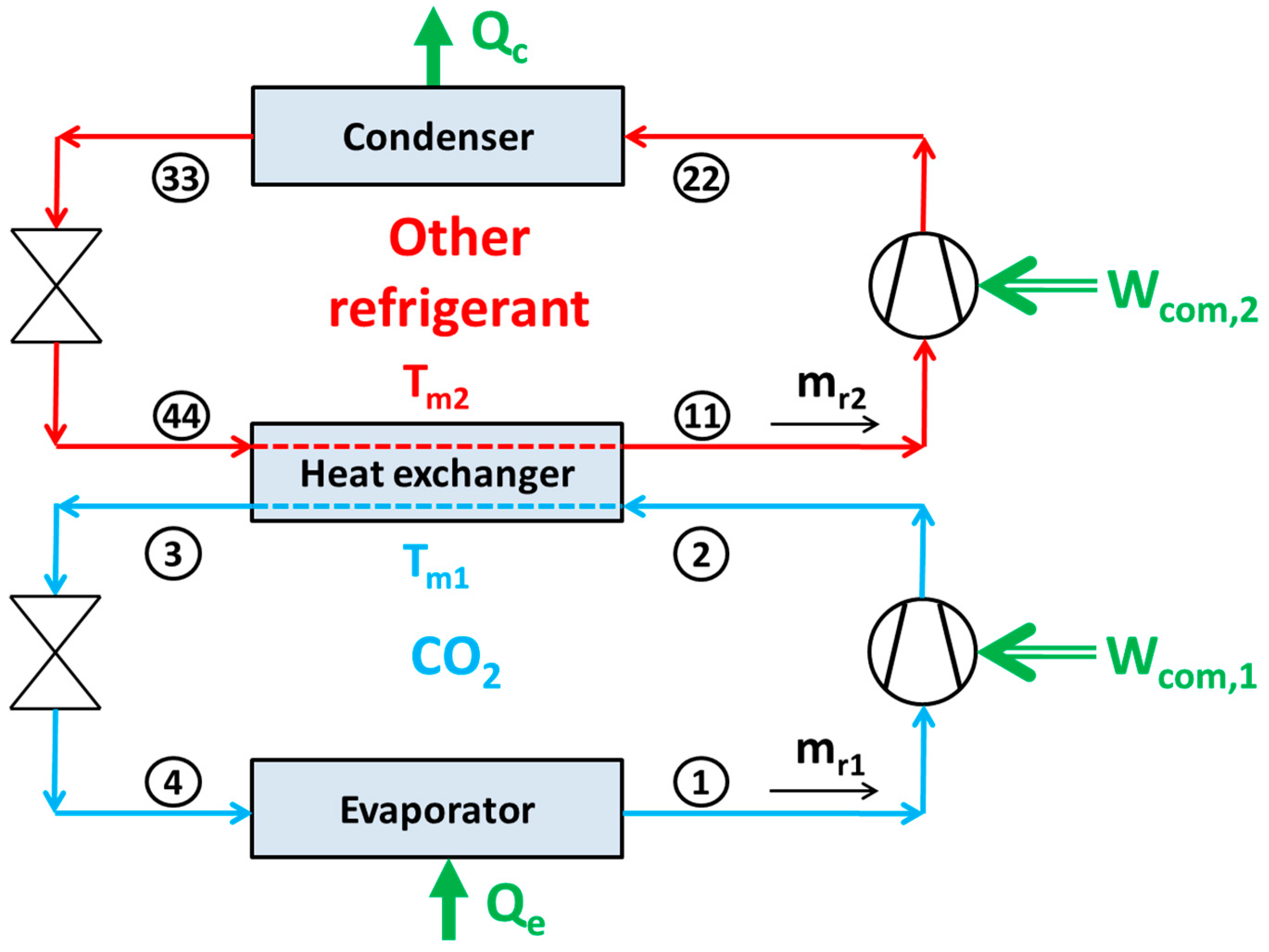
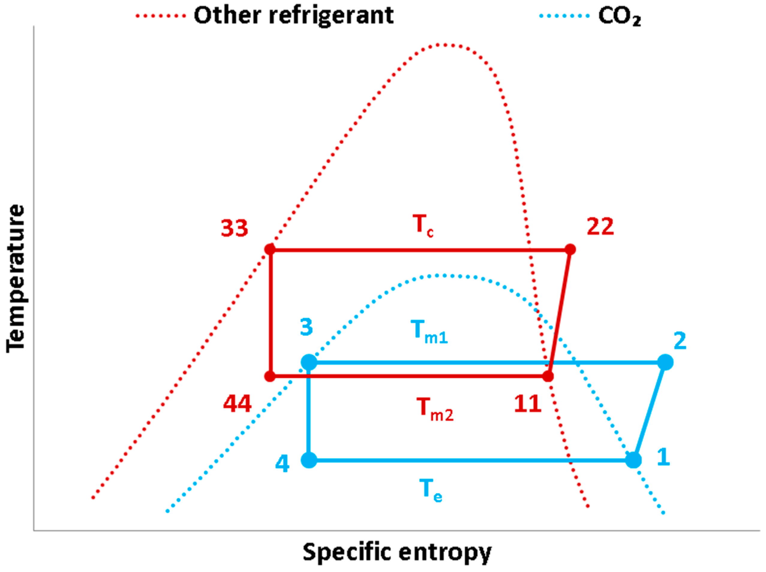
2.1. The Examined System

The examined system in this work is a cascade configuration which has the CO2 refrigerant in the low-temperature circuit and another refrigerant in the high-temperature circuit. Figure 1 gives a simple diagram of the examined configuration. The other examined refrigerants are listed in Table 1 with their details about GWP and ASHRAE safety group. Natural refrigerants (R290, R600a, R600, R1270, NH3), promising refrigerant with low GWP (R1234yf, R1234ze(E), R152a), refrigerants with medium GWP (R32, R448A, R513a. R450A) and high GWP refrigerants (R134a, R407C, R227ea, R404a, R507A). Moreover, the CO2/CO2 cascade system is examined as a reference one. It is important to state that the examined configuration is a subcritical cycle and only for high ambient temperatures the CO2/CO2 system operates in transcritical mode. At this point, it has to be said that another idea was the utilization of a CO2 booster system as the reference one. However, the goal of this work is to evaluate all the working fluids under the same operating conditions and so the CO2/CO2 cascade system was preferred in this work. Figure 2 shows the typical p-h depiction of the thermodynamic processes.
Figure 1 shows that there two systems, one with low-temperature levels where the CO2 operates and one system with higher temperatures with another refrigerant. There is a cascade heat exchanger in order the heat from the low-temperature system to be given to the high-temperature system. The temperature difference in this heat exchanger is assumed to be 5 K. Also, in this work the state points 1, 3, 11 and 33 are assumed to be saturated points. Figure 2 makes these assumptions obvious by observing the location of the various points. It is also useful to state that the condenser temperature is assumed to be 5 K higher than the ambient temperature level.

2.2. Mathematical Formulation

This subsection includes the main mathematical equations which have been used in the present work. These equations regard the modeling of the system and environmental evaluation.

2.2.1. System Modeling

The refrigeration production (Qe) in the evaporator can be written as below:
Q e = m r 1 · ( h 1 h 2 )
The energy rejection to the ambient (Qc) which is performed with the condenser is calculated as below:
Q c = m r 2 · ( h 22 h 33 )
The work input in the low circuit compressor (Wcom,1) is calculated as below:
W c o m , 1 = m r 1 · ( h 2 h 1 )
The work input in the high circuit compressor (Wcom,2) is calculated as below:
W c o m , 2 = m r 2 · ( h 22 h 11 )
The compressor performance is modeled using the isentropic efficiency (ηis), which can be written as below for the two compressors:
η is , 1 = h 2 i s h 1 h 2 h 1
η is , 2 = h 22 i s h 11 h 22 h 11
The isentropic efficiency is calculated using the respective pressure ratio (r), as the following equation shows [45]:
η is = 0.9343 0.04478 · r
The processes in the throttling valves are assumed to be adiabatic and so the enthalpy is the same between the inlet and the outlet. More specifically:
h 3 = h 4
h 33 = h 44
The energy balance in the cascade heat exchanger can be written as below:
m r 1 · ( h 2 h 3 ) = m r 2 · ( h 11 h 44 )
The temperature of the CO2 in the heat exchanger is (Tm1), while of the other refrigerant (Tm2), with the following equation to be applied for a proper heat transfer:
T m 2 = T m 1 5
The parameter (Tm1) is an optimization parameter for every case and it is always higher than (Te) and lower than (Tc). About the (Tc), it is assumed to about 5 K higher than the ambient temperature:
T c = T a m + 5
In the cases of the CO2/CO2 system, when the Tam is over 25 °C, then the system is assumed to be transcritical in the upper stage. In this case, the gas cooler outlet temperature is assumed to be 5 K over the ambient temperature and of course over the critical temperature of the CO2. Moreover, in this case, the high pressure of the gas cooler is also an optimization parameter. Finally, the thermodynamic COP in this system can be defined as:
C O P = Q e W c o m , 1 + W c o m , 2

2.2.2. Environmental Evaluation of the System

Except for the energetic analysis, the environmental evaluation is crucial for the systems with CO2 in order to examine their environmental imprint. The use of the total equivalent warming impact (TEWI) is a usual and useful index for this process. Details about the calculation of this index can be found in many studies such as [46,47]. The (TEWI) shows the amount of the equivalent CO2 emissions in all the life cycle of the system by taking into account the direct (TEWI)dir and the indirect (TWEI)ind CO2 emissions. So, it can be written:
( T E W I ) = ( T E W I ) d i r + ( T E W I ) i n d
The direct (TEWI) is separated into two parts. The first one regards the leakage and the other the recycling percentage of the working fluid:
( T E W I ) d i r = G W P 1 · [ L 1 · N + M 1 · ( 1 a 1 ) ] + G W P 2 · [ L 2 · N + M 2 · ( 1 a 2 ) ]
The subscript “1” regards the low-temperature circuit and the subscript “2” the high-temperature circuit. The leakage (L) is assumed to be 15% of the total mass of the refrigerant (M) [3,37]:
L i = 0.15 · M i
The mass of the refrigerant is assumed to be 1 kg kWref−1 for the CO2 and 2 kg kWref−1 for the other refrigerants. In this work, the refrigeration capacity is assumed to be 50 kWref, so the CO2 is 50 kg and the other refrigerant 100 kg. The years of the analysis (N) are assumed to be 10 and the recycling factors (a1 and a2) to be 95% [3,37].
The indirect (TEWI) regards the CO2 emissions for the production of the consumed electrical energy. Assuming that the yearly electricity consumption is (Eel) and an indirect emission factor (β), it can be written:
( T E W I ) i n d = E e l · β · N
For Athens (Greece), the parameter (β) is assumed to be 0.72 kg CO2,eq kWh−1 [3,37]. The yearly electrical efficiency is calculated as below:
E e l = t = 0 t = 8760 P e l d t
The mean yearly COP is calculated as below:
C O P m = t = 0 t = 8760 Q e d t t = 0 t = 8760 P e l d t

2.3. Followed Methodology

The present work evaluates different cascade refrigeration systems with a developed model in Engineering Equation Solver (EES) [48] which is validated by literature data (see Section 2.4). The refrigeration production is 50 kW and the refrigeration temperature is examined parametrically for −35, −25, −15 and −5 °C. The condenser temperature is studied at various temperature levels from 10 °C to 45 °C in the parametric analysis, while in the yearly evaluation of Athens it is 5 K higher than the ambient temperature. In every study, the high-temperature level of the lower temperature circuit (Tm1) is the optimization variable, while for the CO2/CO2 system also the high transcritical pressure is optimized. The optimization is conducted using the conjugate directions method or “Powell’s method” which is supported by the simulation tool (EES) [48]. The relative convergence tolerance is chosen at 10−8 and the maximum number of iterations (function calls) at 5000. About the yearly performance, the ambient temperature of Athens (Greece) is used. These data are given in Figure 3 and they have been taken by the TRNSYS libraries [49]. These weather data have been taken from past measurements and they correspond to the typical meteorological year for Athens. It can be said that the most usual value is 14 °C with 486 h, while the mean yearly temperature is around 18.4 °C. About the CO2/CO2 system, the transcritical operation regards 19% of the year period.
In the end, it is useful to summarize the main assumptions of this work [13,14]:
  • The system is examined in steady-state conditions.
  • There is no pressure drop in the evaporator, condenser and heat exchanger.
  • The throttling valve is assumed to be adiabatic and so the enthalpy is conserved.
  • The outlet streams from the evaporator, condenser and cascade heat exchanger are assumed to be saturated state points.
  • The temperature difference of the streams in the cascade heat exchanger is 5 K.
  • The condenser temperature is 5 K higher than the ambient temperature and for the CO2/CO2 system, the gas cooler outlet temperature is 5 K higher than the ambient.
  • The cooling capacity is 50 kW in all the cases.
  • All the compressor isentropic efficiencies are calculated according to Equation (7).
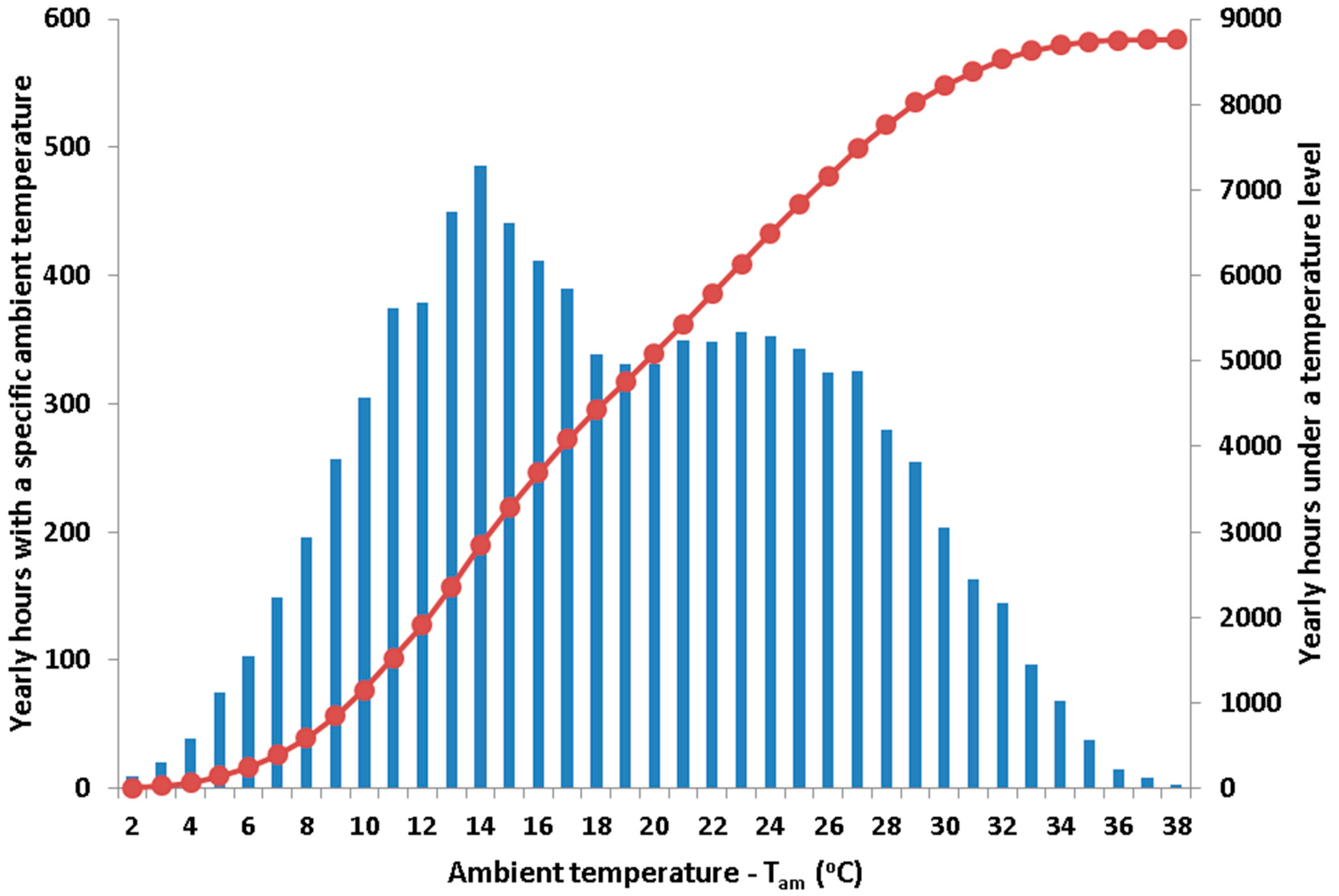
  • In the yearly analysis, the system is assumed to operate during all the year period.

2.4. Model Validation

The developed model is validated using literature data from reference [24]. The validation is conducted for the cascade system NH3/CO2 for different operating conditions. The proper modifications are performed in the program in order to simulate the respective system as in the Reference [24]. Table 2 includes comparative results. This table includes the examined cases (evaporator temperature and condenser temperature), as well as the optimum temperature (Tm1) and the respective COP. The found deviations are low and they are 0.37% for the (Tm1) and 1.32% for the COP. These values indicate that the developed model can be assumed as a valid one. However, it has to be stated that the validation is presented only for one working fluids couple among the examined.

3. Results and Discussion

The results of this work are mainly presented in terms of COP and in terms of TEWI. The examined systems are compared to the CO2/CO2 which can be assumed as the reference system. The emphasis is given in the natural refrigerants and generally in the refrigerants with low GWP. The refrigerants with high GWP are examined in order to present a complete comparative study.

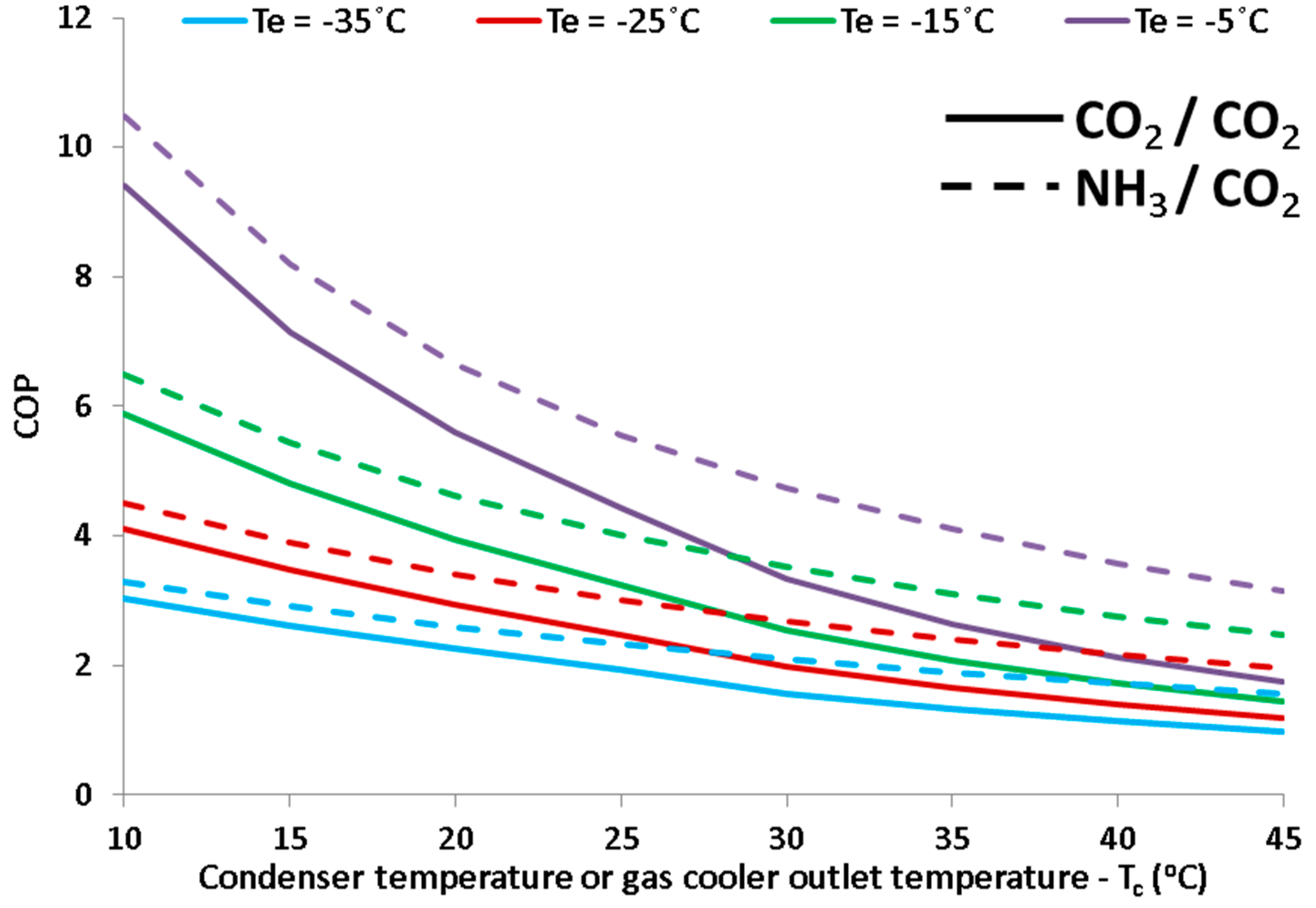
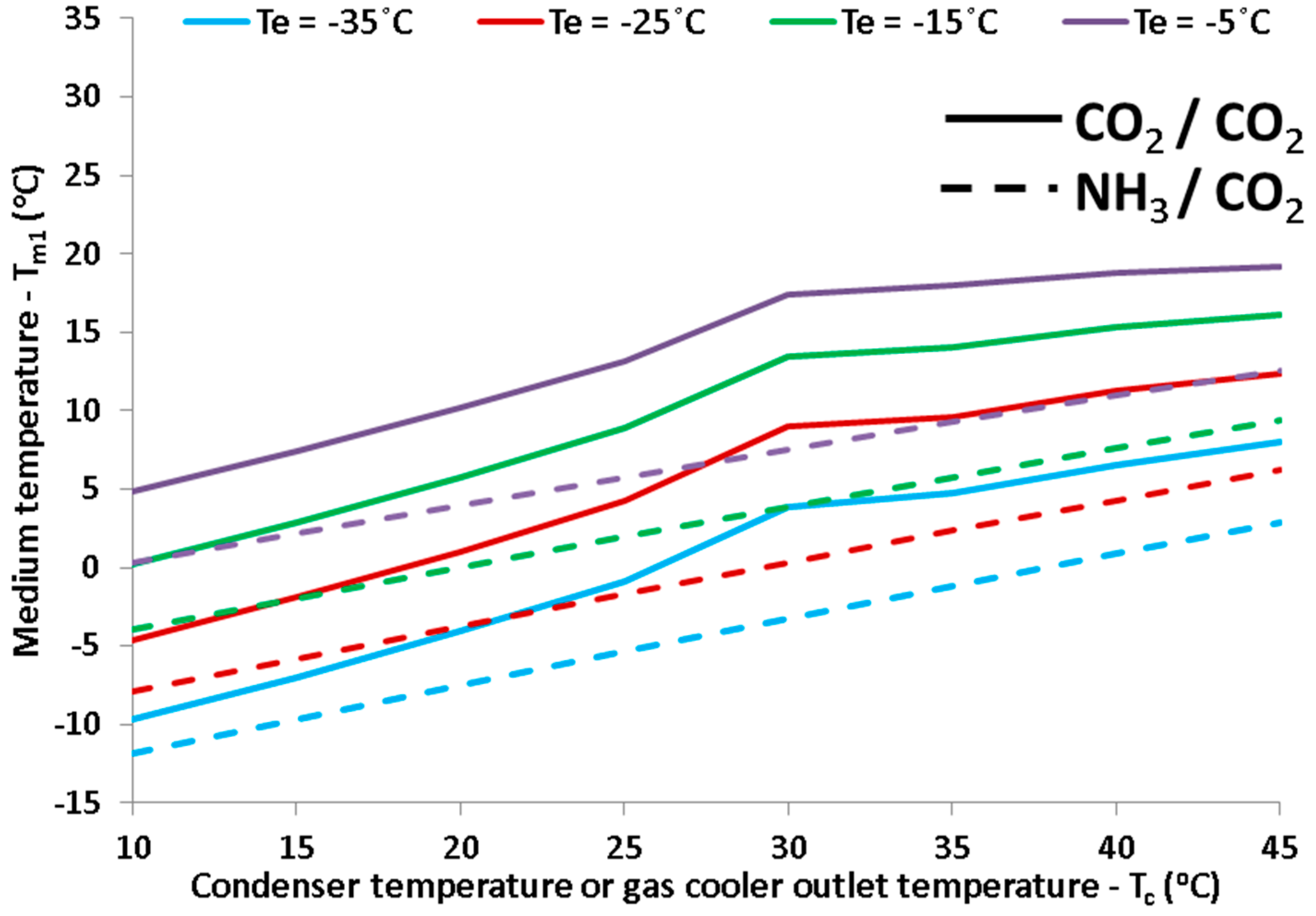
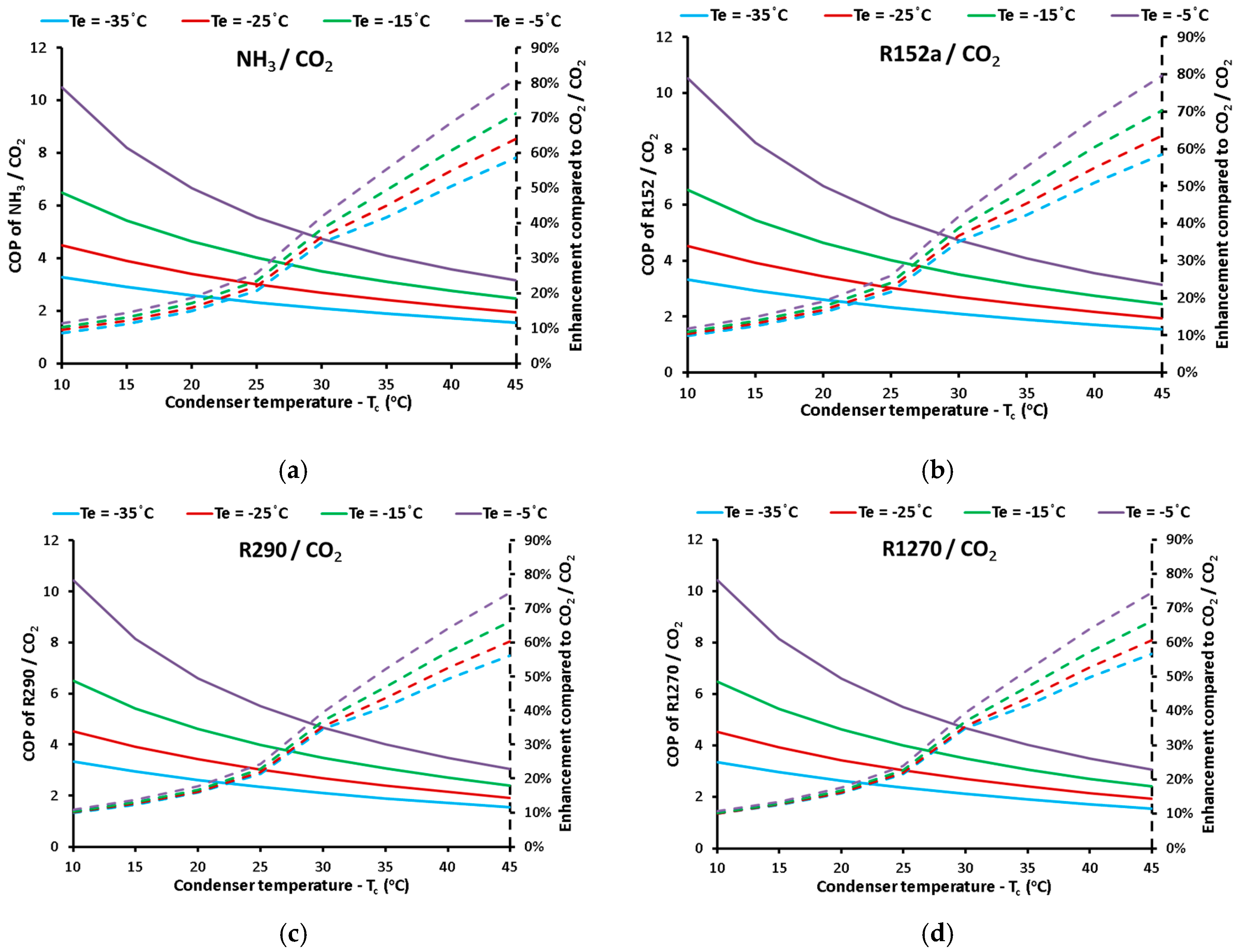
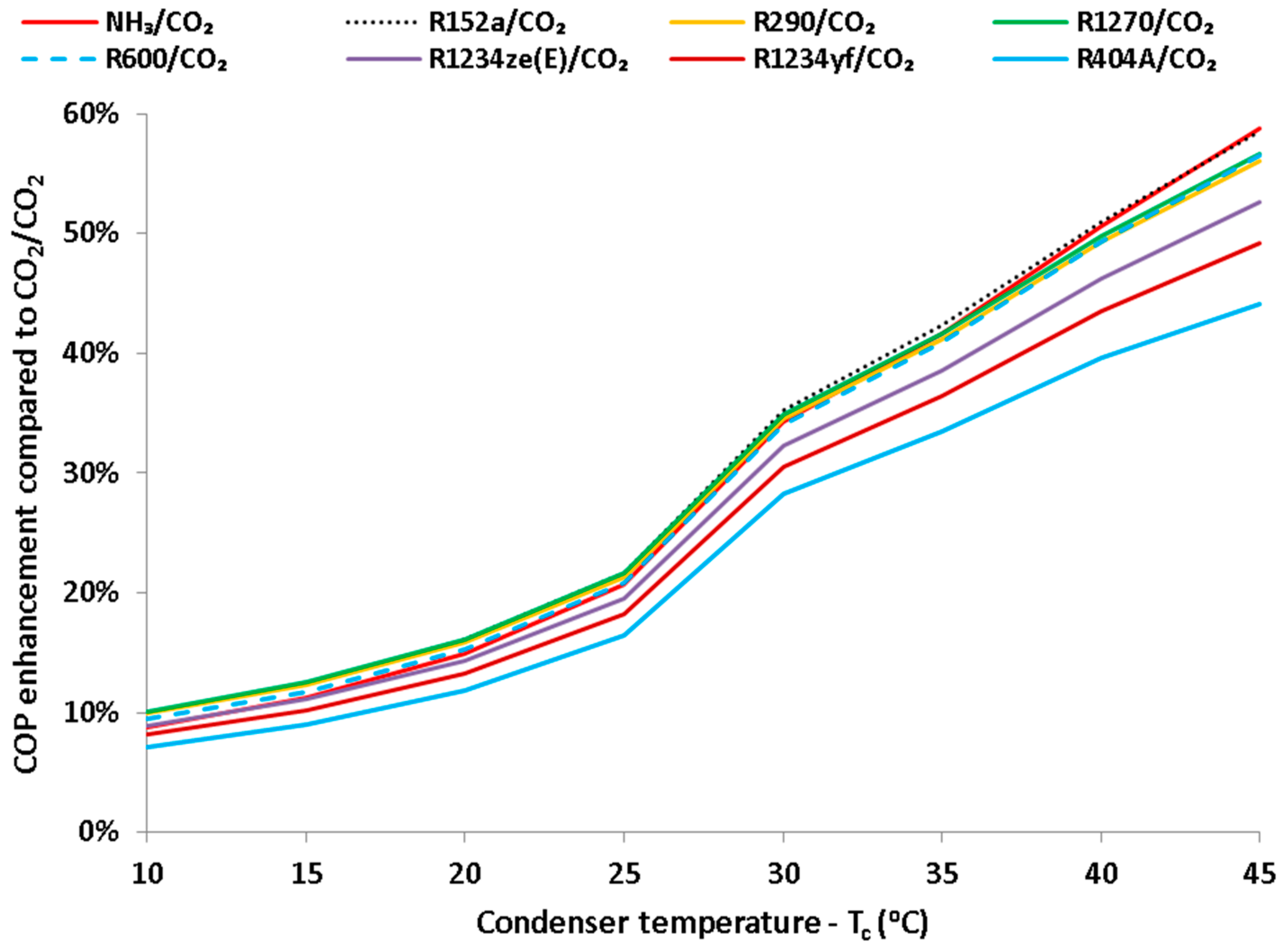
3.1. Energetic Analysis of Different Operating Scenarios

Figure 4 illustrates the COP of the systems CO2/CO2 (reference system for the comparison) and of the conventional system NH3/CO2 (it is usually examined in the literature). The results are presents for different condenser temperatures and evaporator temperatures. It is important to state again that for (Tc > 30 °C), the condenser temperature regards the gas cooler outlet temperature and the CO2/CO2 cycle is transcritical which operates at the respective optimum maximum pressure level in every case. It is obvious that the NH3/CO2 system is more efficient than the CO2/CO2 system for all the examined scenarios. The COP is decreased for higher condenser or gas cooler outlet temperatures and also it decreases for lower evaporate temperatures. These results are reasonable and they are in accordance with the Carnot efficiency [COPcar = Te/(TcTe)].
Figure 5 depicts the values of the optimum medium temperature level (Tm1) of the low-temperature CO2 cycle. The optimum values of the (Tm1) increase with the increase of the evaporator and the condenser temperature. So, it can be said that the optimum (Tm1) tries to follow temperatures levels of the (Te) and the (Tc). The interesting result is that the optimum (Tm1) is higher for the CO2/CO2 system compared to the NH3/CO2 system. It is remarkable to state that the slope of the curves about CO2/CO2 system changes after Tc = 30 °C because the cycle becomes transcritical for higher values of Tc. This result indicates that the transcritical cycle does not need so high values for the (Tm1).
The next step in this work is the comparison of the CO2/CO2 system with other cascade configurations. Figure 6 includes the comparison results for different combinations of (Te) and (Tc). The results are given for the systems NH3/CO2, R152a/CO2, R290/CO2 and R1270/CO2. The refrigerants R290 and R1270 are natural refrigerants, while R152a has a relatively low GWP. So, these candidates are promising choices for future cascade systems. Figure 6a,d indicate that the COP values are similar among the examined refrigerants.
The enhancement values compared to the CO2/CO2 system are higher for greater (Tc) and greater (Te). The COP enhancement curves have a different slope for (Tc > 30 °C) because of the transcritical operation of the CO2/CO2 system. Also, in low condenser temperatures, the COP enhancements are similar for all the evaporating temperatures, while for higher condenser temperatures the curves are not so close to each other. In low condenser temperatures, the COP enhancements are around 10%, while they can reach up to 80% in high condenser temperature levels. So, it can be said that the use of a refrigerant different from CO2 in the high-temperature circuit can be beneficial, especially in warmer climates. This is something in accordance with the general opinion about the utilization of cascade systems in warm climates such as in Mediterranean countries (for example Greece, Spain, Italy) [19].
Figure 7 shows the enhancement with 8 different refrigerants for the case of (Te = −35 °C). This evaporating temperature is typical, especially in refrigeration systems in supermarkets. This figure indicates that similar enhancements can be found with the examined refrigerants. The most promising choices seem to be R152a, NH3, R1270, R290 and R600a. R404a is the less efficient case, with R1234yf(E) and R1234ze to be a bit more efficient. These results are very encouraging because the most efficient refrigerants are environmentally friendly and so choices such as R404a are eliminated due to performance and environmental reasons.
For the temperature level of (Te = −35 °C), the enhancements reach up to 60% for (Tc = 45 °C) which indicate operation at the warmest summer days. On the other hand, the operation during the coldest days (Tc = 15 °C) the enhancements are up to 10%. In low condenser temperatures, the best refrigerant is R1270, while in high condenser temperatures the R152a is the best option. However, the differences between the R152a, NH3, R1270, R290 and R600a are very small. So, the selection of the working fluid cannot be determined only by this criterion, the COP value.

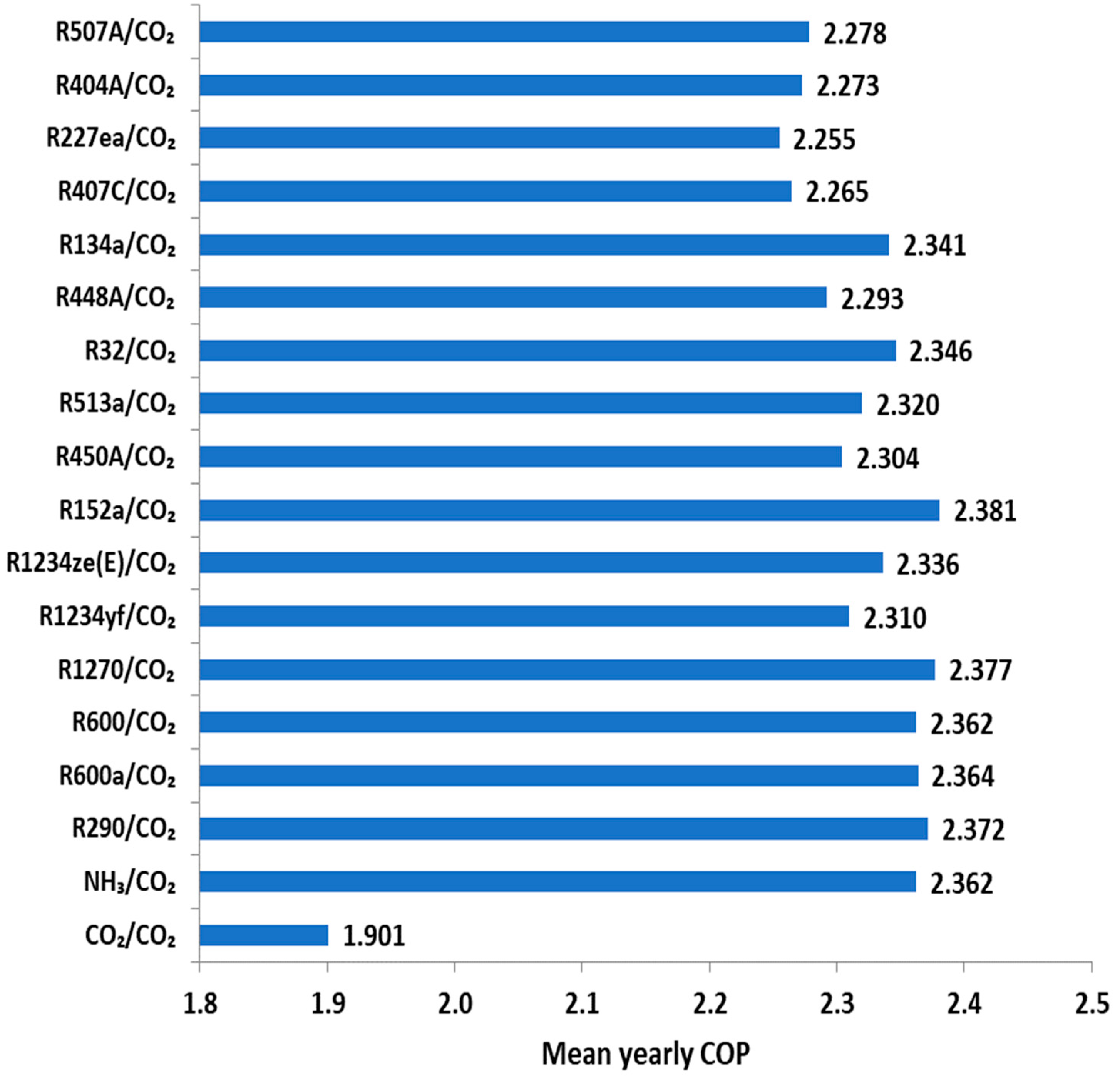
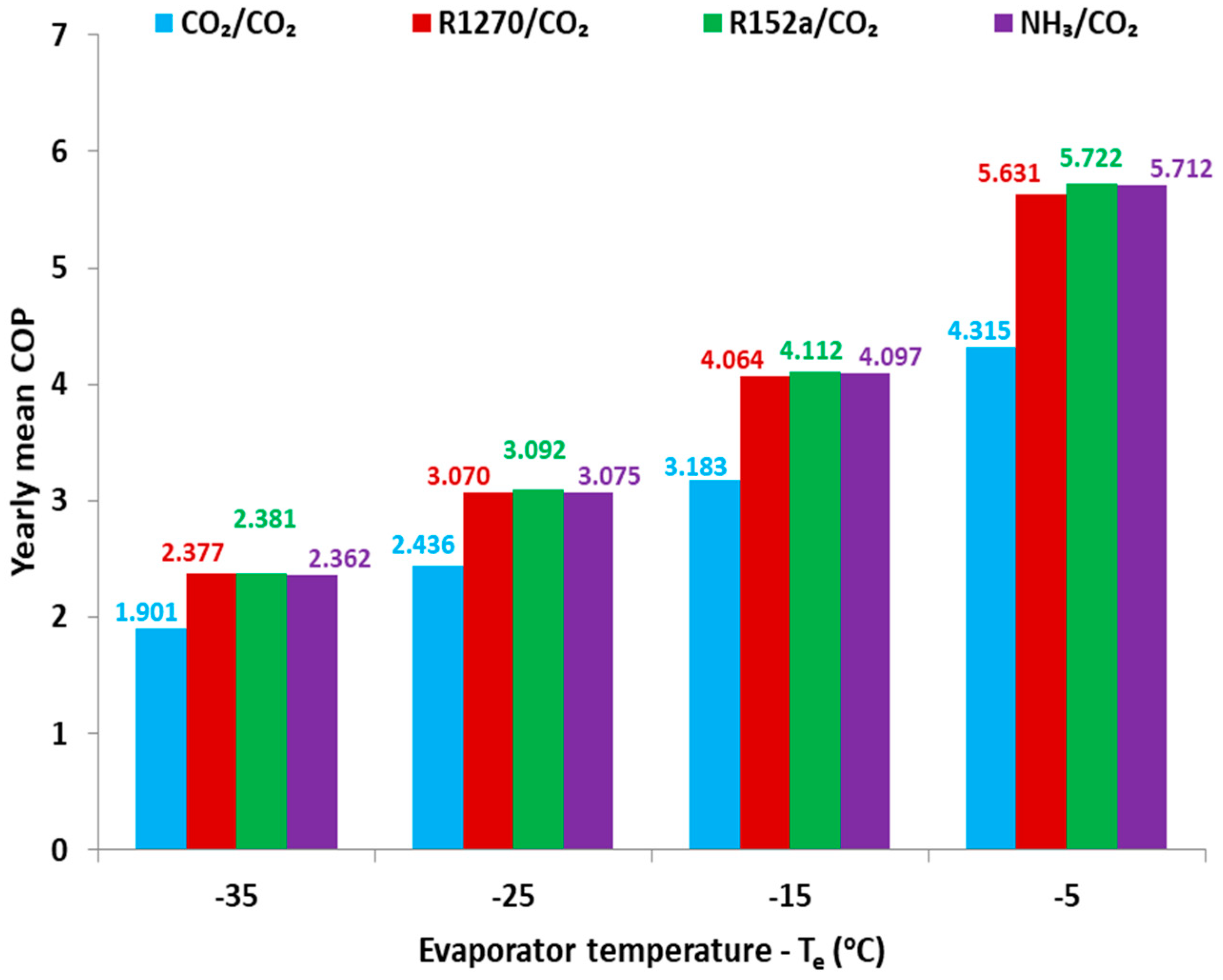
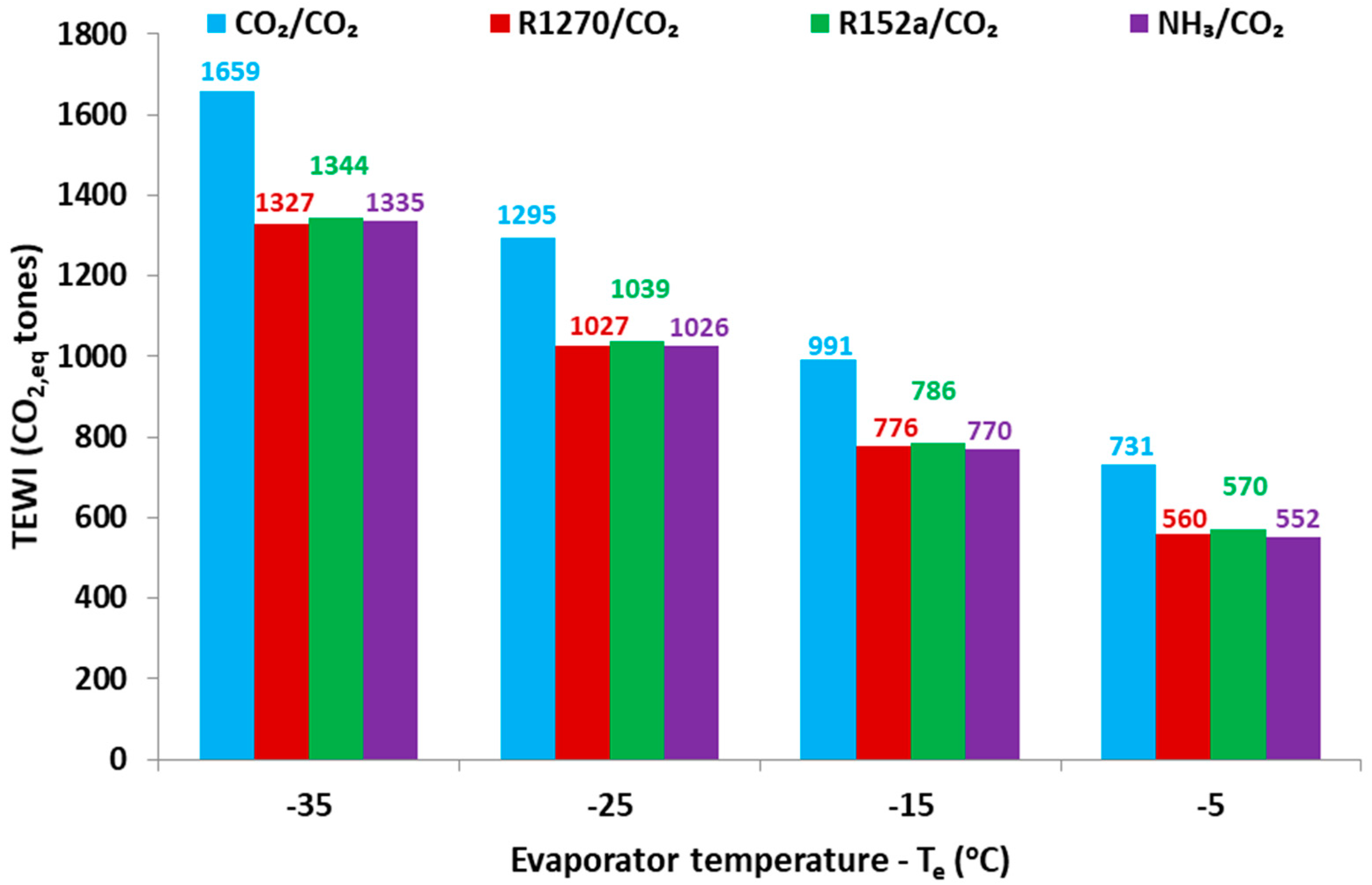
3.2. Yearly Energetic and Environmental Analysis

The yearly analysis of the system is performed using the weather data for Athens (Greece) which is a warm location. The distribution of the ambient temperature level is given in Figure 3 with a step of 1 K. The model is applied for all the temperatures and the mean yearly COP is calculated according to equation 19. The results for the typical evaporator temperature level of −35 °C are given in Figure 8. It is obvious that the CO2/CO2 system has the lowest efficiency among the examined systems with a value of 1.901. The most efficient is the R152a/CO2 system with 2.381, while R1270/CO2 is the second one with 2.377. Also, highly efficient systems are R290/CO2 with 2.372, R600a/CO2 with 2.364, as well as R600/CO2 and NH3/CO2 with 2.362.
The less efficient choices are R407C, R227ea, R404a, R507A and R448A. Generally, the refrigerants with the greater GWP present decreased efficiently. This is an important result which makes these harmful refrigerants to be not efficient and so they have no chances for application in the future refrigeration cascade configurations.
Figure 9 gives a detailed comparison for four evaporating temperatures by presenting results about CO2/CO2, R1270/CO2, R152a/CO2 and NH3/CO2. It is obvious that in all the evaporating temperatures, the mean yearly COP is lower for the configurations with CO2 in the high-temperature circuit. The three cases (R1270, R152a and NH3) have similar mean COP with R152a to present a roughly increase which is not so important. However, the high efficiency of R152a in combination with the low GWP of 124, are two factors which indicate it as a possible choice for refrigeration systems. Moreover, it is no toxic and less flammable than other natural refrigerants. So, the investigation and the application of R152a have a great interest. Lastly, it can be said that Table 3 includes all the data about the mean yearly COP of all the cases.
The next step is the environmental evaluation of the different refrigerants using the TEWI. This criterion needs the yearly electricity consumption and it regards a system lifetime of 10 years for this work. The results for all the systems are included in Table 4, while Figure 10 and Figure 11 give important results. More specifically, Figure 10 shows the total TEWI for all the refrigerants with (Te = −35 °C). Moreover, Figure 10 depicts the separation of the TEWI into the direct and indirect part. The most harmful fluids, which have the highest TEWI are the R507A, R404a, R227ea, R407c, R134a and R448A. The next category includes R32, R513A, R450A, while the lowest GWPI is found for the natural refrigerants, the R152a and the R1234yf, R1234ze(E). The system with CO2/CO2 is not the most environmentally friendly choice because of the huge indirect CO2 emissions. The low COP of this system makes the indirect TEWI be huge, the fact that makes this system to be among the most harmful scenarios. This is an extremely important result which makes the use of another refrigerant in the high-temperature circuit, except the CO2, to be an environmental need.
Discussing some typical values, the TEWI for CO2 is 1659.2, while the minimum value is 1326.8 for R1270 in the high-temperature circuit. The second choice is R290 with 1330.3, while R600a has 1334.6. NH3, R600, R152a, R1234yf and R1234ze(E) present similar values and they are also acceptable choices. The highest TEWI is 2002.0 for R507C, while R404a has 1995.3. Other usual refrigerants are R134a and R32 which has TEWI equal to 15.68.9 and 1448.8 respectively.
Figure 11 exhibits the TEWI for different evaporator temperatures. The values of the TEWI are lower for higher evaporator temperature because of the increase in the COP. The direct emissions are the same for all the evaporator temperatures while the indirect TEWI has a decreasing rate with the evaporator temperature increase. For (Te = −35 °C), the best case is R1270, while for higher evaporator temperatures the system with NH3 is the most environmental choice. However, the toxicity of NH3 creates a limitation for its application and important safety measures have to be taken.
So, by taking into consideration all the found results about mean yearly COP and TEWI, the most promising refrigerants are NH3, R1270 and R152a, while R600a, R600 and R290 are also interesting choices. The R152a and the R1270 are the best cases energetically, while NH3 and R1270 are the best cases environmentally. The NH3 faces toxicity limitations, while R290, R600a, R600 and R1270 are flammable refrigerants (A3 ASHRAE safety group). The R152a has lower flammability (A2 ASHRAE safety group) but it is a GWP of 124. This value is lower than the value of 150 which is acceptable according to the recent regulations [4]. However, in the future, this value maybe would be not acceptable. So, it can be said that there is no overall optimum choice and extra parameters such as the cost, the availability of the working fluids and the legislation of every period (and of every location) have to be taken into consideration for the final selection. This conclusion about the lack of a global optimum case about refrigerants has been also discussed in a recent review paper of Ciconkov [50].

4. Conclusions

The objective of this work is the investigation of different cascade configurations with CO2 in the low-temperature circuit and other refrigerants in the high-temperature circuit. The analysis is conducted with a developed model in EES, which is validated with literature data. The most important conclusions of this study are summarized below:
  • The COP of all the examined cascade systems is found to be higher than the reference scenario of the CO2/CO2 cascade configuration. The enhancements with the other systems are found from 10% up to 80% and they are higher for higher heat rejection temperatures.
  • The most efficient working fluids energetically, in the high-temperature circuit, are R152a, NH3, R1270, R600, R600a and R290. The less efficient systems, except CO2, are the refrigerants with high GWP such as R507A and R404a.
  • The maximum mean yearly COP is found for R152a/CO2 in all the evaporator temperatures and it is 2.381 for (Te = −35 °C), while the respective of CO2/CO2 is 1.901.
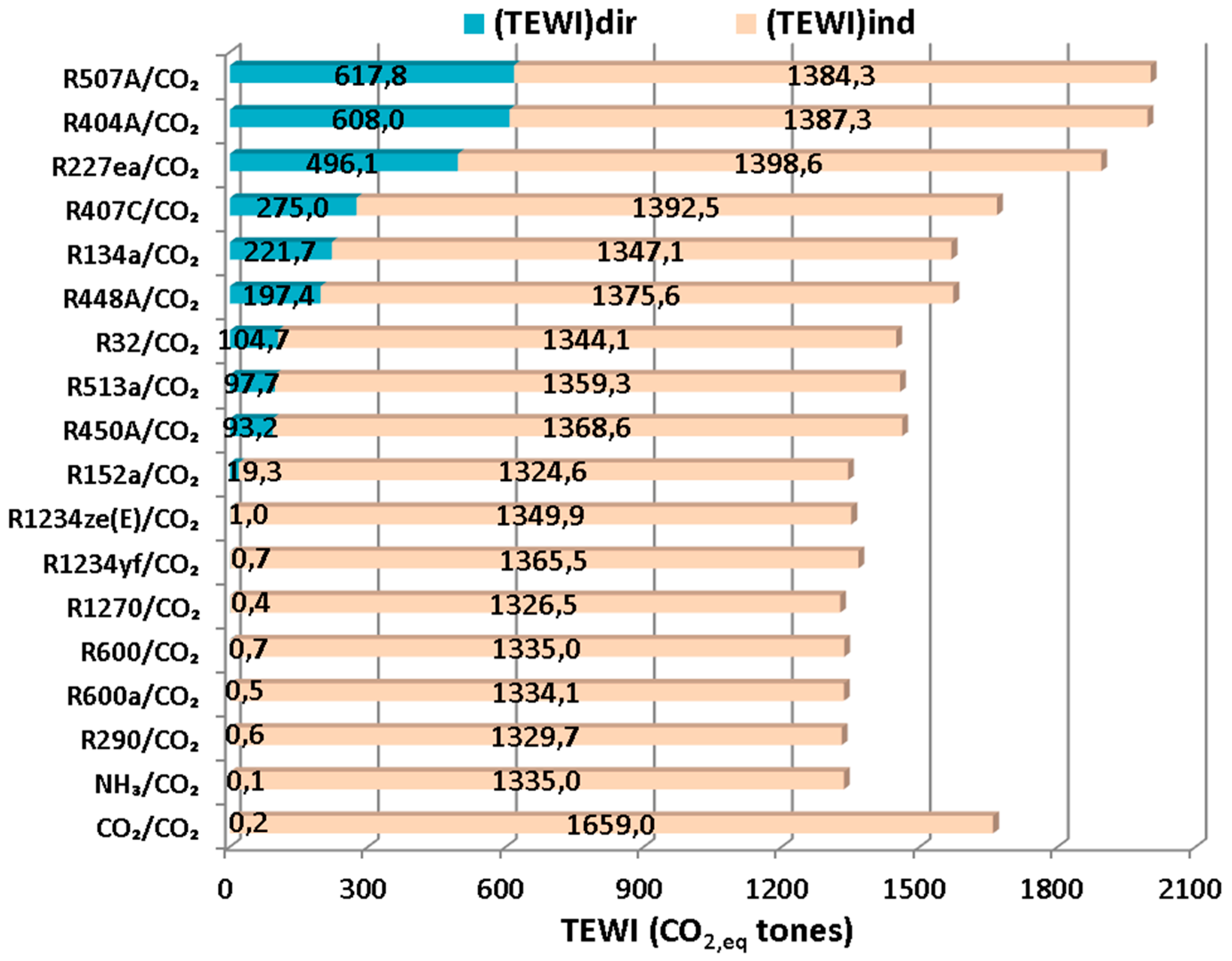
  • The environmental index TEWI shows that the CO2/CO2 is not a so good choice with the value of 1659.2 for (Te = −35 °C), while the R1270 has 1326.9. The natural refrigerants, the R152a, R1234yf and R1234ze(E) have also relatively low TEWI. The reason for the high value in the CO2/CO2 system is the high indirect TEWI.
  • It can be said that there is an overall optimum case because the most efficient choices have flammability and toxicity issues. R152a seems to be a promising choice but has a GWP of 124. So, for the final selection of the high-temperature circuit refrigerant, extra parameters such as the refrigerant cost and the legislation have to be taken into consideration in every case.

Author Contributions

All the authors have the same contribution in this paper.

Funding

This research is funded by “Bodossaki Foundation”.

Acknowledgments

Evangelos Bellos would like to thank “Bodossaki Foundation” for its financial support.

Conflicts of Interest

The authors declare no conflict of interest.

Nomenclature

COPCoefficient of performance, -
COPmMean yearly coefficient of performance, -
EelYearly electrical energy, kWh
hSpecific enthalpy, kJ kg−1 K−1
LYearly leakage, kg
mMass flow rate, kg s−1
MRefrigerant mass, kg
ΝLifetime of the system, years
QHeat rate, kW
rPressure ratio, -
TTemperature, °C
tTime, hours
TEWITotal equivalent warming impact, kg CO2,eq
WWork consumption in the compressor, kW
Greek Symbols
αRecycling factor, -
βIndirect emission factor, kg CO2,eq kWh−1.
ηisIsentropic efficiency of the compressor, -
Subscripts and Superscripts
amAmbient
cCondenser
carCarnot
comCompressor
eEvaporator
isIsentropic
m1Medium in low circuit
m2Medium in high circuit
optOptimum
rRefrigerant
Abbreviations
EESEngineering Equation Solver
GWPGlobal Warming Potential (100 years)
HCHydrocarbon
HFOHydrofluoroolefin
HOHydroolefin

References

  1. Sanz-Kock, C.; Llopis, R.; Sánchez, D.; Cabello, R.; Torrella, E. Experimental evaluation of a R134a/CO2 cascade refrigeration plant. Appl. Therm. Eng. 2014, 73, 41–50. [Google Scholar] [CrossRef]
  2. Nebot-Andrés, L.; Llopis, R.; Sánchez, D.; Catalán-Gil, J.; Cabello, R. CO2 with Mechanical Subcooling vs. CO2 Cascade Cycles for Medium Temperature Commercial Refrigeration Applications Thermodynamic Analysis. Appl. Sci. 2017, 7, 955. [Google Scholar] [CrossRef]
  3. Gullo, P.; Elmegaard, B.; Cortella, G. Energy and environmental performance assessment of R744 booster supermarket refrigeration systems operating in warm climates. Int. J. Refrig. 2016, 64, 61–79. [Google Scholar] [CrossRef] [Green Version]
  4. European Commission. Regulation (EU) No 517/2014 of the European Parliament and of the Council of 16th April 2014 on Fluorinated Greenhouse Gases and Repealing Regulation (EC) No 842/2006; European Commission: Brussels, Belgium; Luxembourg, 2014. [Google Scholar]
  5. Bellos, E.; Tzivanidis, C. Investigation of the Environmentally-Friendly Refrigerant R152a for Air Conditioning Purposes. Appl. Sci. 2019, 9, 119. [Google Scholar] [CrossRef]
  6. Chen, Y.; Gu, J. The optimum high pressure for CO2 transcritical refrigeration systems with internal heat exchangers. Int. J. Refrig. 2005, 28, 1238–1249. [Google Scholar] [CrossRef]
  7. Torrella, E.; Sánchez, D.; Llopis, R.; Cabello, R. Energetic evaluation of an internal heat exchanger in a CO2 transcritical refrigeration plant using experimental data. Int. J. Refrig. 2011, 34, 40–49. [Google Scholar] [CrossRef]
  8. Cavallini, A.; Cecchinato, L.; Corradi, M.; Fornasieri, E.; Zilio, C. Two-stage transcritical carbon dioxide cycle optimisation: A theoretical and experimental analysis. Int. J. Refrig. 2005, 28, 1274–1283. [Google Scholar] [CrossRef]
  9. Sarkar, J.; Agrawal, N. Performance optimization of transcritical CO2 cycle with parallel compression economization. Int. J. Therm. Sci. 2010, 49, 838–843. [Google Scholar] [CrossRef]
  10. Gullo, P.; Elmegaard, B.; Cortella, G. Advanced exergy analysis of a R744 booster refrigeration system with parallel compression. Energy 2016, 107, 562–571. [Google Scholar] [CrossRef] [Green Version]
  11. Chesi, A.; Esposito, F.; Ferrara, G.; Ferrari, L. Experimental analysis of R744 parallel compression cycle. Appl. Energy 2014, 135, 274–285. [Google Scholar] [CrossRef]
  12. Koeln, J.P.; Alleyne, A.G. Optimal subcooling in vapor compression systems via extremum seeking control: Theory and experiments. Int. J. Refrig. 2014, 43, 14–25. [Google Scholar] [CrossRef]
  13. Llopis, R.; Nebot-Andrés, L.; Cabello, R.; Sánchez, D.; Catalán-Gil, J. Experimental evaluation of a CO2 transcritical refrigeration plant with dedicated mechanical subcooling. Int. J. Refrig. 2016, 69, 361–368. [Google Scholar] [CrossRef]
  14. Dai, B.; Liu, S.; Li, H.; Sun, Z.; Song, M.; Yang, Q.; Ma, Y. Energetic performance of transcritical CO2 refrigeration cycles with mechanical subcooling using zeotropic mixture as refrigerant. Energy 2018, 150, 205–221. [Google Scholar] [CrossRef]
  15. Sánchez, D.; Catalán-Gil, J.; Llopis, R.; Nebot-Andrés, L.; Cabello, R.; Torrella, E. Improvements in a CO2 transcritical plant working with two different subcooling systems. In Proceedings of the 12th IIR Gustav Lorentzen Conference on Natural Refrigerants (GL2016), Edinburgh, UK, 21–24 August 2016. [Google Scholar]
  16. Nakagawa, M.; Marasigan, A.R.; Matsukawa, T.; Kurashina, A. Experimental investigation on the effect of mixing length on the performance of two-phase ejector for CO2 refrigeration cycle with and without heat exchanger. Int. J. Refrig. 2011, 34, 1604–1613. [Google Scholar] [CrossRef]
  17. Chen, G.; Volovyk, O.; Zhu, D.; Ierin, V.; Shestopalov, K. Theoretical analysis and optimization of a hybrid CO2 transcritical mechanical compression—Ejector cooling cycle. Int. J. Refrig. 2017, 74, 86–94. [Google Scholar] [CrossRef]
  18. Yang, J.L.; Ma, Y.T.; Liu, S.C. Performance investigation of transcritical carbon dioxide two-stage compression cycle with expander. Energy 2007, 32, 237–245. [Google Scholar] [CrossRef]
  19. Catalán-Gil, J.; Sánchez, D.; Llopis, R.; Nebot-Andrés, L.; Cabello, R. Energy Evaluation of Multiple Stage Commercial Refrigeration Architectures Adapted to F-Gas Regulation. Energies 2018, 11, 1915. [Google Scholar] [CrossRef]
  20. Available online: https://www.ghgprotocol.org/sites/default/files/ghgp/Global-Warming-Potential-Values%20%28Feb%2016%202016%29_1.pdf (accessed on 5 November 2018).
  21. Available online: https://en.wikipedia.org/wiki/List_of_refrigerants (accessed on 5 November 2018).
  22. Abas, N.; Kalair, A.R.; Khan, N.; Haider, A.; Saleem, Z.; Saleem, M.S. Natural and synthetic refrigerants, global warming: A review. Renew. Sustain. Energy Rev. 2018, 90, 557–569. [Google Scholar] [CrossRef]
  23. Bingming, W.; Huagen, W.; Jianfeng, L.; Ziwen, X. Experimental investigation on the performance of NH3/CO2 cascade refrigeration system with twin-screw compressor. Int. J. Refrig. 2009, 32, 1358–1365. [Google Scholar] [CrossRef]
  24. Lee, T.-S.; Liu, C.-H.; Chen, T.-W. Thermodynamic analysis of optimal condensing temperature of cascade-condenser in CO2/NH3 cascade refrigeration systems. Int. J. Refrig. 2006, 29, 1100–1108. [Google Scholar] [CrossRef]
  25. Rezayan, O.; Behbahaninia, A. Thermoeconomic optimization and exergy analysis of CO2/NH3 cascade refrigeration systems. Energy 2011, 36, 888–895. [Google Scholar] [CrossRef]
  26. Yilmaz, B.; Mancuhan, E.; Erdonmez, N. A Parametric Study on a Subcritical CO2/NH3 Cascade Refrigeration System for Low Temperature Applications. ASME J. Energy Resour. Technol. 2018, 140, 092004. [Google Scholar] [CrossRef]
  27. Gholamian, E.; Hanafizadeh, P.; Ahmadi, P. Advanced exergy analysis of a carbon dioxide ammonia cascade refrigeration system. Appl. Therm. Eng. 2018, 137, 689–699. [Google Scholar] [CrossRef]
  28. Dokandari, D.A.; Hagh, A.S.; Mahmoudi, S.M.S. Thermodynamic investigation and optimization of novel ejector-expansion CO2/NH3 cascade refrigeration cycles (novel CO2/NH3 cycle). Int. J. Refrig. 2014, 46, 26–36. [Google Scholar] [CrossRef]
  29. Bhattacharyya, S.; Bose, S.; Sarkar, J. Exergy maximization of cascade refrigeration cycles and its numerical verification for a transcritical CO2–C3H8 system. Int. J. Refrig. 2007, 30, 624–632. [Google Scholar] [CrossRef]
  30. Dubey, A.M.; Kumar, S.; Agrawal, G.D. Thermodynamic analysis of a transcritical CO2/propylene (R744–R1270) cascade system for cooling and heating applications. Energy Convers. Manag. 2014, 86, 774–783. [Google Scholar] [CrossRef]
  31. Megdouli, K.; Ejemni, N.; Nahdi, E.; Mhimid, A.; Kairouani, L. Thermodynamic analysis of a novel ejector expansion transcritical CO2/N2O cascade refrigeration (NEETCR) system for cooling applications at low temperatures. Energy 2017, 128, 586–600. [Google Scholar] [CrossRef]
  32. Bhattacharyya, S.; Garai, A.; Sarkar, J. Thermodynamic analysis and optimization of a novel N2O–CO2 cascade system for refrigeration and heating. Int. J. Refrig. 2009, 32, 1077–1084. [Google Scholar] [CrossRef]
  33. Sanchez, D.; Llopis, R.; Cabello, R.; Catalán-Gil, J.; Nebot-Andrés, L. Conversion of a direct to an indirect commercial (HFC134a/CO2) cascade refrigeration system: Energy impact analysis. Int. J. Refrig. 2017, 73, 183–199. [Google Scholar] [CrossRef]
  34. Cabello, R.; Sánchez, D.; Llopis, R.; Catalán, J.; Nebot-Andrés, L.; Torrella, E. Energy evaluation of R152a as drop in replacement for R134a in cascade refrigeration plants. Appl. Therm. Eng. 2017, 110, 972–984. [Google Scholar] [CrossRef] [Green Version]
  35. Da Silva, A.; Filho, E.P.B.; Antunes, A.H.P. Comparison of a R744 cascade refrigeration system with R404A and R22 conventional systems for supermarkets. Appl. Therm. Eng. 2012, 41, 30–35. [Google Scholar] [CrossRef]
  36. Byrne, P.; Miriel, J.; Lenat, Y. Design and simulation of a heat pump for simultaneous heating and cooling using HFC or CO2 as a working fluid. Int. J. Refrig. 2009, 32, 1711–1723. [Google Scholar] [CrossRef]
  37. Tsamos, K.M.; Ge, Y.T.; Santosa, I.; Tassou, S.A.; Bianchi, G.; Mylona, Z. Energy analysis of alternative CO2 refrigeration system configurations for retail food applications in moderate and warm climates. Energy Convers. Manag. 2017, 150, 822–829. [Google Scholar] [CrossRef]
  38. Nasruddin; Sholahudin, S.; Giannetti, N.; Arnas. Optimization of a cascade refrigeration system using refrigerant C3H8 in high temperature circuits (HTC) and a mixture of C2H6/CO2 in low temperature circuits (LTC). Appl. Therm. Eng. 2016, 104, 96–103. [Google Scholar] [CrossRef]
  39. Beshr, M.; Aute, V.; Sharma, V.; Abdelaziz, O.; Fricke, B.; Radermacher, R. A comparative study on the environmental impact of supermarket refrigeration systems using low GWP refrigerants. Int. J. Refrig. 2015, 56, 154–164. [Google Scholar] [CrossRef] [Green Version]
  40. Di Nicola, G.; Polonara, F.; Stryjek, R.; Arteconi, A. Performance of cascade cycles working with blends of CO2 + natural refrigerants. Int. J. Refrig. 2011, 34, 1436–1445. [Google Scholar] [CrossRef]
  41. Colorado, D.; Hernández, J.A.; Rivera, W. Comparative study of a cascade cycle for simultaneous refrigeration and heating operating with ammonia, R134a, butane, propane, and CO2 as working fluids. Int. J. Sustain. Energy 2012, 31, 365–381. [Google Scholar] [CrossRef]
  42. Cecchinato, L.; Corradi, M.; Minetto, S. Energy performance of supermarket refrigeration and air conditioning integrated systems working with natural refrigerants. Appl. Therm. Eng. 2012, 48, 378–391. [Google Scholar] [CrossRef]
  43. Getu, H.M.; Bansal, P.K. Thermodynamic analysis of an R744–R717 cascade refrigeration system. Int. J. Refrig. 2008, 31, 45–54. [Google Scholar] [CrossRef]
  44. Purohit, N.; Sharma, V.; Sawalha, S.; Fricke, B.; Llopis, R.; Dasgupta, M.S. Integrated supermarket refrigeration for very high ambient temperature. Energy 2018, 165A, 572–590. [Google Scholar] [CrossRef]
  45. Brown, J.S.; Yana-Motta, S.F.; Domanski, P.A. Comparitive analysis of an automotive air conditioning systems operating with CO2 and R134a. Int. J. Refrig. 2002, 25, 19–32. [Google Scholar] [CrossRef]
  46. AIRAH. Methods of Calculating Total Equivalent Warming Impact (TEWI) 2012. Available online: http://www.airah.org.au (accessed on 24 October 2018).
  47. Gullo, P.; Tsamos, K.M.; Hafner, A.; Banasiak, K.; Ge, Y.T.; Tassou, S.A. Crossing CO2 equator with the aid of multi-ejector concept: A comprehensive energy and environmental comparative study. Energy 2018, 164, 236–263. [Google Scholar] [CrossRef]
  48. F-Chart Software, Engineering Equation Solver (EES). 2015. Available online: http://www.fchart.com/ees (accessed on 5 November 2018).
  49. Available online: http://www.trnsys.com/ (accessed on 5 November 2018).
  50. Ciconkov, R. Refrigerants: There is still no vision for sustainable solutions. Int. J. Refrig. 2018, 86, 441–448. [Google Scholar] [CrossRef]
Figure 1. The examined cascade configuration.
Applsci 09 00790 g001
Figure 2. Typical temperature-specific entropy figure for the examined processes.
Applsci 09 00790 g002
Figure 3. Data about the ambient temperature in Athens (Greece).
Applsci 09 00790 g003
Figure 4. Coefficient of performance (COP) at different operating conditions for CO2/CO2 and CO2/NH3 systems.
Applsci 09 00790 g004
Figure 5. Optimum medium temperature (Tm1) at different operating conditions for CO2/CO2 and CO2/NH3 systems.
Applsci 09 00790 g005
Figure 6. COP and the enhancements compared to CO2/CO2 for the systems (a) NH3/CO2; (b) R152a/CO2; (c) R290/CO2; (d) R1270/CO2.
Applsci 09 00790 g006
Figure 7. COP enhancement compared to the CO2/CO2 system of various systems with Te = −35 °C.
Applsci 09 00790 g007
Figure 8. Mean yearly COP of the examined systems for Te = −35 °C.
Applsci 09 00790 g008
Figure 9. Mean yearly COP of four cases for different evaporator temperatures.
Applsci 09 00790 g009
Figure 10. TEWI of the examined systems for Te = −35 °C.
Applsci 09 00790 g010
Figure 11. TEWI of four cases for different evaporator temperatures.
Applsci 09 00790 g011
Table 1. Refrigerants and their characteristics [20,21,22].
Working FluidsClassificationGWP (100 Years)ASHRAE Safety GroupLimitations
R744 (CO2)Natural refrigerant1A1Low COP
R717 (NH3)Natural refrigerant0B2LHigh Toxicity
R290 (propane)HC (Natural refrigerant)3.3A3High flammability
R600a (iso-butane)HC (Natural refrigerant)3A3High flammability
R600 (butane)HC (Natural refrigerant)4A3High flammability
R1270 (propylene)HO (Natural refrigerant)1.8A3High flammability
R1234yfHFO4A2LLow flammability, Stability issues
R1234ze(E)HFO6A2LLow flammability, Stability issues
R152aHFC124A2Intermediate Flammability, Low GWP
R450AHFO601A1High GWP > 150
R513AHFO630A1High GWP > 150
R32HFC675A2LLow flammability, Medium GWP
R448AHFO1273A1High GWP
R134aHFC1430A1High GWP
R407CHFC1774A1High GWP
R227eaHFC3200A1High GWP
R404AHFC3922A1High GWP
R507AHFC3985A1High GWP
Table 2. Model validation with literature data [24].
CasesLiteratureThis StudyDeviation
Tc (°C)Te (°C)Tm1,opt (°C)COPTm1,opt (°C)COPTm1,opt (°C)COP
30−45−151.44−15.011.4270.07%0.90%
30−50−171.27−17.121.2500.71%1.57%
30−55−191.10−19.161.0890.84%1.00%
35−45−131.31−13.001.2980.00%0.92%
35−50−151.15−15.041.1380.27%1.04%
35−55−171.01−17.010.9910.06%1.88%
40−45−111.20−10.981.1820.18%1.50%
40−50−131.05−12.961.0370.31%1.24%
40−55−150.92−14.860.9030.93%1.85%
Table 3. Yearly values of the mean COP for the examined cases.
RefrigerantsYearly Mean COP
Te = −35 °CTe = −25 °CTe = −15 °CTe = −5 °C
CO2/CO21.9012.4363.1834.315
NH3/CO22.3623.0754.0975.712
R290/CO22.3723.0674.0645.636
R600a/CO22.3643.0724.0885.693
R600/CO22.3623.0754.0975.712
R1270/CO22.3773.0704.0645.631
R1234yf/CO22.3103.0013.9915.552
R1234ze(E)/CO22.3363.0404.0505.645
R152a/CO22.3813.0924.1125.722
R450A/CO22.3042.9963.9875.547
R513a/CO22.3203.0144.0085.576
R32/CO22.3463.0364.0235.578
R448A/CO22.2932.9733.9475.477
R134a/CO22.3413.0434.0495.637
R407C/CO22.2652.9373.8955.399
R227ea/CO22.2552.9443.9295.483
R404A/CO22.2732.9463.9095.421
R507A/CO22.2782.9533.9185.434
Table 4. Total equivalent warming impact for the examined cases.
RefrigerantsTEWI (CO2,eq Tones)
Te = −35 °CTe = −25 °CTe = −15 °CTe = −5 °C
CO2/CO21659.21294.6990.9731.1
NH3/CO21335.11025.7769.8552.1
R290/CO21330.31028.9776.7560.1
R600a/CO21334.61027.1772.0554.5
R600/CO21335.71026.3770.5552.8
R1270/CO21326.91027.4776.3560.4
R1234yf/CO21366.21051.6790.9568.7
R1234ze(E)/CO21351.01038.2779.6559.7
R152a/CO21343.91039.2786.3570.5
R450A/CO21461.81145.7884.3661.8
R513a/CO21457.01144.0884.5663.3
R32/CO21448.81143.6888.6670.0
R448A/CO21573.01258.0996.5773.2
R134a/CO21568.91258.01000.6781.2
R407C/CO21667.61348.91084.6859.1
R227ea/CO21894.61567.41298.71071.3
R404A/CO21995.31678.31414.81189.7
R507A/CO22002.01685.71422.71198.1

