Article

Thermomechanical Behavior of Textile Reinforced Cementitious Composites Subjected to Fire

1
Department Mechanics of Materials and Constructions, Vrije Universiteit Brussel (VUB), Pleinlaan 2, 1050 Brussels, Belgium
2
Department of Civil Engineering, Structural Materials Laboratory, University of Patras, 26504 Rio, Greece
3
Engineering Division, New York University Abu Dhabi, Saadiyat Island, PO Box 129188, UAE
*
Author to whom correspondence should be addressed.
Appl. Sci. 2019, 9(4), 747; https://doi.org/10.3390/app9040747
Submission received: 31 January 2019 / Revised: 15 February 2019 / Accepted: 18 February 2019 / Published: 21 February 2019

Abstract

:
The mechanical behavior of textile reinforced cementitious composites (TRC) has been a topic of wide investigation during the past 30 years. However, most of the investigation is focused on the behavior under ambient temperatures, while only a few studies about the behavior under high temperatures have been conducted thus far. This paper focused on the thermomechanical behavior of TRC after exposure to fire and the residual capacity was examined. The parameters that were considered were the fiber material, the thickness of the concrete cover, the moisture content and the temperature of exposure. The specimens were exposed to fire only from one side and the residual strength was measured by means of flexural capacity. The results showed that the critical factor that affects the residual strength was the coating of the textiles and the law of the coating mass loss with respect to temperature. The effect of the other parameters was not quantified. The degradation of the compressive strength of TRC was quantified with respect to temperature. It was also concluded that a highly asymmetrical design scheme might lead to premature failure.

1. Introduction

Innovation in construction has always been a matter of great interest. In the past decades, the materials that play a leading role towards this have been the textile reinforced cementitious composites, usually referred to as textile reinforced mortars (TRM), textile reinforced concrete (TRC) or fabric reinforced cementitious matrix composites (FRCM). TRC is a material that combines the good compressive behavior of cementitious matrices with the good tensile properties of a proper reinforcement. The innovation lies in the very high tensile capacity of the thin fibers, but especially in the slenderness offered by the lightweight textiles with respect to the traditional bulky steel reinforcement. Additionally, the most common fiber materials (glass, carbon, basalt, aramid) are much less prone to corrosion than steel, which leads to lower needs in concrete cover, thus, thinner and more lightweight elements. Additionally, TRC presents a significant advantage with respect to the fiber reinforced polymer (FRP) composite materials, through the increased resistance of the cementitious matrices to high temperatures with respect to the polymer matrices of FRPs. Finally, another important advantage of TRC with respect to FRPs is the higher compatibility of the cementitious matrices with most substrates; thus, TRC can be used as a retrofitting material in more applications in construction.
A major concern with respect to TRC lies in the fact that the low thickness of TRC elements might end up being a drawback for their fire resistance, since the textile reinforcement is more exposed to high temperatures. At the same time, the most common failure mechanism of concrete due to high temperatures (spalling of the cover) is of small importance in thick elements, while in TRC elements with thickness of a few millimeters it can be critical. Therefore, even though TRC has been widely investigated and already practically used in the past few years for many applications (load bearing or non-load bearing elements in new constructions, strengthening, repairing and seismic retrofitting of existing concrete or masonry buildings, sandwich façade panels, bridge components, curved shell elements, etc.), there is still no high certainty about the materials’ response in fire conditions.
The state-of-the-art in the literature includes several publications concerning the temperature effect on TRC. However, a significant amount on them is not focused on TRC alone, but on applications of TRC as a strengthening technique on existing concrete or masonry structures. Studies [1,2,3,4,5,6] investigate the effectiveness of a TRC layer as a means of strengthening concrete beams or slabs subjected to high temperatures. In studies [7,8] TRC has been used on existing concrete substrates; however, these studies have focused only on the effect of high temperatures on the bond between the two different materials. In publications [9,10,11], the structural capacity and the effectiveness of the bond between the TRC and masonry substrate has also been tested under exposure to high temperatures. Clearly, the results given by these publications cannot be used as data to work with in the design of TRC structures, since the high concrete (or masonry) mass of the existing building gives thermal inertia to the system which does not exist in slender TRC structures.
In studies [12,13,14,15,16,17,18,19,20,21,22,23,24,25,26,27,28], the structural capacity of TRC alone (not on a different substrate) under elevated or high temperature has been investigated. However, in [12,13,14,15,16,17,18,19,20,21], the maximum temperature that was tested was 650 °C, and only in publications [22,23,24,25,26,27,28], TRC was investigated under temperatures of 700 °C–1000 °C, which corresponds to the realistic temperatures developed in case of a cellulosic fire [29]. Moreover, out of the last group of publications, only in [26,28] tests have been performed on TRC specimens according to the standard fire curve proposed by EN1363 ([29]), while using glass or carbon fiber reinforcement, which are the most commonly used in structural applications.
In conclusion, publications that investigate TRC as a structural material under realistic fire conditions are scarce, and there is a large gap of knowledge on the behavior and design of this new material for the accidental load case of fire.

2. Materials and Methods

2.1. Matrix

The matrix that was used in this study is a commercially available cementitious mortar of ordinary Portland cement. It included quartz sand at a percentage of 25%–30% by weight as well as some additives, which were not disclosed by the manufacturer. The maximum grain size was 2.5 mm, and the mortar had a high flowability, which was necessary for casting properly through the textile reinforcement.
The compressive and flexural strength of the mortar were measured by conducting compression and three-point bending tests according to EN 12190 and EN 196-1, respectively. They were measured after 28 days of casting and with identical curing conditions as those of the TRC specimens that will be described below (cured at constant temperature of 20 °C and covered with constantly wet fabrics).
The compressive strength, measured by testing six specimens (cubes of 40 mm), was found equal to 61.45 MPa, with a variance of 4.16 MPa. The flexural strength, measured by testing five specimens (prisms of 40 × 40 × 160 mm), was found equal to 7.60 MPa with a variance of 0.93 MPa.

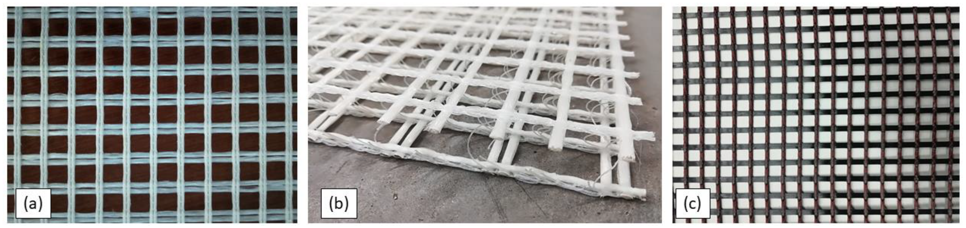
2.2. Textile Reinforcement
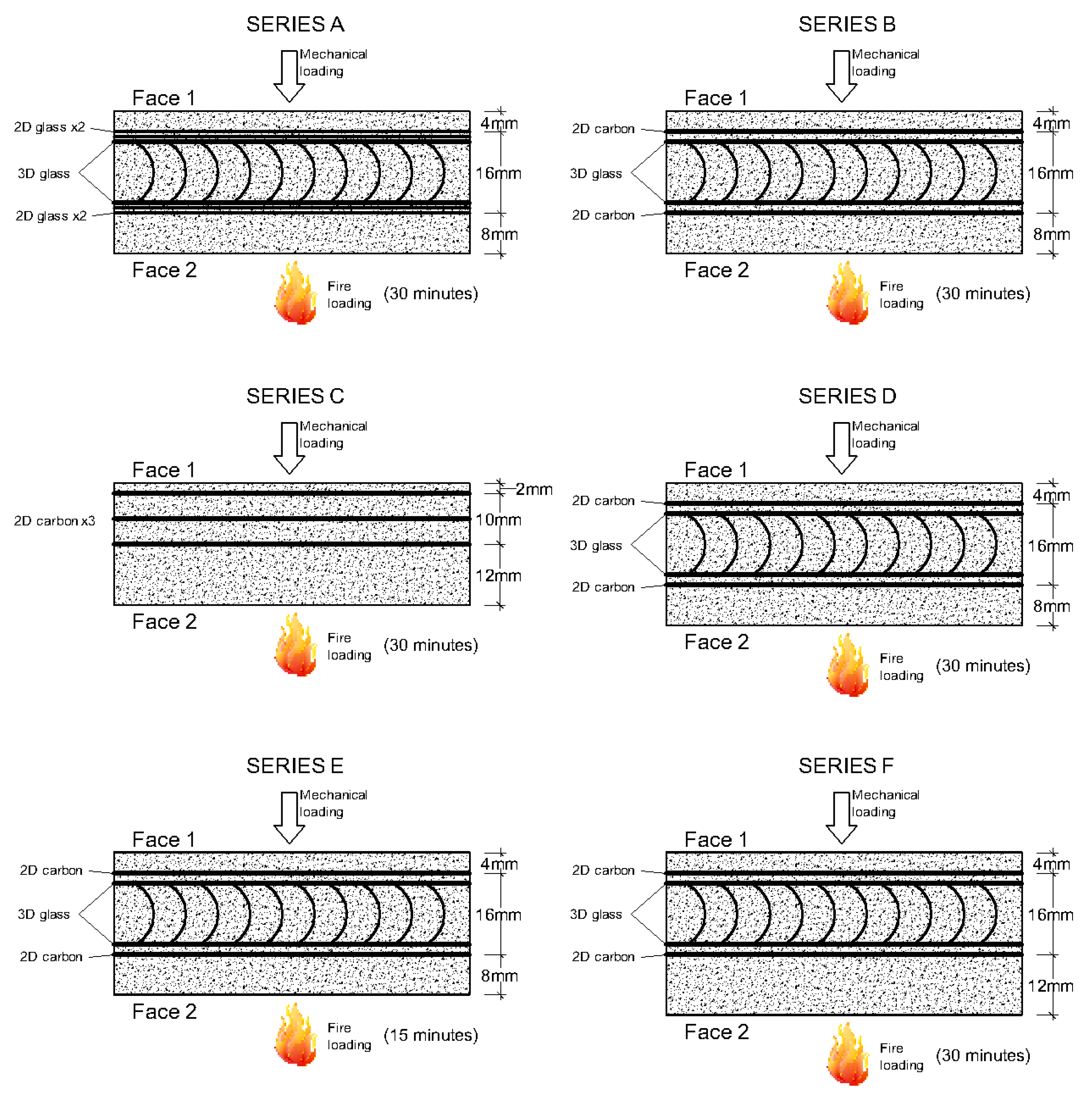
Three types of commercially available textiles have been used for this study, all consisting of coated glass or carbon fibers. A description of their properties is given next.
Two-dimensional (2D) glass styrene-butadiene (SBR) coated: Two-dimensional AR-glass textile with styrene-butadiene (SBR) coating (Figure 1a). The mesh size was equal to 12 mm in both directions and the weight of the textile before and after coating was equal to 568 g/m2 and 653 g/m2, respectively, according to the technical datasheet obtained from the provider.
Three-dimensional (3D) glass SBR coated: Three-dimensional AR-glass textile with styrene-butadiene coating (Figure 1b). The mesh size differed among the two perpendicular directions and the two faces, being 10 mm for the front face (face 1) and either 9 or 18 mm at the back face (face 2). However, the cross- sectional area of the reinforcement was equal in both faces: 70.5 mm2/m lengthways and 71.6 mm2/m crossways. The weight of the textile before and after coating is 917 g/m2 and 1055 g/m2, respectively. The distance between the two faces is 12 mm. The distance holders were made of polyester and were randomly curved; thus, their purpose was to hold the two layers of glass textiles at the specified distance and not to provide extra mechanical performance.
2D carbon SBR coated: Two-dimensional carbon textile with styrene-butadiene coating (Figure 1c). The mesh size was equal to 12.7 mm in both directions and the weight of the textile before and after coating was equal to 516 g/m2 and 578 g/m2, respectively.
Useful technical information about the textiles is summarized in Table 1.

2.3. Specimens

In total, six series of specimens were casted. Each series (consisting of six identical specimens) was made in order to investigate the influence of a different parameter. The parameters that were investigated are the following:
  • Thickness of the concrete cover
  • Time/temperature of exposure to fire
  • Material of fibers
  • Moisture content
The specimens were exposed to fire from only one side (referred to as “face 2”). The same side (face 2) was the one that was subjected to tension during the bending tests.
Each one of the series was casted as a plate of TRC of dimensions 500 mm × 435 mm (and a varying thickness according to the design of each case). After being cured at 20 °C and in a wet environment for 28 days, each plate was cut into six identical specimens of dimensions 500 mm × 70 mm, three of which were tested in bending without being subjected to a fire test, while the other three were tested in bending after being exposed to fire (the set-up of the fire tests is described in the next paragraph). In all cases, at least six yarns were present over the width of 70 mm, while these dimensions comply with the dimensional norm for testing TRC in tension, as per [30].
The differences between the geometry, the reinforcement and the duration of the fire test are provided in Figure 2.
It is also noted that all the specimens were dried in a furnace before being subjected to the fire test. The drying process consisted of successive heating (up to 104 °C) and weighting of the specimens until the weight was constant. This corresponds to 0% of moisture content. Series D was the exception to this, as it was first submerged in water until it was saturated with water (also defined after successive weighting until constant weight), which corresponds to 100% of moisture content. Eventually, specimens in Series D were dried in the same oven and by the same process, until the moisture content reached 50%.
The most important geometrical data for all the specimen Series are summarized in Table 2.
It should be noted that:
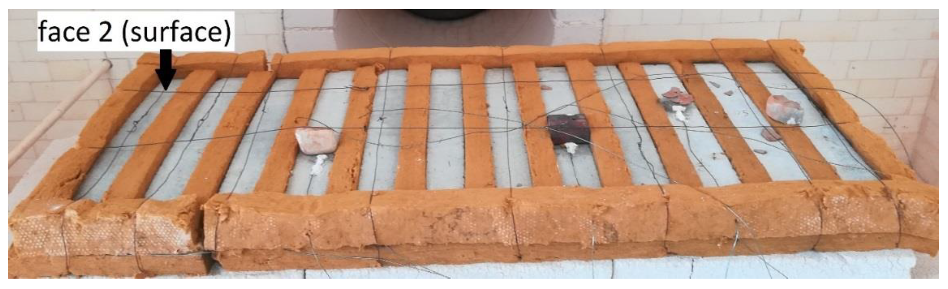
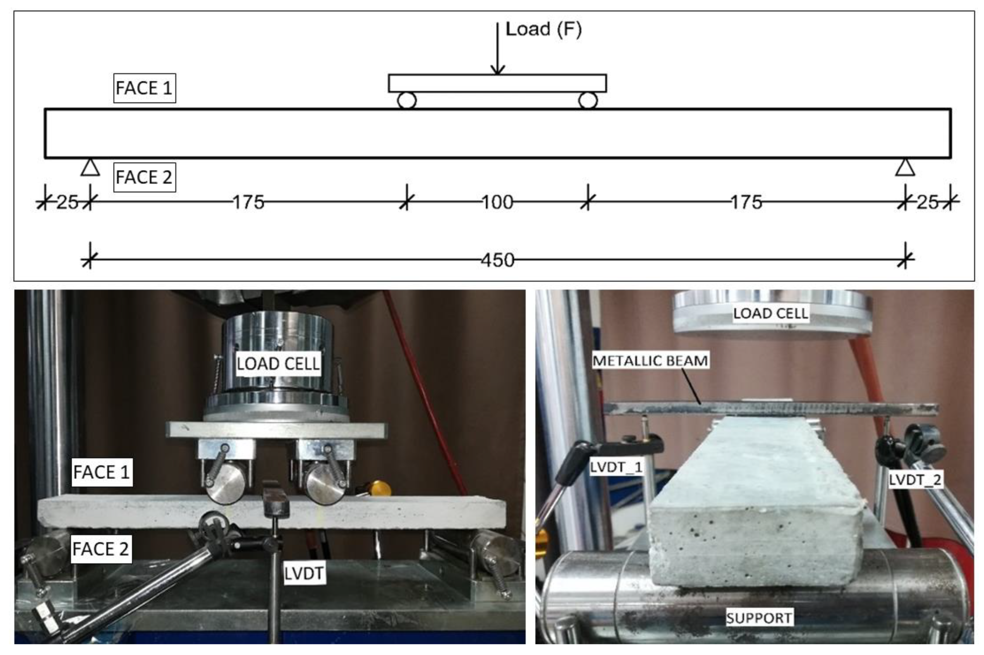
  • Face 2 is the face that was exposed to the fire during the fire test (also referred to as “surface” for the fire test). It is also the face that was subjected to tension during the bending test.
  • Effective depth refers to the level of the most stressed fibers (starting from face 1) during the bending test. Thus, it is also the level of fibers which were closer to the exposed to fire surface, which are the fibers that were exposed to the highest temperature.
  • Fiber volume fraction (Vf) was calculated only in the longitudinal direction of the specimens, in the direction of the tensile stresses during the bending test.

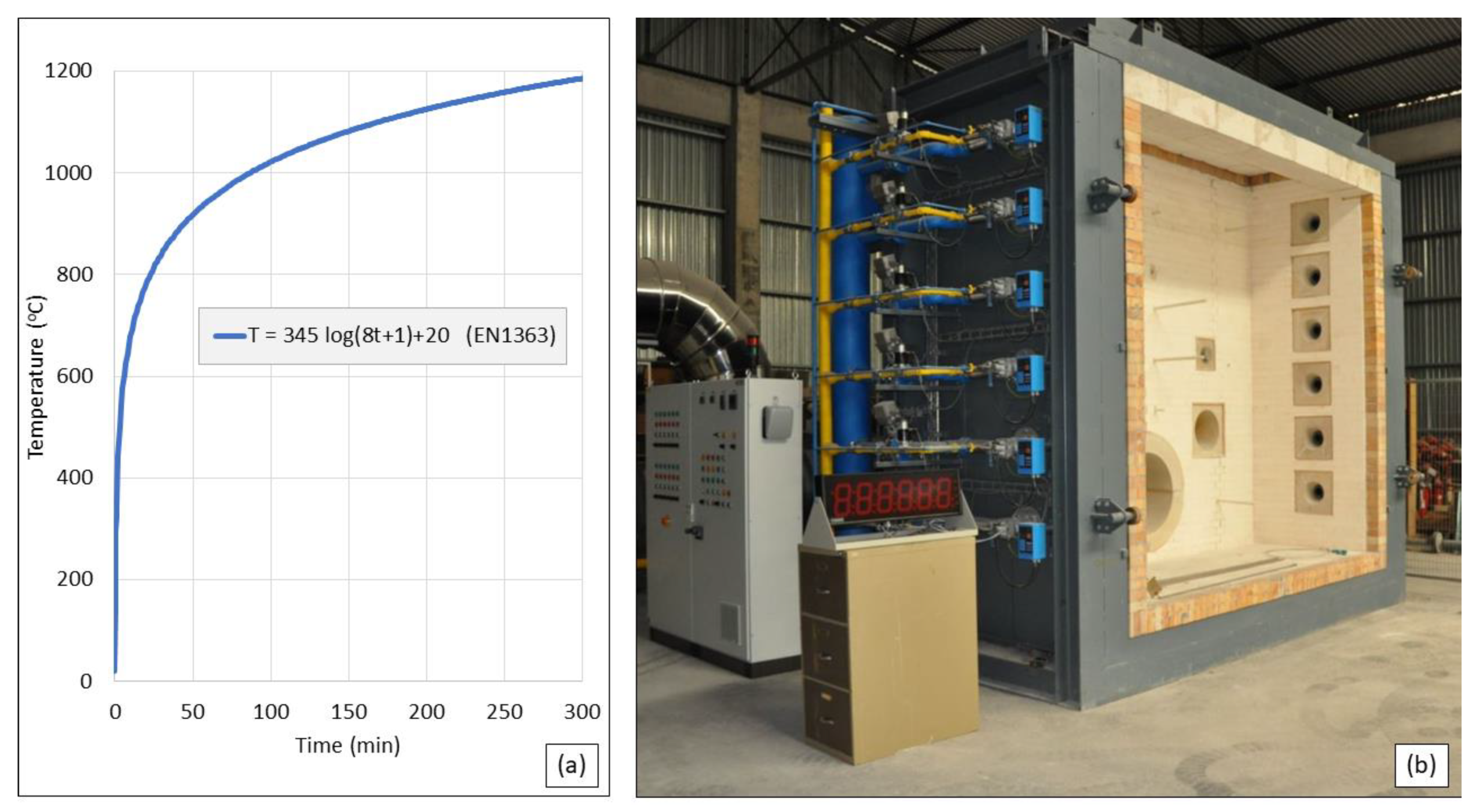
2.4. Fire Tests Set-up

For the fire tests, the standard fire curve given by EN 1363-1 was utilized. The fire curve was reproduced by the vertical furnace of the Fire Testing Facility at the University of Patras, Greece (see Figure 3).
As is apparent from Table 2, the specimens were not tested all at once but in several fire tests, for practical reasons such as different durations of exposure to fire, limited number of temperature sensors or due to the uncertainty of the expected residual strength and, thus, the possibility to re-evaluate and change the design of the specimens.
The sides of the specimens that were not directly exposed to fire were protected by using mineral wool, which is a fire-resistant insulating material. The insulation was tightened on the specimens using metallic wire (see Figure 4).
The temperature was measured with the use of thermocouples that were placed on the surface, in the middle and at the bottom of the specimens. The edge of the thermocouples placed at the surface was covered for a few millimeters with ceramic wool (which is thermally insulating and fire-resistant), in order to avoid being affected by the air temperature. The thermocouples in the middle were fixed inside a small cavity that was drilled a few days after unmolding the specimens. The thermocouples at the bottom were placed between the mineral wool and the specimens.

2.5. Mechanical Tests Set-up

The specimens were subjected to four-point bending according to Figure 5. The mechanical behavior (residual strength and stiffness) of the specimens that were subjected to the fire test was compared to the behavior of identical (control) specimens that were not subjected to fire. The results gave a good insight about the degradation of the specimens.
The value of the applied load was measured directly from the load cell that was fixed on the testing machine. A spherical metallic insert with three degrees of rotational freedom was attached between the load cell and the specimen, to eliminate the influence of geometrical imperfections. The testing method was displacement controlled, with a rate of 1 mm/min. The deflection of the specimens was measured in the middle of their span using two Linear Variable Differential Transformers (LVDTs), one on each side, in order to take into account any displacements due to possible torsional rotation of the specimens. A stiff metallic beam was fixed at the top of the specimens, exactly at the middle section, and the LVDTs were taking measurements with respect to this beam.

3. Results and Discussion

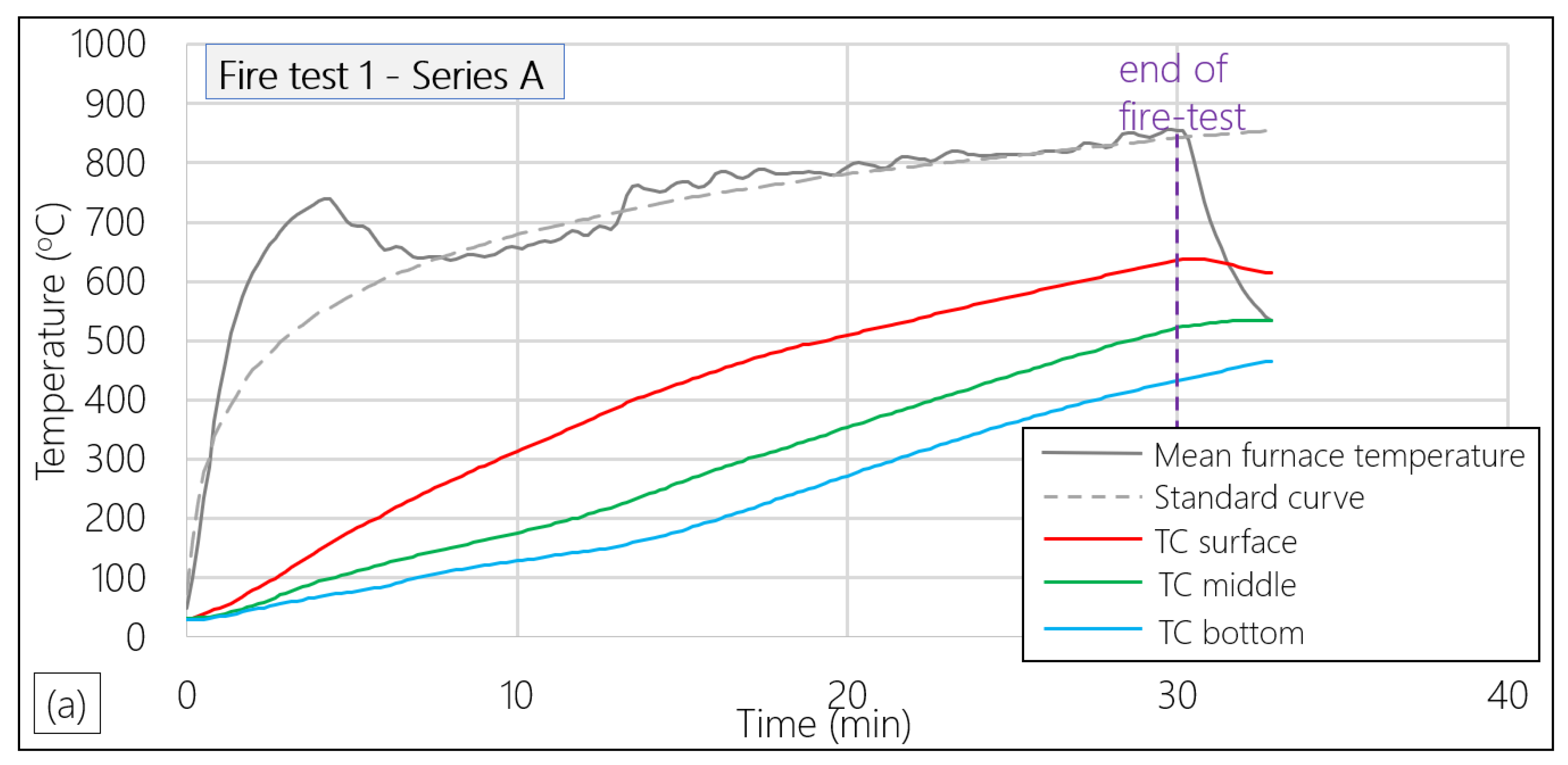
3.1. Fire-Testing Results

As described in the previous paragraph, the specimens were not tested all at once, but rather in the following fire tests:
  • Fire test 1: Series A was tested for a duration of 30 min.
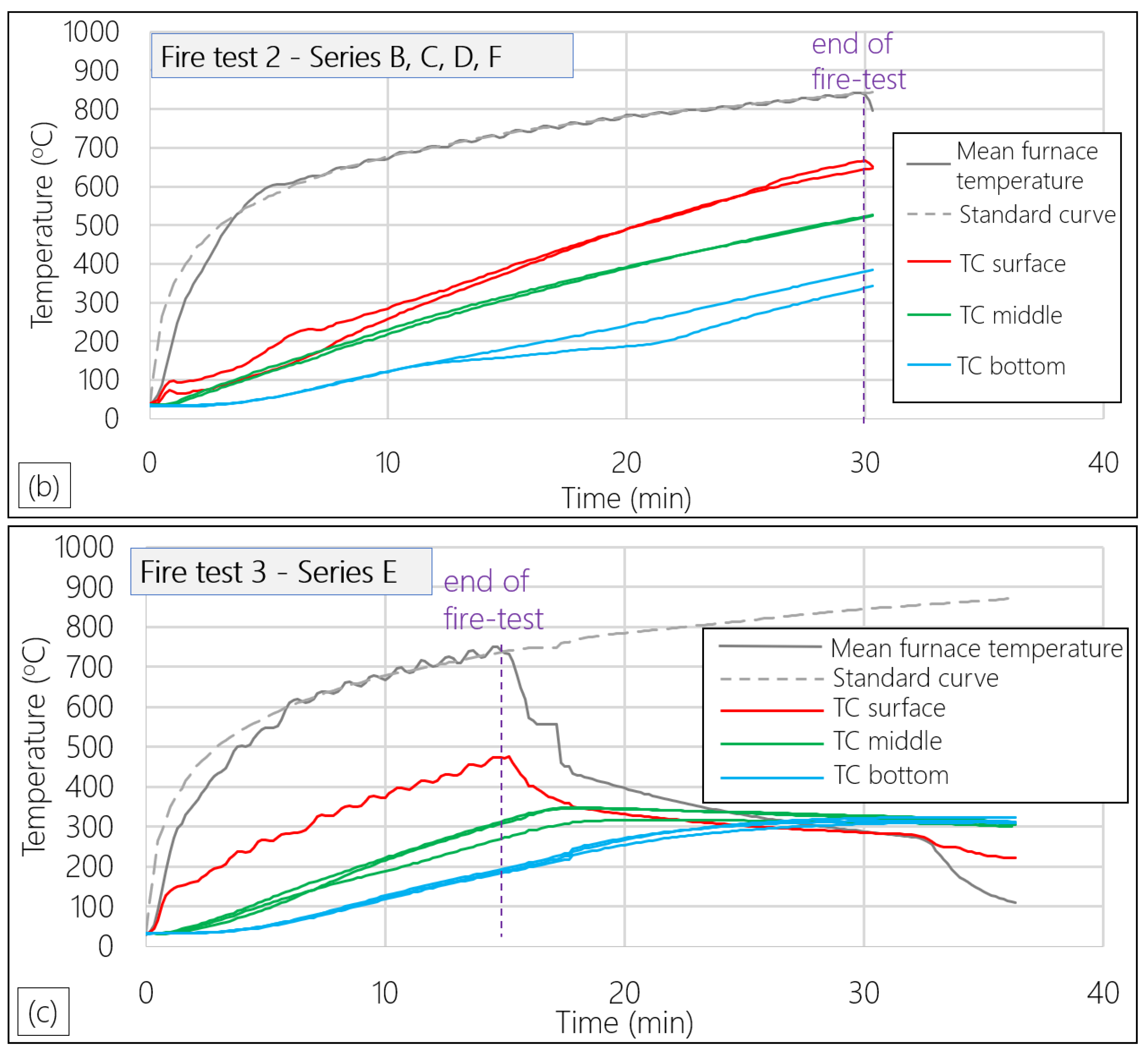
  • Fire test 2: Series B, C, D and F were tested for a duration of 30 min.
  • Fire test 3: Series E was tested for a duration of 15 min.
In the previous paragraph, it was mentioned that nine thermocouples were used in each fire-test to monitor the temperature on the specimens (three sensors on the surface of the specimens, three in the middle and three at the bottom). However, due to failure of the specimens or the fixing of the sensors, not all measurements recorded could be trusted. Therefore, in the next figures and tables (Figure 6 and Table 3), only the most reliable measurements are presented.
Additionally, it should be noted that since it was not possible to apply thermocouples in all specimens and all positions (also some of the applied thermocouples failed to give trustworthy measurements), some values of measured temperatures could be estimated based on the similar geometry of all the specimens. As a result, Table 3 is filled with values that were actually measured (normal fonts) or could be safely estimated (bold fonts).

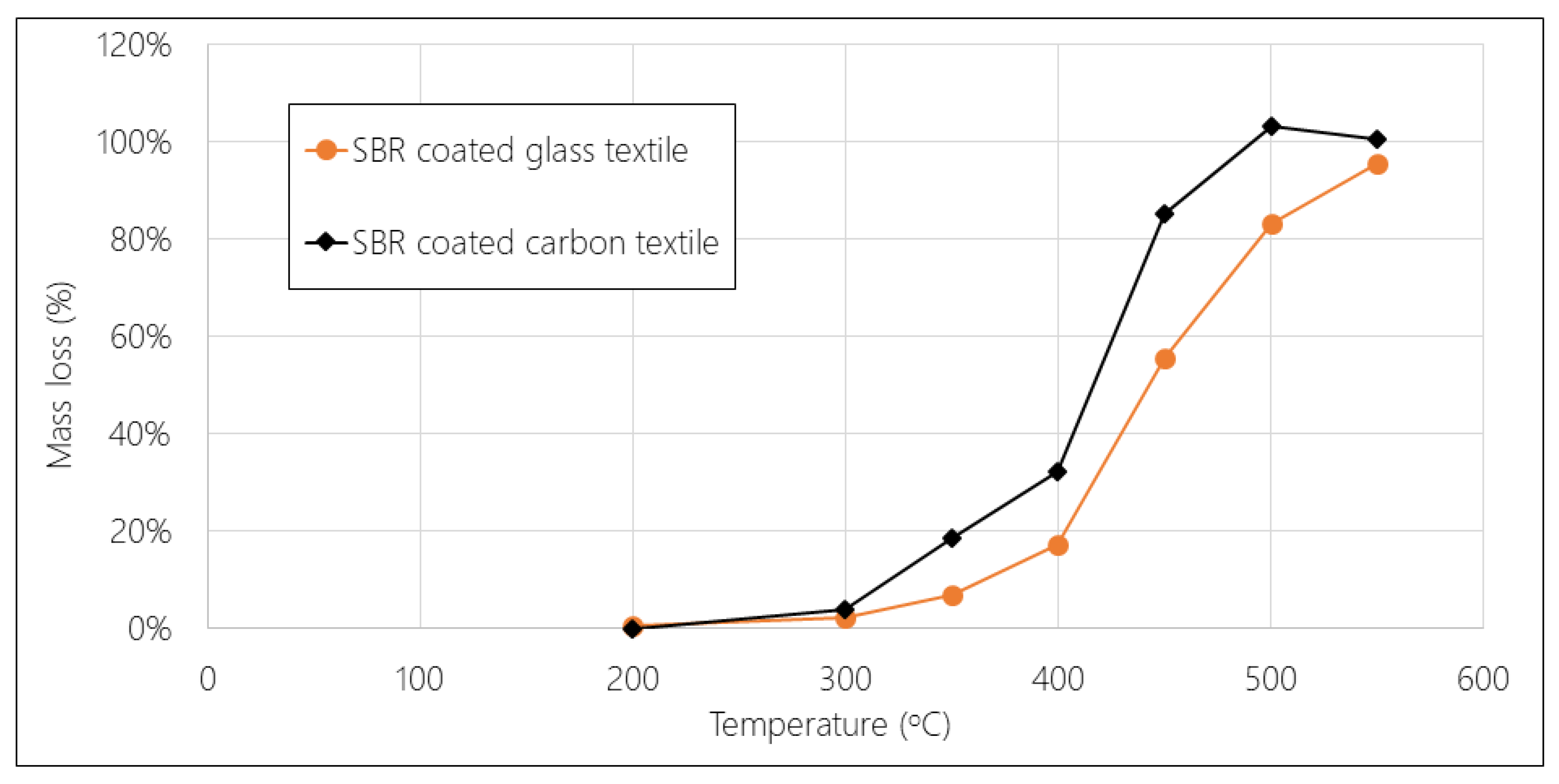
3.2. Results from Coating Burn-off Tests

The most critical parameter seems to be the failure of the bond between the matrix and the reinforcement, which is caused by the coating burn-off. Thus, some additional tests were performed, where samples of textiles were exposed to several temperatures and their weight was measured before and after exposure. Thus, the mass loss of the coating could be calculated.
It is important to note that:
  • The equipment that was used was a small electrical furnace with the capacity to reach 1000 °C.
  • Apart from the temperature, the time of exposure also plays a significant role. The heating rate in the middle of the specimens (closest measurement to the level of the effective depth, thus, the fibers that are of interest) was almost the same in both the 15-min and the 30-min fire tests, equal to 18–19 °C/min. Therefore, the heating time was decided each time according to the target temperature and a standard heating rate of 18 °C/min.
  • The cooling down of the specimens, after reaching the maximum temperature, was performed with a rate of 1.5 °C/min until a temperature of 200 °C, which is also a good approach of the cooling down rate that was measured at the 15-min fire test.
  • The initial mass of the coating was calculated based on the weight of the textiles before and after coating, as provided by the technical datasheets.
From the results which are presented in Figure 7, it was observed that the critical temperature after which the mass loss is becoming significant is close to 300 °C. It was also observed that after 500 °C, the coating was almost completely burnt-off.

3.3. Results from TRC Heating and Compression Tests

Since the degradation of the matrix due to the exposure to high temperatures also plays a significant role in the specimens’ mechanical response, some heating and compression tests were also performed on TRC specimens. This was chosen to be done on specimens of TRC rather than plain mortar, since the existence of the textiles might affect the compressive strength of the TRC sample even in ambient temperatures. This is because the interface between the concrete cover and the core of the element, where the textiles are placed, is a weak area in compression. Therefore, there is a chance that the failure will occur faster by spalling of the cover due to the weak connection of the cover to the core. This was actually observed, because the compressive strength of the TRC specimens was lower (by 20 MPa) than the compressive strength of the plain mortar specimens (see Paragraph 2.1). However, the shape and the dimensions of these specimens were different from the ones in the specimens of plain mortar (see Paragraph 2.1), which explains the difference in the measured strength.
The dimensions of these specimens were 70 × 110 × 28 mm. The loading direction was parallel to the height of 110 mm. Thus, the loaded cross section of 70 × 28 mm is the same as the cross section of the specimens subjected to bending. The applied load was given by the loading cell of the testing machine, while the deformation of the specimens was monitored by Digital Image Correlation, and thus, the strain and the elastic modulus were obtained.
Figure 8 gives the degradation of the TRC specimens due to heating at several temperatures, both in terms of strength and elastic modulus.
In Table 4, the reduction of the compressive strength and the elastic modulus at each elevated temperature is given in percentage, with the specimens in ambient temperature as reference.

3.4. Bending Tests Results

As it has been mentioned, three specimens of each series were tested in bending without being subjected to fire test and three specimens were tested after being exposed to fire. In this paragraph, the results from these tests are presented and discussed.

3.4.1. Results from 15-Minute Fire Tests

The only case where the specimens with SBR coated textiles presented a countable residual strength was the 15-min fire test. Even though the temperature at the level of the effective depth was not measured, by assuming a linear reduction of the temperature between the surface and the middle (where the temperatures are known), it was deduced that the temperature at the level of the effective depth was below 400 °C. However, as a precise calculation cannot be made, no numerical value is provided. Taking this estimation into account, it is not expected to have a severe degradation of the specimens of Series E, for the following reasons:
  • The mass loss of the coating is in the order of 20% or lower (see Figure 7); therefore, since most of the coating is still in place, the bond between the textiles and the mortar will not be completely lost as in Series A, B, C, D and F.
  • Even though it is well-known that glass fibers lose their strength after being exposed to temperatures higher than 300 °C, it is also well known that carbon fibers maintain their capacity to even higher temperatures if they are not in oxidizing atmosphere [31]. Therefore, even though the glass fibers within the specimens of Series E do not provide significant load bearing capacity, the carbon fibers do.
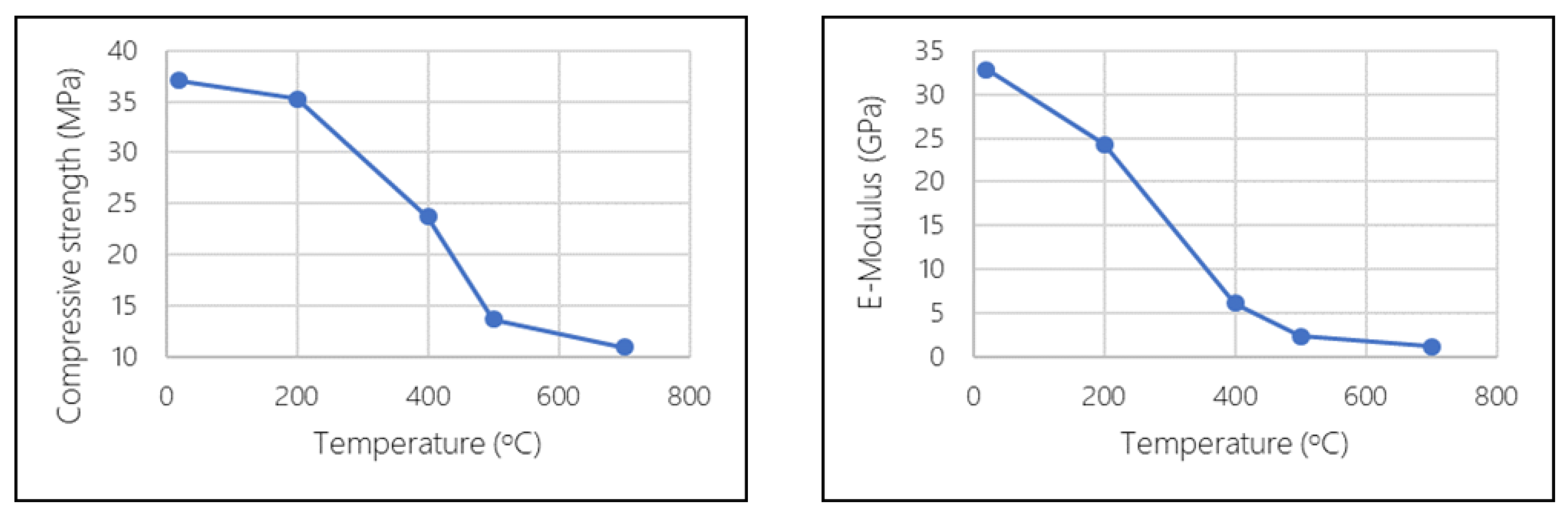
  • The matrix was exposed to a maximum temperature of 477 °C at the surface (face 2), while at the bottom side (face 1, which is subjected in compression at the flexural test, thus, it is the most contributing part of the mortar) the maximum temperature reached 317 °C. According to Table 4, the degradation of the mortar is also not critical. The loss of compressive strength is close to 20% (interpolation between 5% and 36%), while the reduction of the elastic modulus is close to 48% (interpolation between 23% and 72%).
Figure 9 gives the comparison between the load-bearing capacity of the not subjected and the subjected to fire testing specimens in Series E. In the same figure the dashed lines correspond to the specimens that were tested “upside-down”, which means that instead of having face 2 subjected to tension during bending, they had face 1. Additionally, for the specimen that was subjected to the fire test before the flexural test, it was again face 1 instead of face 2 that was directly exposed to fire. The reason why this happened was the difference in the concrete cover, since the specimens in Series E had a cover of 8 mm at face 2 and a cover of 4 mm at face 1. Of course, the effective depth during bending changed; thus, these two specimens cannot be compared to the others regarding their flexural strength (higher effective depth, and thus, higher flexural strength, as can be seen from the result of the not exposed specimen–the blue dashed line). However, it can be observed that the reduction of the load recorded for the exposed to fire specimen is greater than the respective reduction in the other specimens (not tested “upside down”–continuous blue lines). This is not surprising, because the concrete cover in the former case was smaller, thus, a heavier damage was done to the textiles at the level of the effective depth, as a result of the higher temperature reached. Therefore, it is logical that even though the not exposed, “upside-down” specimen (E3) has a higher strength than the other not exposed specimens (E1 and E2); this does not happen for the exposed-to-fire specimens (E6 is not stronger than E4 and E5).
Regarding Specimens E1, E2, E3 and E4, the initial and the post-cracking stiffness (k1 and k2, respectively) were calculated. Additionally, the maximum force (Fmax) and the corresponding displacement δmax were found. Eventually, the values of k1, k2, Fmax and δmax for the exposed and not exposed to fire specimens were compared and the degradation was calculated. The results can be seen in Table 5.

3.4.2. Results from 30-Minute Fire Tests

Regarding all specimens that were exposed to fire for 30 min, it can easily be derived from Table 3 that the temperature reached at the level of the effective depth (level of the most stressed fibers) was, in all cases, higher than 520 °C (since the temperature in the middle is around 520–530 °C and the effective depth was closer to the surface). During the subsequent bending tests, it was observed that the fibers started to pull-out at very low load levels, and that practically no residual strength was left (see Figure 10), even though no severe cracks or spalling of the cover was observed. It was obvious that the coating of the textiles, being a thermoplastic material, had been completely burnt-off, and thus, the bond between the textiles and the mortar had already failed before the test. As a matter of fact, the fibers could be pulled out of the specimens even bare-handedly (see Figure 11b). Coating burn-off tests showed that the SBR coating used was almost completely burnt-off after reaching 500 °C (see Figure 7).
Figure 10 gives the comparison of the load-bearing capacity of the not subjected and the subjected to fire testing specimens in Series A. Similar results were observed for Series B, C, D and F; therefore, the graphs for those series are not presented. No conclusions can be drawn regarding the effect of the nature of the fibers or the moisture content of the specimens.
Additionally, it is worth mentioning that specimens in Series C and F developed a residual curvature after the fire testing (Figure 11a). These two series were characterized by a high geometrical asymmetry, as can be seen from Figure 2. Due to this asymmetry, the top layer (concrete cover of 12 mm), which was exposed to the high temperature and had no reinforcement, suffered from an increased thermal expansion. On the other hand, the bottom layer was subjected to lower temperatures and the textile that was concentrated near the bottom offered an increased axial stiffness to the lower part of the specimens. As a result, the thermal expansion was much lower at the bottom with respect to the top, which led to the curving of the specimens due to the thermal loading. The curvature was so intense that the surface was severely damaged (visible cracks). Thus, the damage, and therefore, part of the deformation, were irreversible (the specimens remained curved even after cooling down). The residual strength of these specimens was so low that two of them broke while being transferred from the furnace to the bending test set-up; thus, they were not tested at all. In addition, since no numerical results were obtained from testing these series, the effect of the increased concrete cover could not be quantified.
The conclusions that can be drawn from these results, are:
  • The temperature stability of the coating of the textiles seems to be the most decisive parameter regarding the residual strength of the TRC specimens, since it directly affects the bond between the matrix and the reinforcement. Thus, extra care must be given when thermoplastic coatings are used in applications with fire safety requirements.
  • The increased concrete cover could potentially protect the reinforcement better than a thinner cover; however, it is suggested that the same cover be applied symmetrically, so that a high geometrical eccentricity is avoided.

4. Conclusions

This paper investigated the thermomechanical behavior of textile reinforced cementitious composites subjected to elevated temperatures. The specimens were made of a cementitious matrix with quartz sand and technical textiles coated with styrene-butadiene coating. The heating of the specimens was achieved by one-sided exposure, utilizing a standard fire curve (temperature versus time), which was followed for 15 and 30 min, after which the specimens were cooled down naturally. Flexural tests were performed to heated and not heated specimens, to determine their structural degradation due to the high temperatures. Additionally, compressive tests were performed to heated and unheated TRC specimens, for the same purpose. Moreover, coating burn-off tests were performed to the textiles, to determine the mass loss of coating as a function of temperature. The basic conclusions are the following:
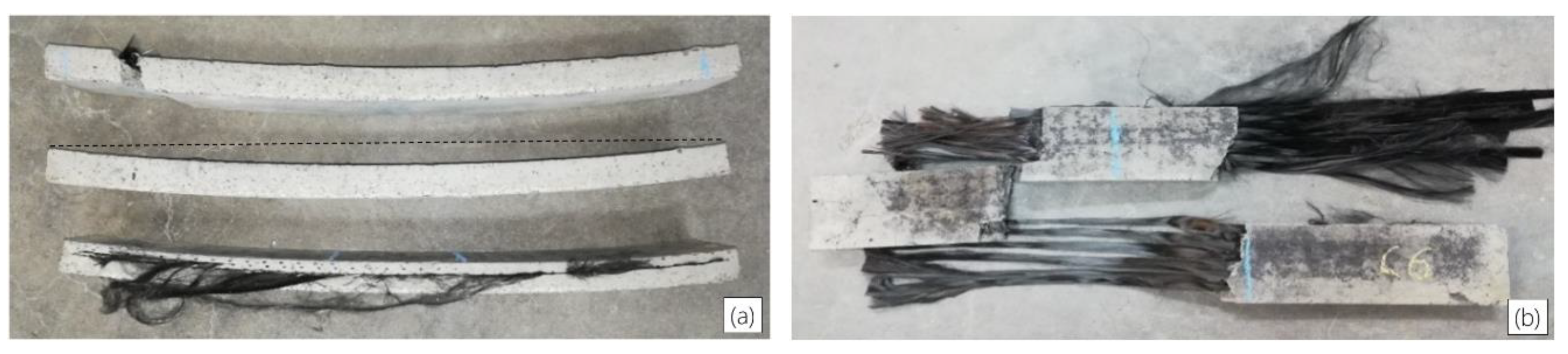
  • The most critical parameter that defines the residual strength of the TRC specimens after heating is the coating of the textiles. After the 15-min long fire test, where the temperature at the effective depth did not exceed 400 °C, the degradation was less severe, since the coating was not completely lost (less than 30%). The specimens in this case contained hybrid reinforcement of glass and carbon textiles and they suffered reductions of 74% and 48% in the initial and the post-cracking stiffness, respectively. The maximum force also dropped by 25%, while the corresponding maximum displacement increased by 68%.
  • The textiles that were coated with a thermoplastic material retained a practically negligible residual strength after being subjected to a 30-min fire test, where the temperature at the level of the effective depth (most stressed fibers during the bending test) exceeded 500 °C. This corresponds to a mass loss of 90% or higher and is explained by the fact that the loss of the coating, which is an intermediate layer between the fibers and the matrix, leads to failure of the bond between the fibers and the matrix. The same result was observed regardless of the fiber material (glass or carbon), the thickness of the concrete cover (8 mm or 12 mm) and the moisture saturation of the specimens (0% or 50%).
  • The degradation of the mortar due to the high temperature was also significant and could be another dominant parameter. Regarding the compressive strength and the elastic modulus, it was observed that the latter dropped faster with respect to the temperature of exposure. However, in both cases the degradation was not severe until 200 °C (5% and 23%, respectively), while it became critical at 500 °C (63% and 82% loss, respectively).
  • The temperature profile within the cross section of the one-sided exposed specimens of TRC was not uniform. Specifically, the temperature reduction through the top part of the specimens appeared to be higher due to the lower thermal conductivity of the top, hotter, layers. Thus, the concrete cover is also a potential critical parameter that could determine the residual strength of the heated specimens. The effect of the concrete cover, though, was not quantified in this study.
  • Finally, it was concluded that a highly asymmetrical design scheme can be disastrous for the case of one-sided exposure to fire, since the double asymmetry (in heating and in axial stiffness) can lead to premature failure of the specimens solely due to thermal stresses.

Author Contributions

Conceptualization, P.K., T.T. (Thanasis Triantafillou) and T.T. (Tine Tysmans); Investigation, P.K. and M.E.K.; Methodology, J.W., T.T. (Thanasis Triantafillou) and T.T. (Tine Tysmans); Supervision, T.T. (Thanasis Triantafillou) and T.T. (Tine Tysmans); Writing—original draft, P.K.; Writing—review & editing, M.E.K., J.V., M.D.M., J.W., T.T. (Thanasis Triantafillou) and T.T. (Tine Tysmans).

Funding

This research was funded by the Agentschap voor Innovatie en Ondernemen (VLAIO), grant number IWT140070, and partially by the Structural Materials Laboratory at the University of Patras.

Acknowledgments

The authors gratefully all the members of the ‘CeComStruct’ project, of which this research is part of, for their advice. The authors would also like to thank the company ‘Sika Hellas’ for the donation of the cementitious material that was used in this research. Finally, the authors would like to acknowledge the priceless help of the laboratory technician Kyriakos Karlos for the laborious experimental work.

Conflicts of Interest

The authors declare no conflict of interest.

References

  1. Hothan, S.; Ehlig, D. Reinforced concrete slabs strengthened with textile reinforced concrete subjected to fire. In Proceedings of the 2nd International RILEM Work Concrete Spalling Due to Fire Exposure, Delft, The Netherlands, 5–7 October 2011; RILEM Publications: Bagneux, France, 2011; pp. 419–426. [Google Scholar]
  2. Hashemi, S.; Al-Mahaidi, R. Experimental and finite element analysis of flexural behavior of FRP-strengthened RC beams using cement-based adhesives. Constr. Build. Mater. 2012, 26, 268–273. [Google Scholar] [CrossRef]
  3. Bisby, L. Design for fire of concrete elements strengthened or reinforced with fibre-reinforced polymer: State of the art and opportunities from performance-based approaches. Can. J. Civ. Eng. 2013, 40, 1034–1043. [Google Scholar] [CrossRef]
  4. Michels, J.; Zwicky, D.; Scherer, J.; Harmanci, Y.E. Structural strengthening of concrete with fiber reinforced cementitious matrix (FRCM) at ambient and elevated temperature—Recent investigations in Switzerland. Adv. Struct. Eng. 2014, 17. [Google Scholar] [CrossRef]
  5. Tetta, Z.C.; Bournas, D.A. TRM vs FRP jacketing in shear strengthening of concrete members subjected to high temperatures. Compos. Part B 2016, 106, 190–205. [Google Scholar] [CrossRef] [Green Version]
  6. Raoof, S.M.; Bournas, D.A. TRM versus FRP in flexural strengthening of RC beams: Behaviour at high temperatures. Constr. Build. Mater. 2017, 154, 424–437. [Google Scholar] [CrossRef]
  7. Raoof, S.M.; Bournas, D.A. Bond between TRM versus FRP composites and concrete at high temperatures. Compos. Part B Eng. 2017, 127, 150–165. [Google Scholar] [CrossRef]
  8. Ombres, L. Analysis of the bond between Fabric Reinforced Cementitious Mortar (FRCM) strengthening systems and concrete. Compos. Part B Eng. 2015, 69, 418–426. [Google Scholar] [CrossRef]
  9. Triantafillou, T.; Karlos, K.; Kefalou, K.; Argyropoulou, E. An innovative structural and energy retrofitting system for masonry walls using textile reinforced mortars combined with thermal insulation. RILEM Bookser. 2018, 15, 752–761. [Google Scholar]
  10. Maroudas, S.R.; Papanicolaou, C.G. Effect of High Temperatures on the TRM-to-Masonry Bond. Key Eng. Mater. 2017, 747, 533–541. [Google Scholar] [CrossRef]
  11. Ombres, L.; Iorfida, A.; Mazzuca, S.; Verre, S. Bond analysis of thermally conditioned FRCM-masonry joints. Measurement 2018, 125, 509–515. [Google Scholar] [CrossRef]
  12. Ehlig, D.; Jesse, F.; Curbach, M. High temperature tests on textile reinforced concrete (TRC) strain specimens. In Proceedings of the International RILEM Conference on Material Science (MatSci), Aachen, Germany, 6–8 September 2010. [Google Scholar]
  13. Hegger, J.; Horstmann, M.; Zell, M. Applications for TRC. In Proceedings of the 15th International Congress of the GRCA, Prague, Czech Republic, 20–23 April 2008. [Google Scholar]
  14. Rambo, D.A.; Silva, F.D.A.; Filho, R.D.T.; Ukrainczyk, N.; Koenders, E. Tensile strength of a calcium-aluminate cementitious composite reinforced with basalt textile in a high-temperature environment. Cem. Concr. Compos. 2016, 70, 183–193. [Google Scholar] [CrossRef]
  15. Silva, F.D.A.; Butler, M.; Hempel, S.; Filho, R.D.T.; Mechtcherine, V. Effects of elevated temperatures on the interface properties of carbon textile-reinforced concrete. Cem. Concr. Compos. 2014, 48, 26–34. [Google Scholar] [CrossRef]
  16. Xu, S.; Shen, L.; Wang, J. The high-temperature resistance performance of TRC thin-plates with different cementitious materials: Experimental study. Constr. Build. Mater. 2016, 115, 506–519. [Google Scholar] [CrossRef]
  17. Ward, M.; Bisby, L.; Stratford, T.; Roy, E. Fibre Reinforced Cementitious Matrix systems for fire-safe flexural strengthening of concrete: Pilot testing at ambient temperatures. In Proceedings of the 4th International Conference on Advanced Composites in Construction, Chesterfield, UK, 3–5 September 2009; NetComposites Ltd.: Chesterfield, UK, 2009; pp. 449–460. [Google Scholar]
  18. Donnini, J.; Basalo, F.D.C.; Corinaldesi, V.; Lancioni, G.; Nanni, A. Fabric-reinforced cementitious matrix behavior at high-temperature: Experimental and numerical results. Compos. Part B Eng. 2017, 108, 108–121. [Google Scholar] [CrossRef]
  19. Çavdar, A. A study on the effects of high temperature on mechanical properties of fiber reinforced cementitious composites. Compos. Part B Eng. 2012, 43, 2452–2463. [Google Scholar] [CrossRef]
  20. Caverzan, A.; Colombo, M.; di Prisco, M.; Rivolta, B. High performance steel fibre reinforced concrete: Residual behaviour at high temperature. Mater. Struct. 2015, 48, 3317–3329. [Google Scholar] [CrossRef]
  21. Colombo, I.; Colombo, M.; Magri, A.; Zani, G.; Di Prisco, M. Textile reinforced mortar at high temperatures. Appl. Mech. Mater. 2011, 82, 202–207. [Google Scholar] [CrossRef]
  22. Rambo, D.A.S.; Silva, F.D.A.; Filho, R.D.T.; Da Gomes, O.F.M. Effect of elevated temperatures on the mechanical behavior of basalt textile reinforced refractory concrete. Mater. Des. 2015, 65, 24–33. [Google Scholar] [CrossRef]
  23. Rambo, D.A.S.; Yao, Y.; Silva, F.D.A.; Filho, R.D.T.; Mobasher, B. Experimental investigation and modelling of the temperature effects on the tensile behavior of textile reinforced refractory concretes. Cem. Concr. Compos. 2017, 75, 51–61. [Google Scholar] [CrossRef]
  24. Nguyen, T.H.; Vu, X.H.; Si Larbi, A.; Ferrier, E. Experimental study of the effect of simultaneous mechanical and high-temperature loadings on the behaviour of textile-reinforced concrete (TRC). Constr. Build. Mater. 2016, 125, 253–270. [Google Scholar] [CrossRef]
  25. Keleştemur, O.; Arıcı, E.; Yıldız, S.; Gökçer, B. Performance evaluation of cement mortars containing marble dust and glass fiber exposed to high temperature by using Taguchi method. Constr. Build. Mater. 2014, 60, 17–24. [Google Scholar] [CrossRef]
  26. Reinhardt, H.W.; Kruger, M.; Raupach, M. Behavior of textile-reinforced concrete in fire. ACI Spec. Publ. 2008, SP250, 99–100. [Google Scholar]
  27. Antons, U.; Hegger, J.; Kulas, C.; Raupach, M. High-temperature tests on concrete specimens reinforced with alkali-resistant glass rovings under bending loads. In Proceedings of the 6th International Conference on FRP Composites in Civil Engineering, Rome, Italy, 13–15 June 2012. [Google Scholar]
  28. Buttner, R.M.; Orlowsky, J.; Raupach, M. Fire Resistance Tests of Textile Reinforced Concrete under Static Loading—Results and Future Developments, Proceedings of the 5th International RILEM Workshop on High Performance Fiber Reinforced Cement Composites, Mainz, Germany, 10–13 July 2007; Reinhardt, H.W., Naaman, A.E., Eds.; RILEM Publications: Bagneux, France, 2014. [Google Scholar]
  29. BS EN 1363-1:1991. Fire Resistance Tests—Part 1: General Requirements; British Standards Institution (BSI): London, UK, August 1991. [Google Scholar]
  30. Brameshuber, W. (RILEM Technical Committee). Recommendation of RILEM TC 232-TDT: test methodsand design of textile reinforced concrete. Uniaxial tensile test: test method to determine the load bearing behavior of tensile specimens made of textile reinforced concrete. Mater. Struct. 2016, 49, 4923–4927. [Google Scholar]
  31. Triantafillou, T. Textile Fibre Composites in Civil Engineering; Woodhead Publishing: London, UK, 2016; pp. 173–174. [Google Scholar]
Figure 1. (a) 2D styrene-butadiene (SBR) coated glass-fiber textile; (b) 3D SBR coated glass-fiber textile; (c) SBR coated carbon-fiber textile.
Applsci 09 00747 g001
Figure 2. Cross sectional geometry of specimen Series A to F.
Applsci 09 00747 g002
Figure 3. (a) Standard fire curve according to EN 1363-1; (b) Vertical furnace at the Fire Testing Facilities of the University of Patras (internal dimensions of 3 m × 3 m × 1.2 m).
Applsci 09 00747 g003
Figure 4. Set-up of specimens from Series B, C, D and F for the execution of the fire test. At the end of each fire test, the specimens were left to cool down naturally, without getting them out of the furnace before reaching the room temperature. The door of the furnace was only opened after the temperature had dropped to 180 °C, to avoid sudden cooling down which could harm the specimens and the furnace itself.
Applsci 09 00747 g004
Figure 5. Experimental set-up details about the four-point bending tests.
Applsci 09 00747 g005
Figure 6. (a) Temperature measurements from fire test 1; (b) temperature measurements from fire test 2; (c) temperature measurements from fire test 3.
Applsci 09 00747 g006aApplsci 09 00747 g006b
Figure 7. Mass loss of the textiles’ coating after heating to different temperatures.
Applsci 09 00747 g007
Figure 8. Reduction of compressive strength and elastic modulus of textile reinforced concrete (TRC) specimens after exposure to elevated temperatures.
Applsci 09 00747 g008
Figure 9. Force versus displacement curves for specimens in Series E.
Applsci 09 00747 g009
Figure 10. Force versus displacement curves for specimens in Series A.
Applsci 09 00747 g010
Figure 11. (a) Curvature of specimens from the one-sided fire loading and the asymmetrical placement of the reinforcement; (b) specimen in Series C that was subjected to fire testing. The fibers were easily pulled out by hand after the flexural test of the specimen.
Applsci 09 00747 g011
Table 1. Geometrical and mechanical data of the reinforcing textiles.
Type of TextileRoving Distance (mm)Weight before Finishing (gr/m2)Nominal Thickness (mm)Yarn Failure Stress (MPa)Yarn Stiffness (GPa)
warpweftwarpweftwarpweft
Two-dimensional (2D) glass12122842840.1060.10652667
Three-dimensional (3D) glass
styrene-butadiene (SBR) coated
Face 11010229.3229.30.1710.17149667
Face 2189229.3229.30.1710.171
2D carbon SBR coated12.712.72582580.1430.14381493
Table 2. Geometrical data and testing parameters for Series A to F.
Fire TestSeriesType of ReinforcementCover Thickness (mm)Total Thickness (mm)Effective Depth (mm)Time of Exposure (min)Moisture Saturation (%)Fiber Volume Fraction (%)
Face 1Face 2
TEST 1AGlass4828203002.17
TEST 2BGlass + carbon4828203001.47
CCarbon21224123001.82
DGlass + carbon48282030501.47
FGlass + carbon41232203001.29
TEST 3EGlass + carbon 4828201501.47
Table 3. Temperature measurements from fire tests 1, 2 and 3.
Fire TestDuration (min.)SeriesTemperature at the End of the Fire Test (°C)
surfacemiddlebottom
130A638525437
230B648526343
C---
D650530343
F666524385
315E477302192
* Normal fonts: measured values; Bold fonts: estimated values.
Table 4. Reduction of compressive strength and elastic modulus of TRC after exposure to high temperatures.
Temperature (°C)Reduction of Compressive StrengthReduction of Elastic Modulus
20--
2005%23%
40036%72%
50063%82%
70071%85%
Table 5. Mechanical characteristics of specimens of Series E that were exposed or not exposed to fire.
Mechanical PropertiesNot Exposed Specimens (E1, E2)Exposed Specimens (E4, E5)Difference (%)
k1 (kN/m)1.580.41−74%
k2 (kN/m)0.200.10−48%
Fmax (kN)1.861.39−25%
δmax (mm)14.123.6+68%

