Article

Optimization Design and Analysis for a Single Motor Hybrid Powertrain Configuration with Dual Planetary Gears

1
The State Key Laboratory of Mechanical Transmission, Chongqing University, Chongqing 400044, China
2
Department of Automotive Engineering, Chongqing University, Chongqing 400044, China
*
Author to whom correspondence should be addressed.
Appl. Sci. 2019, 9(4), 707; https://doi.org/10.3390/app9040707
Submission received: 8 January 2019 / Revised: 11 February 2019 / Accepted: 12 February 2019 / Published: 18 February 2019
(This article belongs to the Special Issue Smart Home and Energy Management Systems 2019)

Abstract

:
To further improve the comprehensive operating performance of the single motor hybrid electric vehicle, a single motor hybrid powertrain configuration with dual planetary gears (SMHPC-2PG) design is proposed in this paper. By adopting a topology design method that characterizes the constraint relationship between power resource components and planetary gear (PG) nodes, all feasible configuration candidates based on the basic configuration scheme are systematically explored, and dynamic models of configuration candidates are automatically generated. The optimal fuel economy and dynamic performance for configuration candidates are simulated by applying the global optimal control strategy based on dynamic programming (DP). Results of this study demonstrate that SMHPC-2PG with excellent operating performance can be screened out by this method.

1. Introduction

With the increasingly stringent emission and fuel consumption regulations, major automobile manufacturers have stepped up the research and development of hybrid electric vehicle (HEV), which is a key technology for energy saving and emission reduction. Compared with a conventional fuel vehicle, the HEV can adopt electric energy to replace fossil fuels wholly or partially for driving when the engine is in the condition of low efficiency and high fuel consumption, which can improve fuel economy and reduce emissions [1,2,3].
In recent years, the HEV market has been dominated by the power-split hybrid electric vehicle with the function of an electric continuously variable transmission (ECVT) [4,5]. Both Toyota Hybrid System (THS) and GM (General Motors Corporation) Advanced Hybrid System (AHS) adopt the power-split hybrid powertrain configuration scheme [6,7,8,9]. By introducing clutch to change the way of combination and connection between PG nodes and power resource components, the power-split hybrid powertrain configuration possesses multiple operating modes, which greatly increases the probability of high-efficient operation for the vehicle. Therefore, the multi-mode power-split hybrid powertrain configuration based on planetary gear (PG) has enormous potential in improving fuel economy [10,11]. However, the flexible combination and connection of PG lead to a large number of configuration candidates, which make it difficult to simultaneously express the topology and functional characteristics and judge the feasibility and applicability of configurations. Therefore, it is a challenging task to search out excellent configurations in a large number of configuration candidates [12]. To overcome this issue, many scholars have carried out relevant research on the optimization of and screening for configuration schemes. Kim et al. optimized the all power-split configuration with single PG (PSC-1PG) by applying the lever method [13]. Similarly, Zhang et al. screened the PSC-1PG by adopting the method of increasing/decreasing clutch, and optimized the parameters of components [14]. Literatures [13,14] mainly use the simple model of lever mechanics to replace complex and changeable PG systems, which can intuitively express the connection between PG and power resource components. However, the lever method mainly extracts the dynamic equation of configuration by a manual approach. Therefore, it is almost impossible to employ the lever method to seriatim analyze the complex multi-PG configuration and obtain the optimal configuration. In view of this issue, literature [15] proposed a general matrix search method based on the internal connection relationship of PG and the state sequence of clutch. By employing this method, the power-split configuration with dual PGs (PSC-2PG) was searched completely, and the PSC-2PG with greater advantages in fuel economy was obtained. On the basis of literature [15], Zhuang et al. added the acceleration constraints to the above search method, searched the power-split configuration with three PGs (PSC-3PG) with the optimization objectives of fuel economy and dynamic performance, and pointed out that compared with the PSC-2PG, the PSC-3PG has an obvious advantage only in traction performance [16]. Therefore, in hybrid powertrain configuration based on PG, the introduction of dual PGs can maximize the improvement potential of configuration in fuel economy and other performances. Based on the idea of mode combination and superposition in the search process of configuration, literatures [15,16] provide a variety of operating modes for the hybrid powertrain configuration with multi-PG, which increases the probability of high-efficient operation for the vehicle. However, due to the discrete characteristics of the state sequence of clutch, it is necessary to seriatim analyze and classify the operating modes in the search process. In addition, literature [17] optimized the hybrid powertrain configuration by adopting a bond graph. Nevertheless, the completeness of configuration needs to be analyzed by employing assistant tools in the generation process of configuration, which makes the search process cumbersome. Compared with the above studies that optimize and screen configuration completely, literatures [18,19] mainly focus on the analysis and combination for specific operating modes to generate configuration schemes, which can narrow the search range and avoid the meaningless configurations that may occur during the search process, but cannot ensure the generation of the optimal configuration.
All the power-split hybrid powertrain configurations adopt two motors. In contrast, the single motor hybrid powertrain configuration has the advantages of simple structure, ease of control, and low cost. Therefore, many scholars have shifted their research focus to the single motor hybrid powertrain configuration. Sundström et al. studied the single motor hybrid powertrain configuration based on the connection relationship of the motor [20]. Furthermore, Debal et al. improved fuel economy by optimizing the component parameters of P2 and P3 configurations [21]. On the basis of P2 configuration, Sun et al. increased the system topology by introducing PG, which improved the fuel economy of the multi-mode P2 configuration [22]. At present, although some progress has been made in the research of the single motor hybrid powertrain configuration, the improvement potential for the existing single motor hybrid powertrain configuration in fuel economy is still limited [23,24].
To further improve the comprehensive operating performance of the single motor hybrid powertrain configuration, by combining the advantages of dual PGs configuration, the single motor hybrid powertrain configuration with dual planetary gears (SMHPC-2PG) is proposed in this paper. By applying a topology design method that characterizes the constraint relationship between power resource components and PG nodes, the dynamic models of all configuration candidates are automatically generated, and the output characteristics of configuration candidates are obtained. The optimal fuel economy and dynamic performance of configuration candidates are simulated by employing the global optimal control strategy based on dynamic programming (DP). The SMHPC-2PG with excellent comprehensive performance is obtained by comparing the performance.
The remainder of this paper is organized as follows: Section 2 depicts the basic configuration scheme of SMHPC-2PG and the topology design method. Section 3 presents powertrain parameters and component models. Section 4 formulates the global optimal control strategy, and screens all the configuration candidates based on this control strategy. Result and comparative analysis are discussed in Section 5. Finally, the conclusions are presented in Section 6.

2. Single Motor Hybrid Powertrain Configuration with Dual Planetary Gears

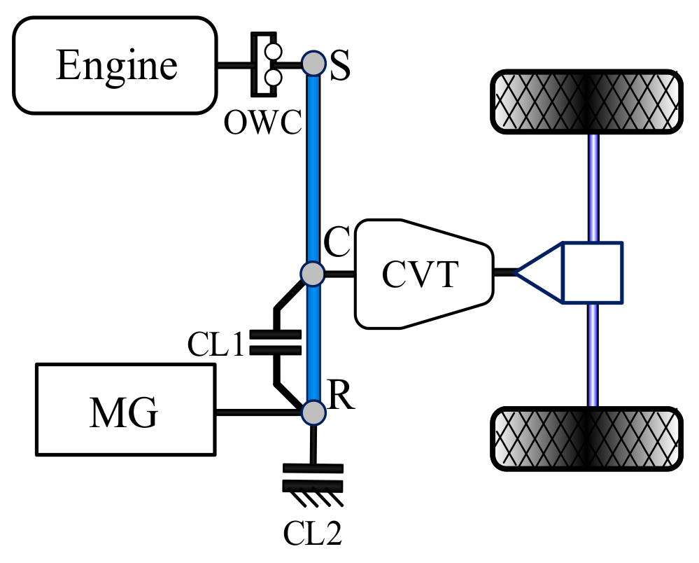
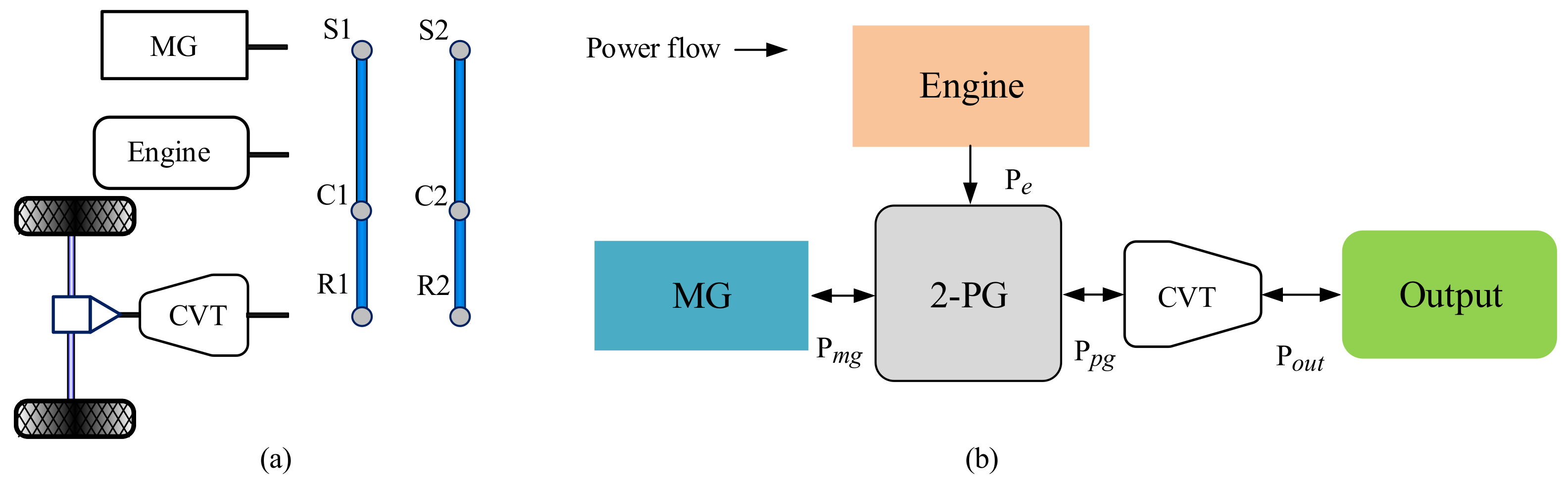
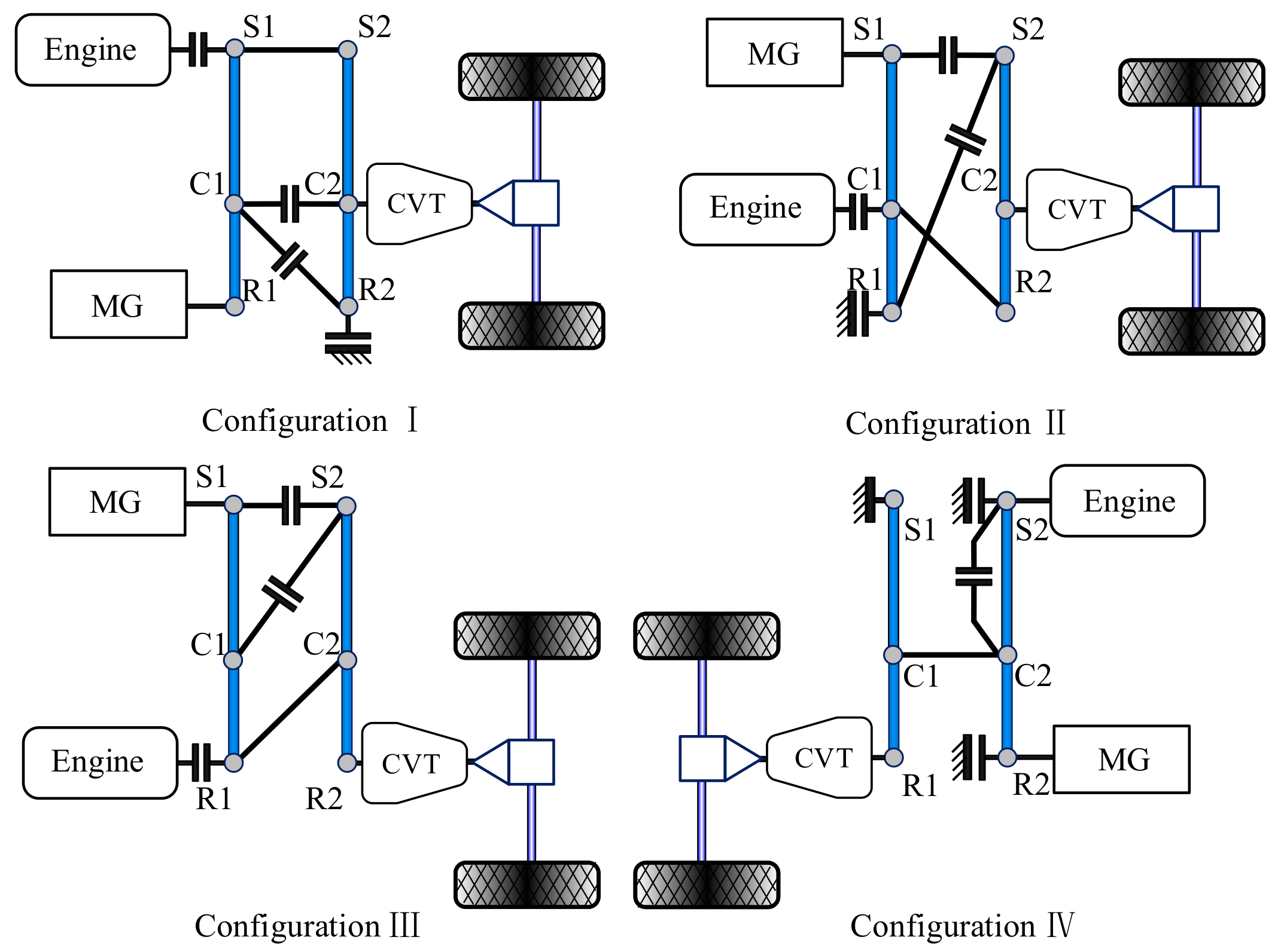
2.1. Basic Configuration Scheme

In recent years, a number of vehicles that adopt the single motor hybrid powertrain configuration scheme have been mass-produced and put into the market, such as Chery Arrizo 7e, as shown in Figure 1. The components of Arrizo 7e powertrain are mainly composed of PG, motor (MG), engine, output shaft, CVT, clutch (CL) and one-way clutch (OWC) [25]. The diagram of the powertrain configuration is shown in Figure 2. The configuration has three operating modes: speed coupling mode (CL1 and CL2 disengagement), torque coupling mode (CL1 engagement, CL2 disengagement) and engine-alone driving mode (CL1 disengagement, CL2 engagement). In this configuration, the MG adjusts the engine speed and torque in the speed coupling mode and torque coupling mode, respectively, and CVT adjusts the output speed and torque of the system. Therefore, the configuration possesses two ways of adjustment, which are the MG electric adjustment and the CVT mechanical adjustment.
To further improve the comprehensive operating performance of the above single motor hybrid powertrain configuration, the basic configuration scheme for the SMHPC-2PG is proposed by combining the advantages of dual PGs configuration in this paper, as shown in Figure 3. In the basic configuration scheme, the number of PG is increased to two on the premise that the number of main components (engine, MG, CVT) is the same as that of Arrizo 7e. Therefore, the basic configuration scheme not only retains the adjustment function of MG and CVT, but also possesses various combinations and connections by introducing two PGs, thus the space of topology design is expanded, and the improvement potential of the comprehensive operating performance for the single motor hybrid powertrain configuration is increased.
In the basic configuration scheme, the clutch locations are shown in Figure 4 [26], and the total number of locations nclutch_total is calculated by Equation (1).
n c l u t c h _ t o t a l = C 3 n 2 + 3 n
where n is the number of PGs.
It can be concluded that there are at most 21 clutch locations in this basic configuration scheme. By selecting different clutch locations and changing the ways of combination and connection between components and the PG nodes, the constraint relationship of the system can be changed, which generates different operating modes. The generation process of operating mode is shown in Figure 5. To avoid redundancy and infeasible topology; the following infeasible ways of combination and connection should be excluded in the generation process.
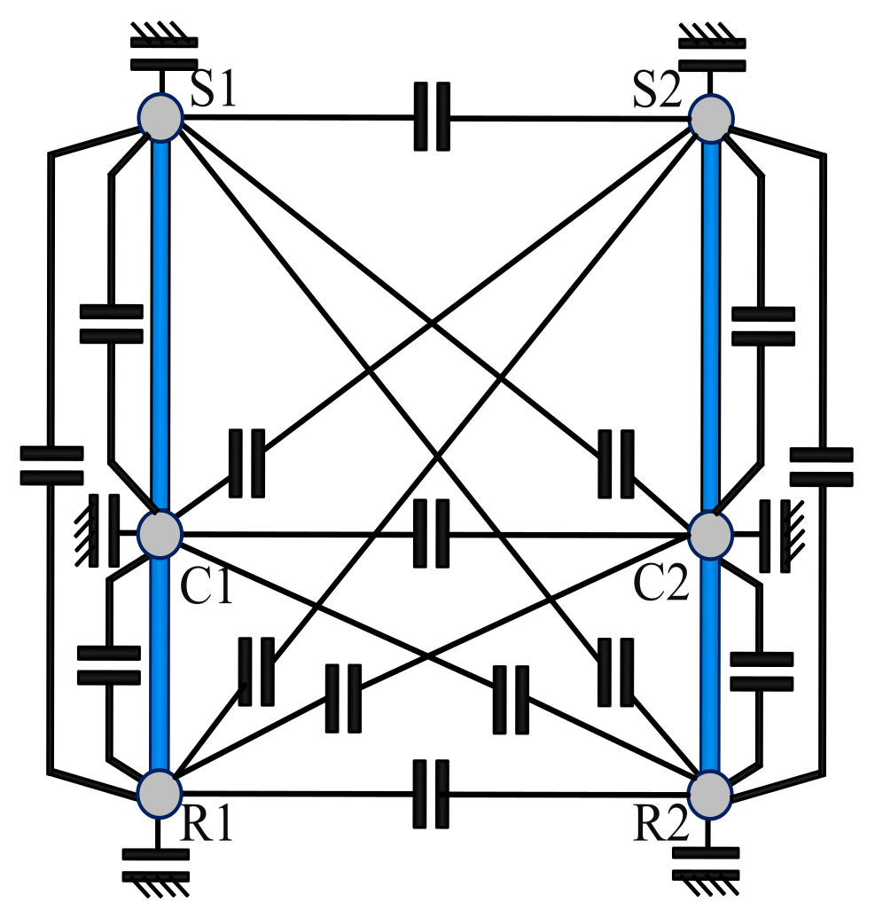
  • Any node of PG is connected to two or three nodes of the other PG at the same time.
  • Three nodes of PG are grounded at the same time.
  • Three nodes of PG have two or three interconnections at the same time.

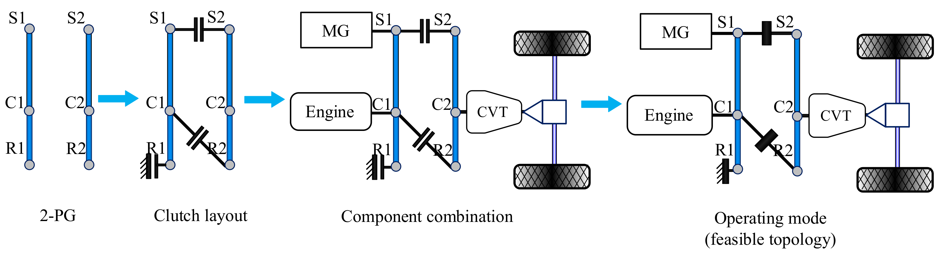
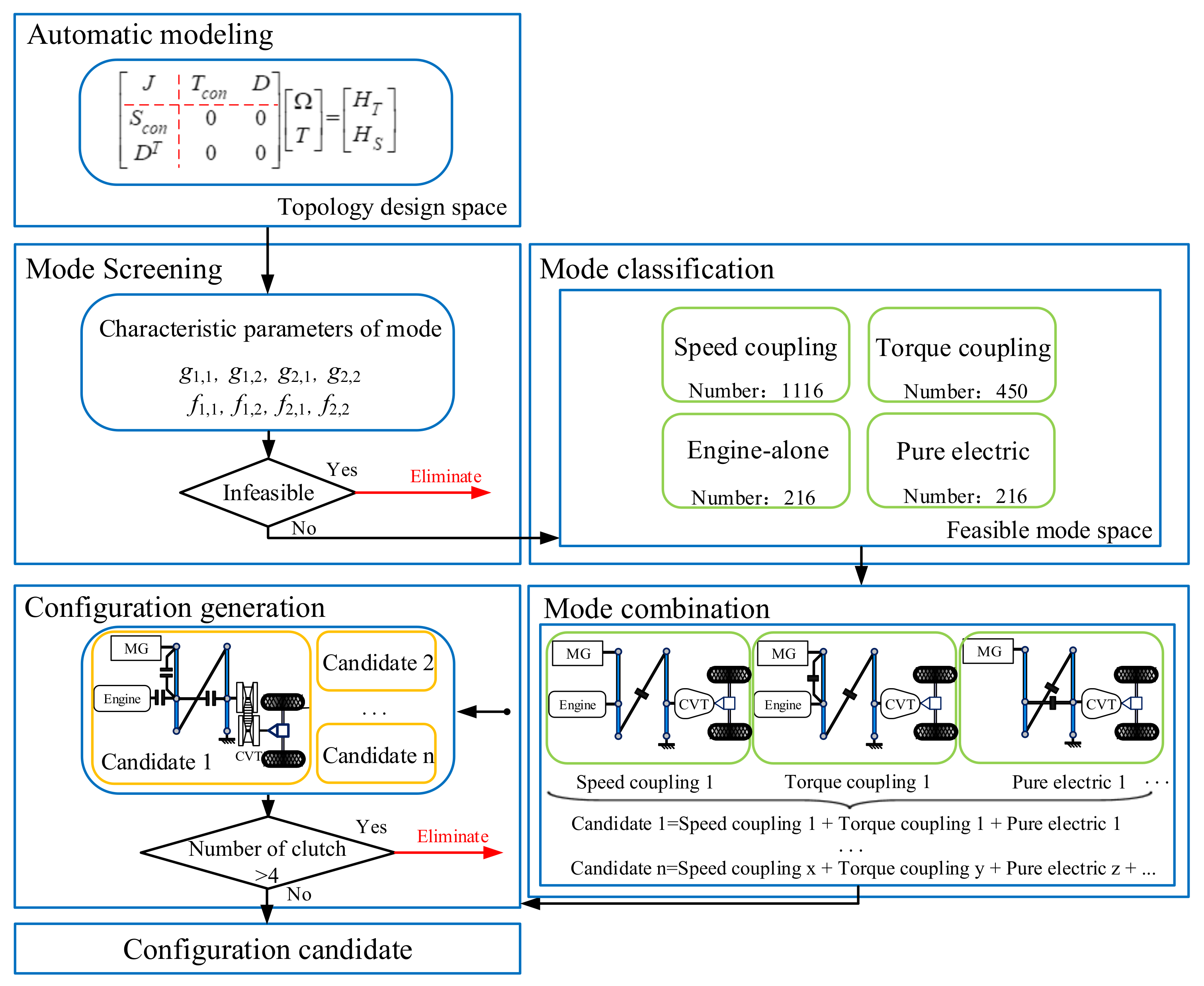
2.2. Topology Design Method

To systematically generate all feasible operating modes in the complex topology of the proposed basic configuration scheme, and rapidly classify and combine the operating modes to generate configuration candidates, a general topology design method that characterizes the constraint relationship between power resource components and PG nodes is proposed in this paper.

2.2.1. Automatic Modeling of Operating Mode

Because of the large number of operating modes in the basic configuration scheme, to explain the proposed topology design method more conveniently, this paper selects the operating mode shown in Figure 5 as an example to illustrate. According to the proposed topology design method, the dynamics relationship of this mode is shown in Equation (2). The fundamental matrix A is composed of rotational inertia matrix J, matrix D [27,28,29], torque constraint matrix Tcon and speed constraint matrix Scon.
Applsci 09 00707 i001
where I, ω, T are the rotational inertia, the speed, and the torque, respectively; the subscripts represent corresponding components and nodes. It should be noted that because the R1 node is grounded, TR1 represents the braking torque that locks the R1 node. F1 and F2 represent the internal force of PG1 and PG2, respectively, notice that they are intermediate variables for solving equation; Tpg, ωpg are output torque and speed of the PG, respectively; −Ri, Ri + Si, −Si are the note coefficients of the ring gear, carrier and sun gear of PGi, respectively. The value of note coefficients is related to the radius of the nodes [27].
J is a diagonal matrix of size 3n × 3n. In this paper, the first three diagonal elements in matrix J from top left to bottom right are the sum of the inertia of engine, output shaft, MG, and the inertia of the notes they connect, respectively. Therefore, the first three diagonal elements of matrix J in Equation (2) are Ie + IC1, Iout + IC2, and Img + IS1, respectively. The latter three diagonal elements are the inertia of the nodes which are not connected to the components. They are arranged in matrix J in the sequence of the ring gear, carrier, and sun gear from PG1 to PG2.
In the initial state, the torque constraint matrix Tcon is a negative unit matrix of size 3n × 3n. The diagonal elements of the matrix Tcon correspond to the diagonal elements of the matrix J one by one. When any two nodes of PG are connected, the extended intersection Tcon i, j of corresponding diagonal elements Tcon i, i, Tcon j, j (i < j) for the two nodes in the matrix Tcon is transformed from zero to one. The speed constraint matrix Scon is composed of connection constraint and locking constraint, because the carrier and sun gear of PG1 are connected with the ring gear and sun gear of PG2, respectively, and the ring gear of PG1 is grounded in this mode. Therefore, the first two rows of the matrix Scon are expressed as connection constraint of nodes. The third row of the matrix Scon is expressed as the locking constraints of the PG1 ring gear.
The size of matrix D is 3n × n. When the components are connected to the ring gear, carrier, and sun gear of PGi, respectively, the node coefficients −Ri, Ri + Si, −Si are filled at the corresponding positions in column i of matrix D, respectively. The nodes which are not connected to the components fill in their own node coefficients at the corresponding positions of matrix D. Matrix a is composed of matrix Ω and matrix T. The size of matrix Ω is 3n × 1, and the matrix element is angular acceleration. The size of matrix T is 4n × 1, and matrix elements are composed of torque and internal force F1 and F2. The dynamic equation of the system can be rewritten to Equation (3).
{ A a = H A = [ J D 1 D 2 0 ] , D 1 = [ T c o n D ] , D 2 = [ S c o n D T ] T   =   [ J T c o n D S c o n 0 0 D T 0 0 ] a = [ Ω T ] H = [ H T H S ]
The relationship both steady-state torque and speed for power resource components and PG nodes are calculated by Equation (4) and (5), respectively.
{ [ T c o n D ] T = 0 i = 1 3 n j = 1 3 n T c o n   i , j T j , 1 + D i , 1 T 3 n + 1 , 1 + D i , 2 T 3 n + 2 , 1 = 0
{ W = [ ω e ω p g ω m g ω R 1 ω R 2 ω S 2 ] T [ S c o n D T ] T W = 0 i = 1 3 j = 1 3 n S c o n   i , j W j , 1 = 0   i = 1 n j = 1 3 n D T i , j W j , 1 = 0
where matrix W is rotational speed matrix.
According to the proposed topology design method, by changing the arrangement of non-zero elements in the matrix Tcon, Scon and the number of rows in the matrix Scon, the complex and changeable constraint relationship between power resource components and PG nodes can be expressed, and the dynamic model of corresponding operating mode can be generated. Therefore, the proposed method has generality in expressing and generating dynamic models of operating modes.

2.2.2. Mode Screening and Classification

Equation (2) shows that if there is only one non-zero element in row i (i > 3) of matrix Tcon, the corresponding node of this row can be determined to be locked. Therefore, the row can be deleted in matrix Tcon, and the row of the corresponding node in matrix D can also be deleted. The transformation process is shown in Equation (6). When the node of row i is connected to the node of row j (i < j), the element of row j is added to row i, and row j is deleted in matrix Tcon and matrix D. The transformation process is shown in Equation (7).
{ T c o n   i ,   : = [   ] D   i ,   : = [   ]
{ T c o n   i ,   : = T c o n   i ,   : + T c o n   j ,   : T c o n   j ,   : = [   ] D   i ,   : = D   i ,   : + D   j ,   : D   j ,   : = [   ]
According to Equations (6) and (7), matrix Tcon is transformed into matrix Tcon*, and its size is (3nq) × 3n, q is the number of clutches that lock and connect PG nodes. Similarly, matrix D is transformed into matrix D*, and its size is (3nq) × n. According to [Tcon*, D*]·T = 0, the torque relationship of each component can be obtained as shown in Equation (8). The matrix Scon represents the speed relationship of the system. Solving [Scon, DT]T·W = 0 by applying Gauss elimination method, the speed relationship of each component can be obtained as shown in Equation (9).
{ T e = f 1 , 1 ( k 1 , k 2 ) T p g + f 1 , 2 ( k 1 , k 2 ) T m g T p g = f 2 , 1 ( k 1 , k 2 ) T e + f 2 , 2 ( k 1 , k 2 ) T m g
{ ω e = g 1 , 1 ( k 1 , k 2 ) ω p g + g 1 , 2 ( k 1 , k 2 ) ω m g ω p g = g 2 , 1 ( k 1 , k 2 ) ω e + g 2 , 2 ( k 1 , k 2 ) ω m g
where k is the radius ratio of the ring gear to sun gear; k i = R i / S i ; f 1 , 1 ,   f 1 , 2 , f 2 , 1 , f 2 , 2 are the torque coefficients; g 1 , 1 , g 1 , 2 , g 2 , 1 , g 2 , 2 are the speed coefficients.
The torque and speed coefficients are defined as mode characteristic parameters, and all operating modes can be classified according to mode characteristic parameters and criteria, as shown in Table 1.

2.2.3. Mode Combination and Configuration Generation

According to the above criteria, a total of 1998 feasible operating modes are screened out. And configuration candidates can be generated by combining the classified operating modes. This paper stipulates that all the configuration candidates must include speed coupling mode, torque coupling mode, and pure electric mode, so the MG can adjust engine speed/torque and drive vehicle, respectively. To reduce the control complexity of configuration, the number of clutches used for mode switching must not exceed four in all configuration candidates. The generation process of configuration candidate is shown in Figure 6.

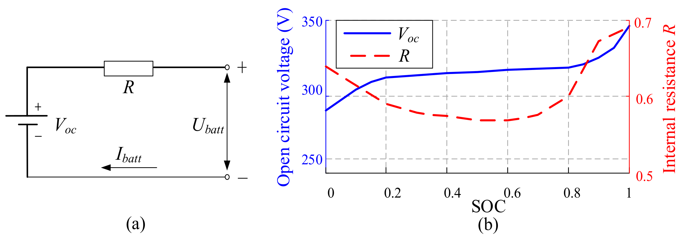
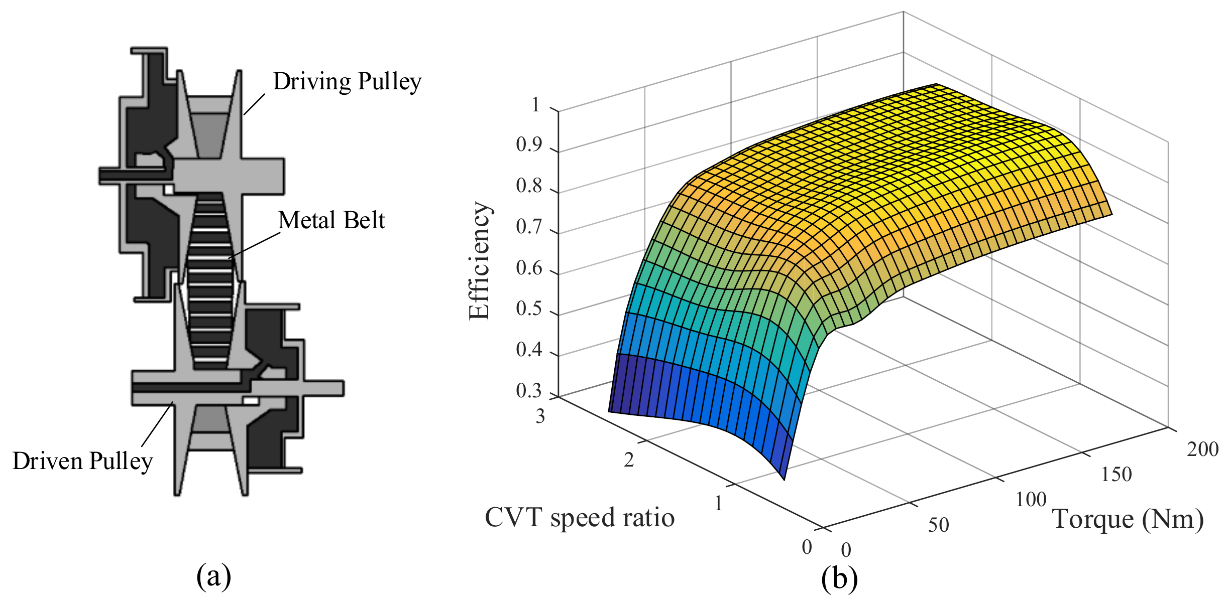
3. Parameter and Model

All configuration candidates adopt the same parameters as shown in Table 2. It is assumed that there is only a pure rolling state of the wheel, no sliding between the wheel and the ground. And the yaw stability of the vehicle is not considered. The driving force Fout, driving torque Tout and the speed of output shaft ωout for the vehicle are shown in Equations (10) and (11).
{ F o u t = m g f r cos a + 1 21.15 C D A v 2 + m g sin a + δ m d v d t T o u t = F o u t r T p g = T o u t η C V T i C V T i 0
{ ω o u t = v r ω p g = ω o u t i 0 i C V T
where m is the vehicle mass; v is the driving speed; a is the climbing slope; fr is the rolling resistance coefficient; CD is the aerodynamic drag coefficient; A is the front section; δ is the rotating mass coefficient; g is the gravity acceleration, the value is 9.8 m/s2; r is the radius of wheel; i0 is the gear ratio of final drive; iCVT is the speed ratio of CVT; ηCVT is the operating efficiency of CVT, its value is related to CVT input torque and CVT speed ratio by look-up table. The structure and efficiency model of CVT are shown in Figure 7.
In this paper, the internal resistance model is selected as the battery model [30]. As shown in Figure 8a. The battery power based on this model is calculated by Equation (12).
P b a t t = V o c I b a t t I b a t t 2 R
where Pbatt is battery power; Voc is open circuit voltage; Ibatt is current; R is internal resistance; Voc and R are related to SOC (state of charge), as shown in Figure 8b.
The current is obtained by solving Equation (13).
I b a t t = V o c V o c 2 4 R P b a t t 2 R
The SOC can be calculated by Equation (14).
S O C t = S O C 0 1 Q N 0 t I b a t t d t
where SOCt is the SOC at t time; SOC0 is the SOC at the initial time; QN is the capacity of battery; t is the time for battery charging and discharging.

4. Control Strategy and Configuration Optimization

In this paper, the global optimal control strategy is formulated by adopting the DP algorithm [31,32] and based on this control strategy, the optimal fuel economy and the optimal dynamic performance for all configuration candidates are simulated.

4.1. Control Strategy

The state variable and control variable of the control strategy for the optimal fuel economy and the optimal dynamic performance are shown in Table 3.
The cost function of the optimal fuel economy control strategy Jfuel is shown in Equation (15).
J f u e l = k = 0 N 1 ( f u e l k + β Δ M o d e k + γ | S O C 0 S O C k | )
where fuelk is the fuel consumption at step k; SOCk is the SOC at step k; β, γ are the weight factors of the mode penalty function and the SOC penalty function, respectively. The cost function Jfuel consists of fuel consumption, mode penalty function, and SOC penalty function; the latter two penalty functions are set to avoid frequent mode switching and maintain the balance of initial and terminal SOC, respectively.
In this paper, 0–120 km/h acceleration time is selected as the evaluation index of dynamic performance [30]. In the acceleration process, it is assumed that SOC is sufficient and battery power always meets the power requirements of the MG. The acceleration time Jacc as the cost function of the optimal dynamic performance control strategy is shown in Equation (16).
{ J a c c = k = 1 120 Δ v a k + β Δ M o d e k a k = d v dt = F k _ max ( m g f r cos a + 1 21.15 C D A v 2 + m g sin a ) δ m
where Δv is the speed sample selected as 1 km/h; ak is the acceleration at speed step k; Fk_max is the maximum driving force at speed step k.

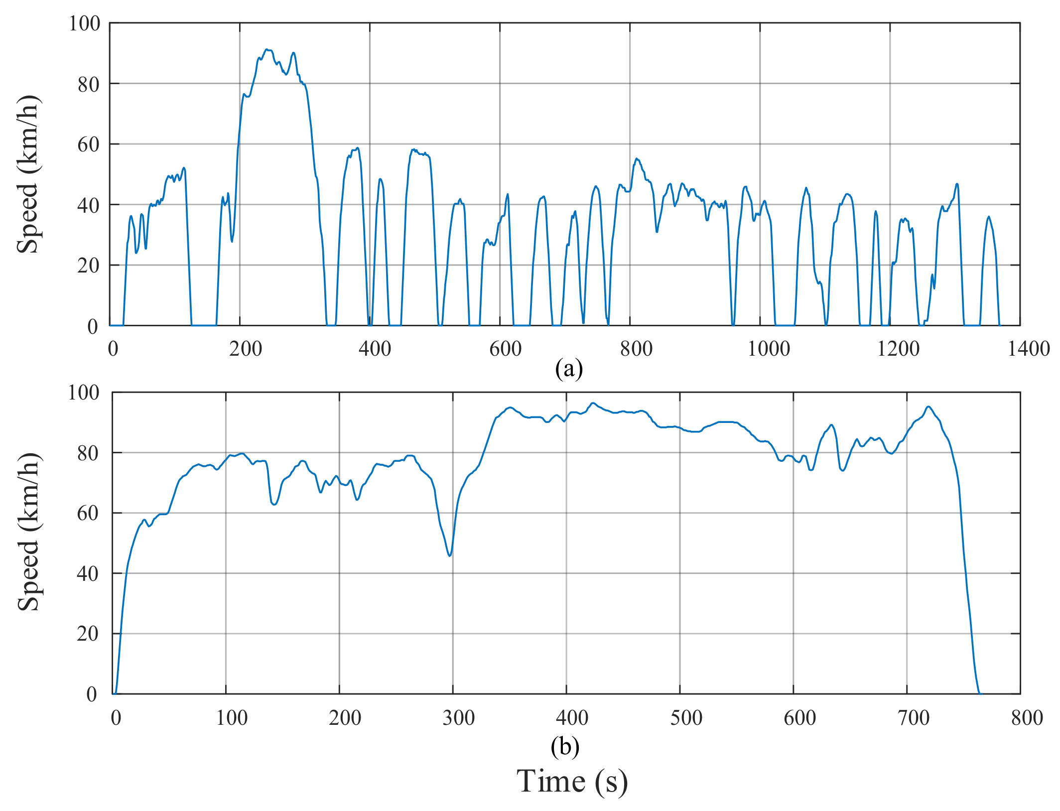
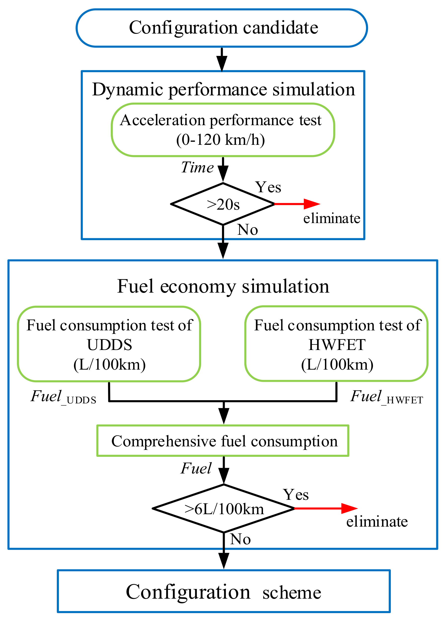
4.2. Performance Simulation

The optimal fuel economy and dynamic performance for all configuration candidates are simulated by applying the control strategy formulated in Section 4.1. First, the dynamic performance of all configuration candidates is simulated, and the configuration with an acceleration time of 0–120 km/h of more than 20 s is eliminated. Second, the fuel economy simulation for all configurations with acceleration time less than 20 s is carried out. According to Environmental Protection Agency (EPA) standard [33], the urban road cycle (UDDS) and highway cycle (HWFET) are selected as fuel economy test cycles. The test cycles are shown in Figure 9. By weighted calculation for the fuel consumption of test cycles, the comprehensive fuel consumption Fuel can be obtained, as shown in Equation (17). Last, the configurations with acceleration time less than 20 s and the comprehensive fuel consumption less than 6 L/100 km are screened out. The process of performance simulation and configuration screening is shown in Figure 10.
F u e l = 1 0.55 F u e l _ UDDS + 0.45 F u e l _ HWFET
where Fuel_UDDS and Fuel_HWFET are the fuel consumption of the UDDS and HWFET, respectively.

5. Results and Analysis

By simulating the optimal dynamic performance and the optimal fuel economy for the configuration candidates, 196 configurations that satisfy the screening conditions are obtained. To further obtain the configuration with excellent comprehensive performance, Arrizo 7e is selected as the reference configuration to optimize all configurations that satisfy the screening conditions. Finally, the four Pareto optimal configurations (configuration I–IV) with better fuel economy and dynamic performance than reference configuration are obtained, as shown in Figure 11. In Pareto optimal configurations, configuration IV has the best dynamic performance with an acceleration time of 10.0642 s, and configuration I has the best fuel economy of 3.7141 L/100 km. Configuration II at the corner of Pareto front possesses the most balanced performance, which means that it has the best comprehensive performance. The acceleration time of 0–120 km/h and the fuel economy for configuration II are 10.2124 s and 3.9251 L/100 km, respectively. Four Pareto optimal configurations are shown in Figure 12, and their acceleration time, fuel economy, and operating mode are shown in Table 4.
To further explore the characteristics of energy consumption for the optimal configuration in the proposed scheme, the configuration II with the best comprehensive performance and the reference configuration Arrizo 7e are selected for the comparative analysis of energy consumption. The performance of the reference configuration is also simulated by applying the global optimal control strategy based on DP. Compared with the reference configuration, the fuel economy and dynamic performance of configuration II are improved by 11.26% and 25.40%, respectively. Under the urban road cycle and highway cycle, the distributions of working points for power resource components and SOC curves in configuration II are shown in Figure 13 and Figure 14. Most of the engine working points of configuration II are close to the optimal operating line (OOL), which indicates that the adjustment approach combining MG and CVT adopted in configuration II can adjust the engine speed and torque excellently, and keep the engine operate in high efficiency continuously.
Table 5 presents the proportion of high-efficiency region of engine working points in the two configurations (In this paper, the region with fuel consumption rate less than 270 g/kW·h is defined as the high-efficiency region). Table 6 shows the average efficiency of MG in the two configurations under different test cycles. From Table 5, it can be seen that the engine operating efficiency of configuration II has been significantly improved in the urban road cycle, and the proportion of high-efficiency region has been increased by 7.75% compared with the reference configuration. In the highway cycle, due to the high operating efficiency of engine, the potential to further improve engine efficiency is limited. Therefore, the proportion of high-efficiency region of configuration II is only 0.93% higher than the reference configuration. As shown in Table 6, in the urban road cycle and highway cycle, the MG average efficiency of configuration II increases by 3.38% and 5.47%, respectively compared with the reference configuration. Combined with Table 5 and Table 6, the overall operating efficiency of power resource components in configuration II has been effectively improved, which confirms that the SMHPC-2PG possesses excellent energy-saving performance.
Figure 15 shows the energy loss of the configuration II and the reference configuration in different test cycles. In the urban road cycle, the improvement of fuel economy for configuration II is mainly due to the raising of operating efficiency of power resource components, as shown in Figure 15a. Compared with the reference configuration, the energy loss of engine and MG in configuration II decreased by 10.6% and 26.5%, respectively. In the highway cycle, because of the high efficiency of the engine in configuration II and reference configuration, the reduction of energy loss for the transmission system and MG becomes the main factor to improve the fuel economy of configuration II. As shown in Figure 15b, compared with the reference configuration, the energy loss of the transmission system and MG in configuration II are reduced by 1140 kJ and 930 kJ, respectively.

6. Conclusions

To further improve the comprehensive operating performance of the single motor hybrid electric vehicle, the SMHPC-2PG design was proposed in this paper. By adopting a topology design method that characterizes the constraint relationship between power resource components and PG nodes, all feasible configuration candidates based on the basic configuration scheme were systematically explored, and dynamic models of configuration candidates were automatically generated. The optimal fuel economy and the optimal dynamic performance for configuration candidates were simulated based on the global optimal control strategy. Finally, the SMHPC-2PG with excellent comprehensive performance was obtained by screening. The following two points should be noted.
  • The main purpose of this paper was to provide a new design idea and scheme for the single motor hybrid powertrain configuration.
  • Compared with the reference configuration, four Pareto optimal configurations obtained by screening and optimization have obvious advantages in fuel economy and dynamic performance.

Author Contributions

J.H. wrote the first draft of the manuscript, proposed the topology design method. B.M. designed the process of performance simulation and configuration screening, completed the optimization of dynamic programming and dealt with the simulation data. H.P. and X.J. provided insights and additional ideas on presentation. All of the authors revised and approved the manuscript.

Funding

This research received no external funding.

Acknowledgments

This work was supported by the National Key Research and Development Program of China (No. 2016YFB0101402) and the Fundamental Research Funds for the Central Universities (No. 106112016CDJXZ338825). These projects offered all the costs of this series researches. The authors appreciate for their supports on these researches.

Conflicts of Interest

The authors declare no conflict of interest.

References

  1. Zheng, C.; Hengjie, H.; Yitao, W.; Renxin, X.; Jiangwei, S.; Yonggang, L. Energy management for a power-split plug-in hybrid electric vehicle based on reinforcement learning. Appl. Sci. 2018, 8, 2494. [Google Scholar]
  2. He, H.; Guo, X. Multi-objective optimization research on the start condition for a parallel hybrid electric vehicle. Appl. Energy 2018, 227, 294–303. [Google Scholar] [CrossRef]
  3. Insu, C.; Jongwon, B.; Junha, P.; Jinwook, L. Experimental evaluation and prediction algorithm suggestion for determining SOC of lithium polymer battery in a parallel hybrid electric vehicle. Appl. Sci. 2018, 8, 1641. [Google Scholar]
  4. Xiao, R.; Liu, B.; Shen, J.; Guo, N.; Yan, W.; Chen, Z. Comparisons of energy management methods for a parallel plug-in hybrid electric vehicle between the convex optimization and dynamic programming. Appl. Sci. 2018, 8, 218. [Google Scholar] [CrossRef]
  5. Qin, Z.; Luo, Y.; Zhuang, W.; Pan, Z.; Li, K.; Peng, H. Simultaneous optimization of topology, control and size for multi-mode hybrid tracked vehicle. Appl. Energy 2018, 212, 1627–1641. [Google Scholar] [CrossRef]
  6. Vinot, E.; Trigui, R.; Cheng, Y.; Bouscayrol, A.; Espanet, C. Optimal management and comparison of SP-HEV vehicles using the dynamic programming method. In Proceedings of the Vehicle Power and Propulsion Conference IEEE, Belfort, France, 14–17 December 2017; pp. 944–949. [Google Scholar]
  7. Yue, T.; Lior, N. Thermodynamic analysis of hybrid Rankine cycles using multiple heat sources of different temperatures. Appl. Energy 2018, 222, 564–583. [Google Scholar] [CrossRef]
  8. Yue, H.; Weimin, L. Energy management strategy for a hybrid electric vehicle based on deep reinforcement learning. Appl. Sci. 2018, 8, 187. [Google Scholar]
  9. Zhang, X.; Li, C.T.; Peng, H. Prius+ and Volt−: Configuration analysis of power-split hybrid vehicles with a single planetary gear. IEEE Trans. Veh. Technol. 2012, 61, 857–865. [Google Scholar]
  10. Zhuang, W.; Zhang, X.; Li, D.; Wang, L. Mode shift map design and integrated energy management control of a multi-mode hybrid electric vehicle. Appl. Energy 2017, 204, 476–88. [Google Scholar] [CrossRef]
  11. Barhoumi, T.; Kum, D. Automatic enumeration of feasible kinematic diagrams for power-split hybrid configurations with a single planetary gear. J. Mech. Design 2017, 139, 083301. [Google Scholar] [CrossRef]
  12. Zhang, X.; Li, S.E.; Peng, H.; Sun, J. Design of multimode power-split hybrid vehicles—A case study on the Voltec powertrain system. IEEE Trans. Veh. Technol. 2016, 65, 4790–4801. [Google Scholar] [CrossRef]
  13. Kim, H.; Kum, D. Comprehensive design methodology of input- and output-split hybrid electric vehicles: In search of optimal configuration. IEEE/ASME Trans. Mechatron. 2016, 21, 2912–2923. [Google Scholar] [CrossRef]
  14. Zhang, X.; Peng, H.; Sun, J. A near-optimal power management strategy for rapid component sizing of power split hybrid vehicles with multiple operating modes. IEEE Trans. Control Syst. Technol. 2015, 23, 609–618. [Google Scholar] [CrossRef]
  15. Zhang, X.; Li, S.E.; Peng, H.; Sun, J. Efficient exhaustive search of power-split hybrid powertrains with multiple planetary gears and clutches. J. Dyn. Syst. Meas. Control 2015, 137, 121006. [Google Scholar] [CrossRef]
  16. Zhuang, W.; Zhang, X.; Ding, Y.; Wang, L.; Hu, X. Comparison of multi-mode hybrid powertrains with multiple planetary gears. Appl. Energy 2016, 178, 624–632. [Google Scholar] [CrossRef]
  17. Bayrak, A.E.; Kang, N.; Papalambros, P.Y. Decomposition-based design optimization of hybrid electric powertrain architectures: Simultaneous configuration and sizing design. J. Mech. Des. 2016, 138, 071405. [Google Scholar] [CrossRef]
  18. Yang, Y.; Hu, X.; Pei, H.; Peng, Z. Comparison of power-split and parallel hybrid powertrain architectures with a single electric machine: Dynamic programming approach. Appl. Energy 2016, 168, 683–690. [Google Scholar] [CrossRef]
  19. Wang, W.; Song, R.; Guo, M.; Liu, S. Analysis on compound-split configuration of power-split hybrid electric vehicle. Mech. Mach. Theory 2014, 78, 272–288. [Google Scholar] [CrossRef]
  20. Sundström, O.; Guzzella, L.; Soltic, P. Optimal hybridization in two parallel hybrid electric vehicles using dynamic programming. IFAC Proc. Vol. 2008, 41, 4642–4647. [Google Scholar] [CrossRef]
  21. Debal, P.; Faid, S.; Tricoche, L.; Bervoets, S. CVT-based full hybrid powertrain offering high efficiency at lower cost. In Proceedings of the SAE World Congress, Detroit, MI, USA, 13–15 April 2010. [Google Scholar]
  22. Sun, J.K.; Kim, K.S.; Kum, D. Feasibility assessment and design optimization of a clutchless multimode parallel hybrid electric powertrain. IEEE/ASME Trans. Mechatron. 2016, 21, 774–786. [Google Scholar]
  23. Kim, N.; Kwon, J.; Rousseau, A. Comparison of powertrain configuration options for plug-in hevs from a fuel economy perspective. SAE Tech. Paper 2012. [Google Scholar] [CrossRef]
  24. Lee, S.; Lee, B.; McDonald, J.; Sanchez, L.J.; Nam, E. Modeling and validation of power-split and P2 parallel hybrid electric vehicles No. 2013-01-1470. SAE Tech Paper 2013. [Google Scholar] [CrossRef]
  25. Liu, G.; Zhou, M.Z.; Wang, L.L.; Wang, H. A radar-based door open warning technology for vehicle active safety. In Proceedings of the International Conference on Information System & Artificial Intelligence, Tianjin, China, 14–16 July 2017. [Google Scholar]
  26. Zhang, X.; Peng, H.; Sun, J. Not just for fuel economy: A systematic design and exhaustive search for hybrid multimode light trucks. IFAC PapersOnLine 2015, 48, 1–7. [Google Scholar] [CrossRef]
  27. Liu, J.; Peng, H. Modeling and control of a power-split hybrid vehicle. IEEE Trans. Control Syst. Technol. 2008, 16, 1242–1251. [Google Scholar]
  28. Dagci, O.H.; Peng, H.; Grizzle, J.W. Hybrid electric powertrain design methodology with planetary gear sets for performance and fuel economy. IEEE Access 2018, 99, 1. [Google Scholar] [CrossRef]
  29. Zhuang, W.; Zhang, X.; Peng, H.; Wang, L. Rapid configuration design of multiple-planetary-gear power-split hybrid powertrain via mode combination. IEEE/ASME Trans. Mechatron. 2016, 21, 2924–2934. [Google Scholar] [CrossRef]
  30. Zhou, X.; Qin, D.; Hu, J. Multi-objective optimization design and performance evaluation for plug-in hybrid electric vehicle powertrains. Appl. Energy 2017, 208, 1608–1625. [Google Scholar] [CrossRef]
  31. Bellman, R. Dynamic programming. Science 1966, 153, 34–7. [Google Scholar] [CrossRef] [PubMed]
  32. Peng, J.; He, H.; Xiong, R. Rule based energy management strategy for a series-parallel plug-in hybrid electric bus optimized by dynamic programming. Appl. Energy 2016, 185, 1633–1643. [Google Scholar] [CrossRef]
  33. Kang, M.; Kim, H.; Kum, D. Systematic configuration selection methodology of power-split hybrid electric vehicles with a single planetary gear. In ASME 2014 Dynamic Systems and Control Conference; American Society of Mechanical Engineers: New York, NY, USA, 2014; p. V001T15A001. [Google Scholar]
Figure 1. Arrizo 7e.
Applsci 09 00707 g001
Figure 2. Arrizo 7e powertrain configuration.
Applsci 09 00707 g002
Figure 3. Basic configuration scheme. (a) Framework; (b) Schematic diagram.
Applsci 09 00707 g003
Figure 4. All clutch locations.
Applsci 09 00707 g004
Figure 5. The generation process of the operating mode.
Applsci 09 00707 g005
Figure 6. The generation process of configuration candidate.
Applsci 09 00707 g006
Figure 7. Continuously variable transmission (CVT) structure and efficiency model. (a) Structure; (b) Efficiency model.
Applsci 09 00707 g007
Figure 8. Battery model. (a) Internal resistance model; (b) Open circuit voltage and internal resistance.
Applsci 09 00707 g008
Figure 9. Test cycle. (a) Urban road cycle (UDDS); (b) Highway cycle (HWFET).
Applsci 09 00707 g009
Figure 10. The process of performance simulation and configuration screening.
Applsci 09 00707 g010
Figure 11. Results of configuration optimization.
Applsci 09 00707 g011
Figure 12. Pareto optimal configuration.
Applsci 09 00707 g012
Figure 13. Distribution of components working points in configuration II. (a) UDDS; (b) HWFET.
Applsci 09 00707 g013
Figure 14. SOC (state of charge) curves of configuration II. (a) UDDS; (b) HWFET.
Applsci 09 00707 g014
Figure 15. Comparison of energy loss. (a) UDDS; (b) HWFET.
Applsci 09 00707 g015
Table 1. Mode classification and criteria.
Mode TypeSwitching Criteria
Speed coupling modef21,1 + f 21,2 ≠ 0, f 22,1 + f 22,2 ≠ 0,
g1,1g1,2 ≠ 0, g2,1g2,2≠0.
Torque coupling modef1,1f1,2 ≠ 0, f2,1f2,2 ≠ 0,
g21,1 + g21,2 ≠ 0, g22,1 + g22,2 ≠ 0.
Pure electric modeTe = 0, ωe = 0, f2,2 = -f1,2/f1,1 ≠ 0,
g2,2 = -g1,2/ g1,1 ≠ 0.
Engine-alone driving modeTmg = 0, ωmg = 0, f1,1= 1/f2,1 ≠ 0,
g1,1 = 1/g2,1 ≠ 0.
Table 2. Basic parameters of the vehicle.
ComponentParameterValue
VehicleMass (kg)1600
Aerodynamic drag factor0.301
Rolling resistance factor0.012
Wheel radius (m)0.307
EngineMaximum power (kW)93
Maximum torque (Nm)138
Range of speed (r/min)800~5600
MGMaximum torque (Nm)271
Maximum speed (r/min)10000
BatteryCapacity (Ah)6.5
Nominal voltage (V)352
Transmission systemRange of CVT speed ratio
Final drive gear ratio
0.442~2.432
3.95
R1:S1(k1), R2:S2(k2)2.6, 2.63
Table 3. State variable and control variable.
Simulation ProjectState VariableControl Variable
Fuel economySOCωe Tmg Mode iCVT
Dynamic performanceωeωmg Tmg Mode iCVT
Where ωe is the engine speed; ωmg, Tmg are the speed and torque of MG, respectively; Mode is the operating mode.
Table 4. Performance and operating mode of Pareto optimal configuration.
ConfigurationFuel Economy (L/100 km)Acceleration Capacity (s)Operating Mode
I3.714112.34121-spd, 2-trq, 1-EV
II3.925110.21241-spd, 2-trq, 1-EV
III4.035010.13341-spd, 1-trq, 1-EV
IV4.162910.06421-spd, 1-trq, 1-EV, 1-eng
Arrizo 7e4.423113.68951-spd, 1-trq, 1-eng
Where spd, trq, EV, and eng represent speed coupling mode, torque coupling mode, pure electric mode, and engine-alone driving mode, respectively.
Table 5. Proportion of high-efficiency region of engine working points.
UDDSHWFET
Configuration II61.20%79.05%
Reference configuration53.45%78.12%
Table 6. Average efficiency of MG.
UDDSHWFET
Configuration II78.61%78.85%
Reference configuration75.23%73.38%

