Article

CT Conversion Workflow for Intraoperative Usage of Bony Models: From DICOM Data to 3D Printed Models

1
Department of Industrial Engineering—DIN, University of Bologna, Viale del Risorgimento 2, 40100 Bologna, Italy
2
IRCCS Istituto Ortopedico Rizzoli—IOR, Via Pupilli 1, 40100 Bologna, Italy
*
Author to whom correspondence should be addressed.
Appl. Sci. 2019, 9(4), 708; https://doi.org/10.3390/app9040708
Submission received: 11 January 2019 / Revised: 13 February 2019 / Accepted: 17 February 2019 / Published: 18 February 2019
(This article belongs to the Section Applied Biosciences and Bioengineering)

Abstract

:
This paper presents the application of a low-cost 3D printing technology in pre-operative planning and intra-operative decision-making. Starting from Computed Tomography (CT) scans, we were able to reconstruct a 3D model of the area of interest with a very simple and rapid workflow, using open-source software and an entry level 3D printer. The use of High Temperature Poly-Lactic Acid (HTPLA) by ProtoPasta allowed fabricating sterilizable models, which could be used within the surgical field. We believe that our method is an appealing alternative to high-end commercial products, being superior for cost and speed of production. It could be advantageous especially for small and less affluent hospitals that could produce customized sterilizable tools with little investment and high versatility.

1. Introduction

Computed Tomography (CT) and Magnetic Resonance Imaging (MRI) are currently considered the gold standard imaging modalities to investigate the musculoskeletal system, providing three-dimensional (3D) information about the comprehensive anatomy of the examined structures. Whereas MRI is an accurate, radiation-free imaging modality for the investigation of soft tissues, CT is preferred for the study of the bony structures. In fact, it provides extensive and detailed information for pre-operative planning of complex fractures, deformities, bone tumors, and joint reconstruction. CT is less expensive, and can be more easily available, for example in emergency clinics. It takes less time for a complete scan and it is less sensitive to patient movement; these latter aspects, along with the use of very low dose of radiation, are helpful in small children, when MRI requires general anesthesia during the procedure, to avoid excessive movement. In the latest years, the escalation of additive manufacturing and augmented reality technologies has spread new perspectives in the use of CT. The 3D medical modeling, along with the Augmented Reality Training, is revolutionizing surgical training [1], providing a more accessible, less expensive, even more realistic, experience for surgeons, rather than the traditional training on cadavers. The 3D medical modeling can be useful for surgical robot operations where the doctor does not have direct contact with the surgical area. In this situation, a 3D physical model of the body internal structure can help to better visualize the instrument movements. On the patient side, 3D printings of anatomical models increase the transparency of the surgery and enhance the informed consent. With regard to this aspect, the patient has the opportunity to better understand the extent of his pathology, as well as the treatment proposed by the surgeon. A realistic 3D-printed model that reflects the relationship between a lesion and normal structures may be useful in the pre-operative planning for determining the safest surgical strategy, designing patient-specific surgical instruments [2,3] or custom implants that would otherwise unavailable or prohibitive in terms of cost. Finally, the combination of 3D printing technology and biotechnology, using biomaterials, cells, and growth factors, offers the opportunity to fabricate biomedical parts and scaffolds that maximally imitate natural tissue and organ characteristics, starting a new era in regenerative and transplantation medicine, in particular in bone, joint, and ligament reconstruction. Despite the obvious enthusiasm for these new technologies, important challenges must be overcome, to maximize the potential uses of 3D printing in clinical and surgical practice. To date, most of the software used in bio medical 3D printing require expensive and professional 3D printers, thus limiting the use of this technology only in highly specialized centers. In some situations, surgeons require sterilizable models within the surgical field (i.e., custom bone cutting guides), but 3D printed models made from sterilizable materials are very expensive. Finally, the entire process, from medical imaging data to the 3D printed anatomical model is generally time consuming, thus unsuitable in some clinical situations (for example in emergency). In this report, we describe our in-house production process of 3D printed, very low-cost, sterilizable, pediatric bone models. We aim to highlight the opportunity, especially for smaller centers and hospitals with limited resources, to create accurate sterilizable skeletal models and customized tools, which are suitable for clinical and surgical purposes.

2. Materials and Methods

The present study is a preliminary report of an ongoing research, investigating the feasibility and implementation of an “in-house” 3D printing service for clinical and surgical practice in pediatric orthopedics and traumatology. Ethical Approval was obtained for the present study. The proposed method is summarized in the workflow in Figure 1.

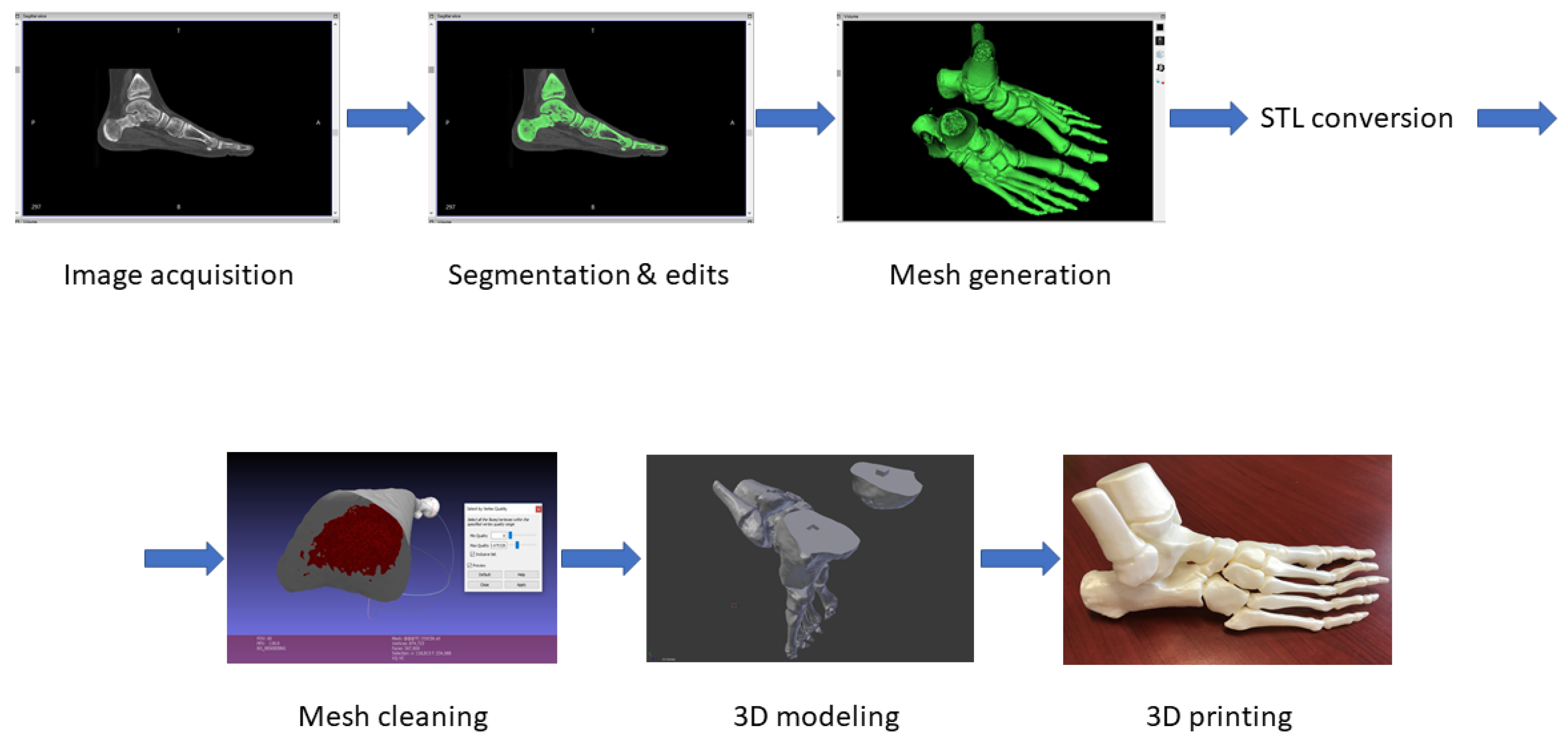
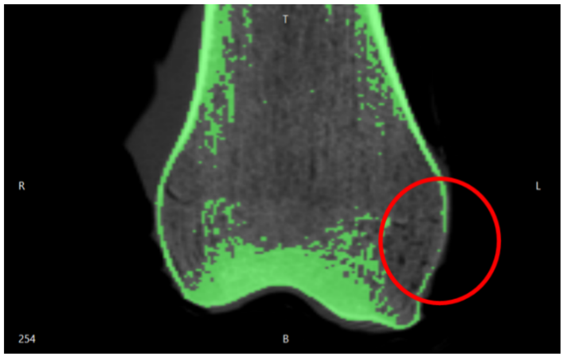
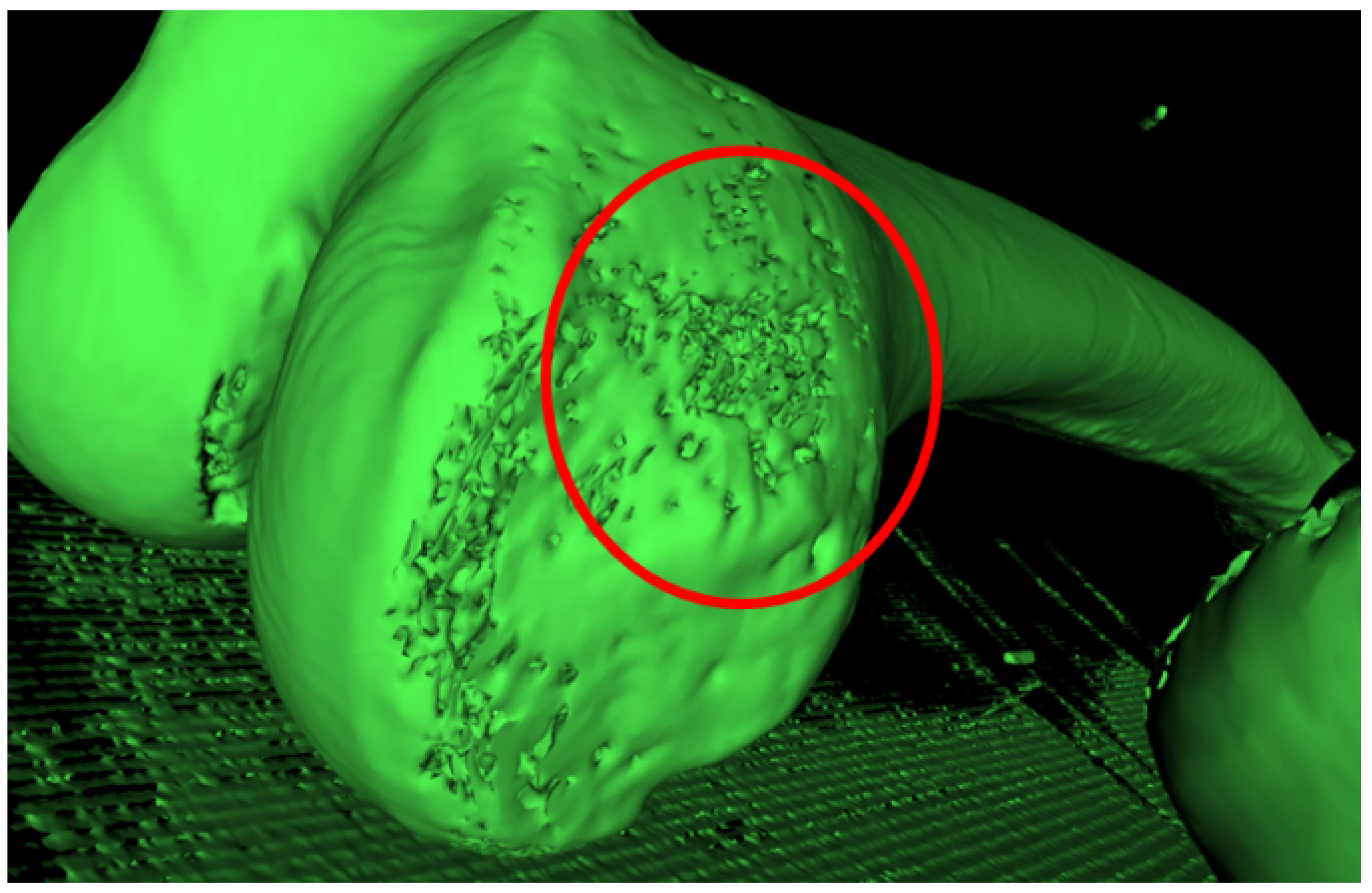
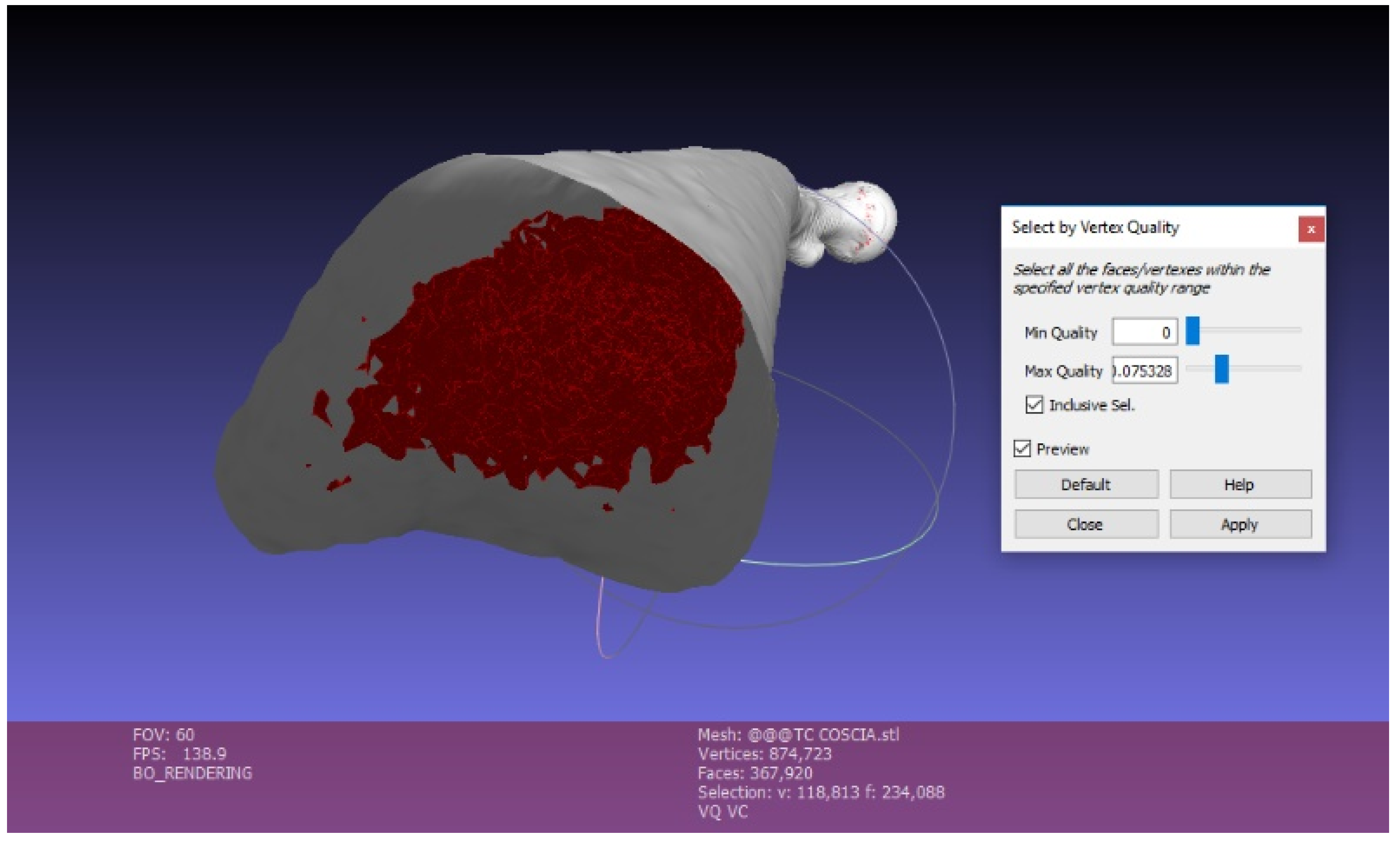
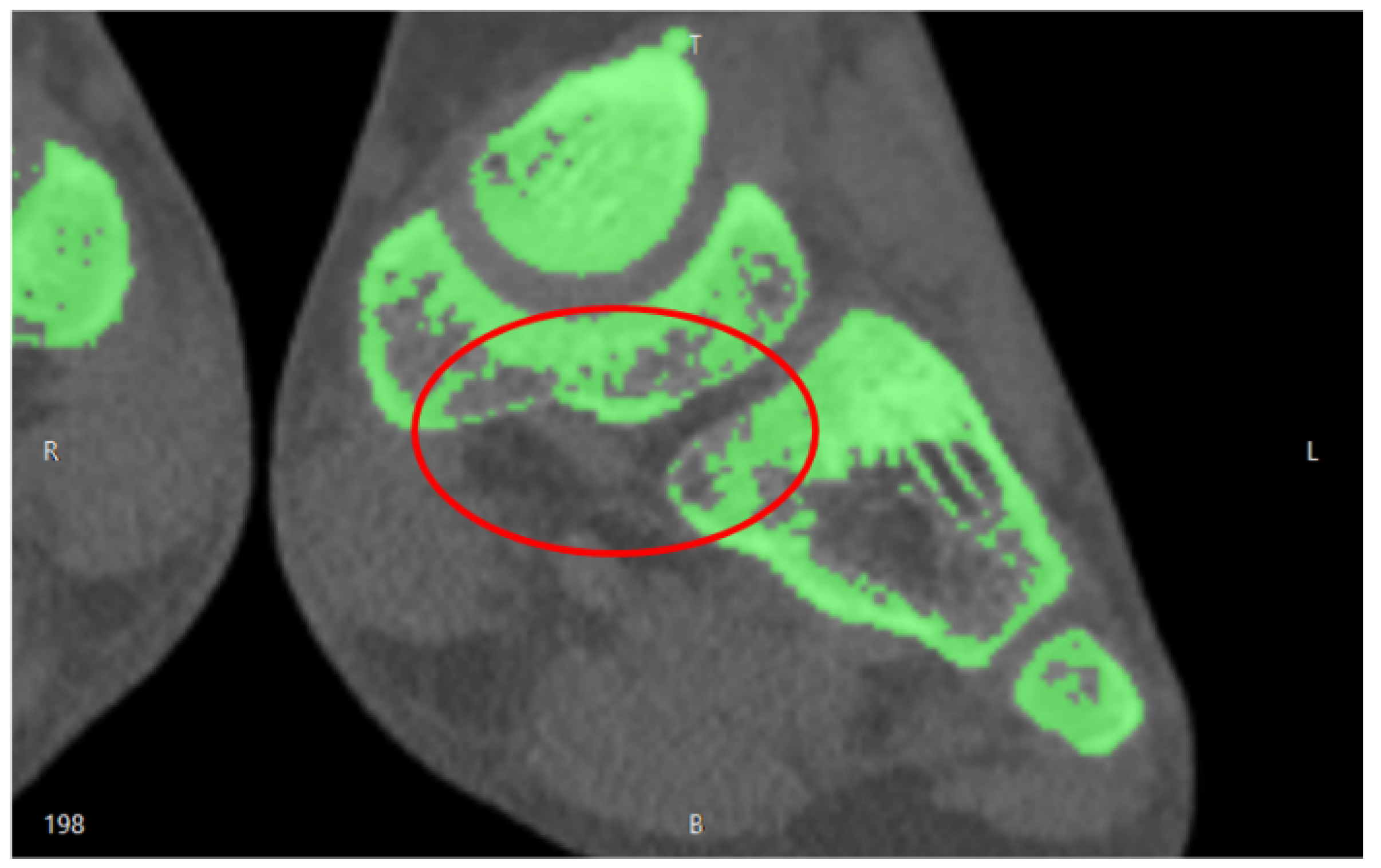
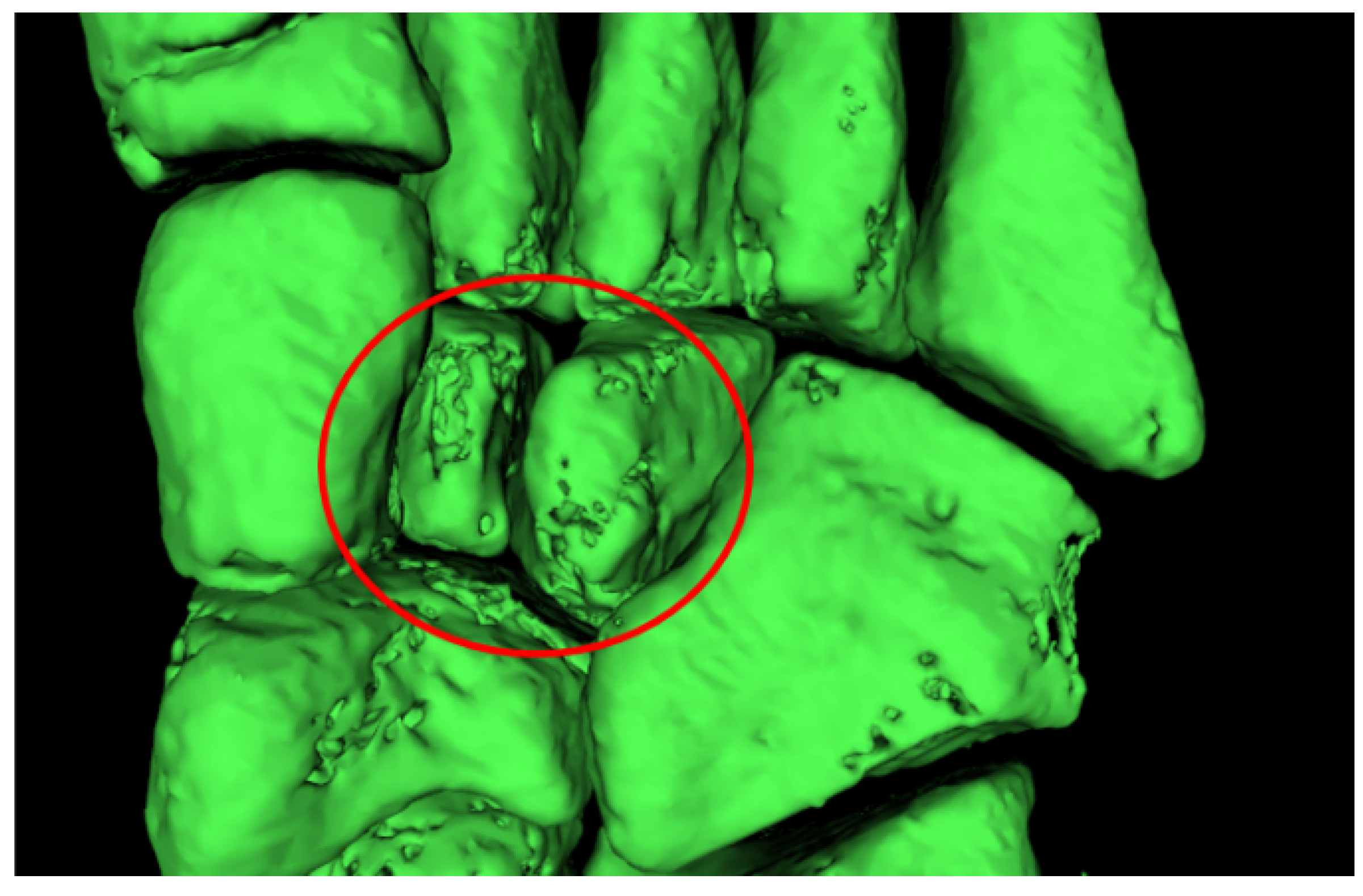
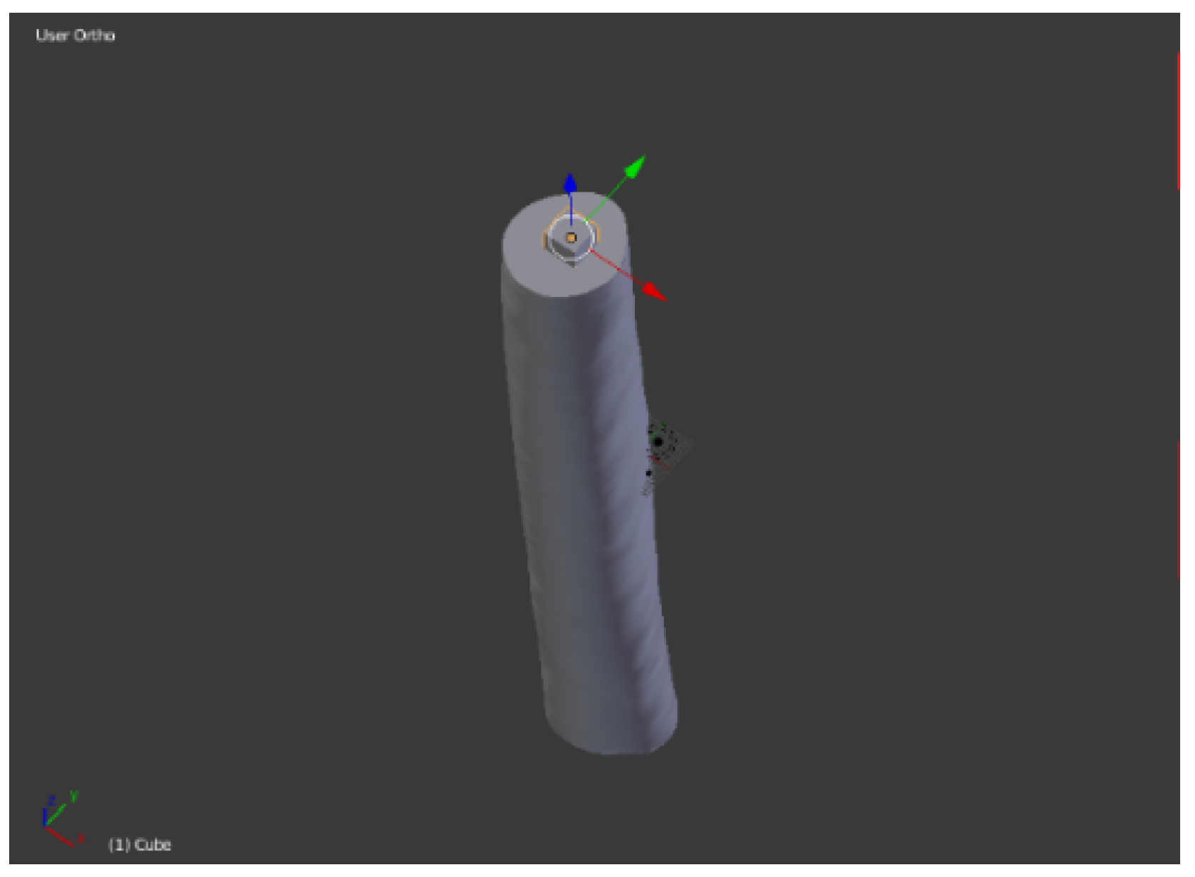
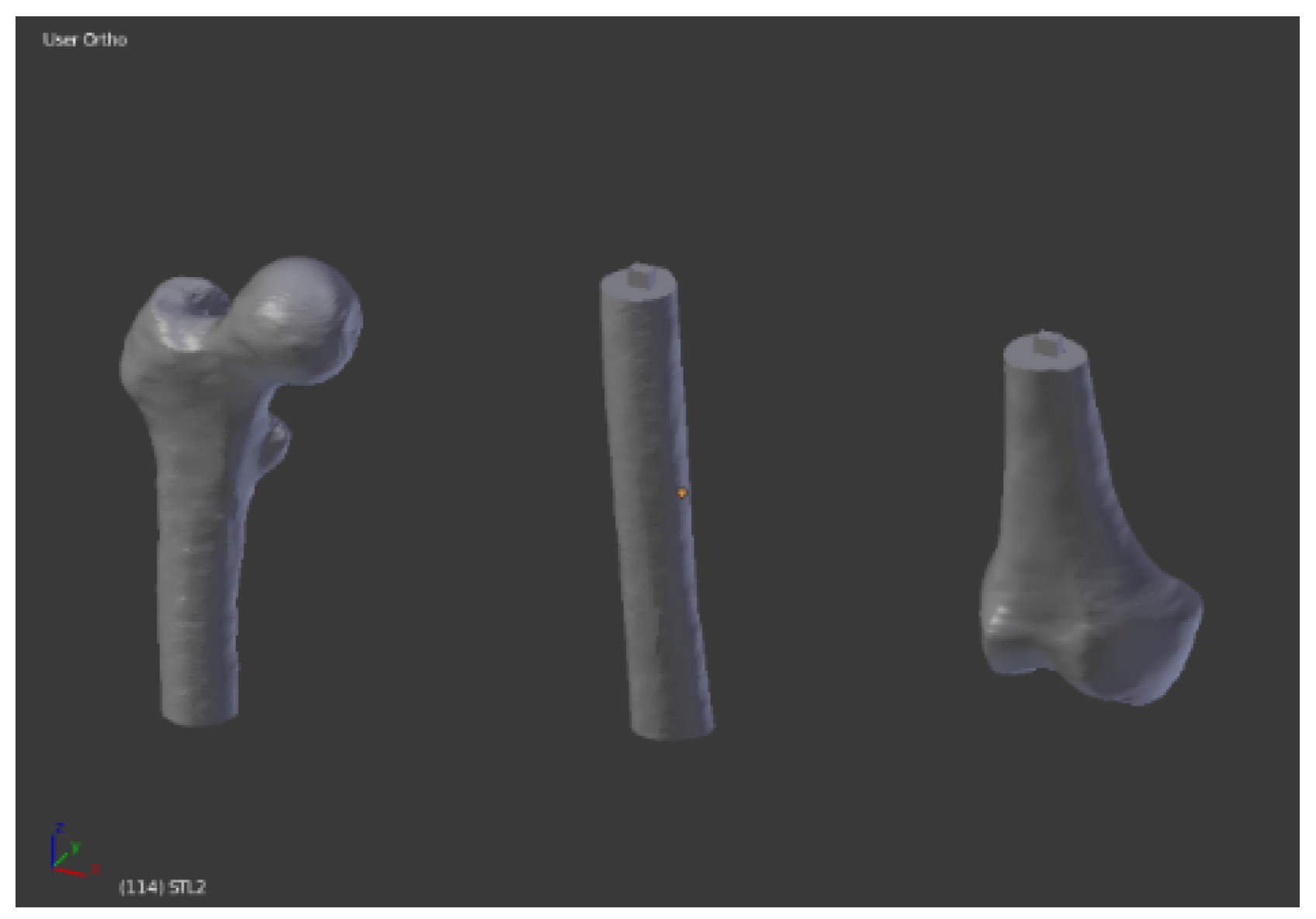
2.1. Imaging Acquisition and Mesh Processing

The proposed method relies on two types of software. The first steps of the process are accomplished by mesh manipulation and mesh repairing software: InVesalius 3.1, MeshLab 2016, Blender 2.79. The final step is performed through the slicing software, Ultimaker Cura 3.4.1, in order to set up the printing parameters. Preoperative computed tomographic data with a section width of 0.6–1 mm were accessed in a standard digital imaging and communications in medicine (DICOM) format. To produce our own model, each DICOM file was imported to imaging software (InVesalius 3.1) and rendered to generate virtual reconstructions of the selected structures. Importing DICOM images, InVesalius allows to visualize the internal structures of interest in the three main axes of the human body: the axial, sagittal, and coronal orientations. Setting different density values, the software permits to highlight specific regions and to generate the 3D model of the selected area, eliminating unnecessary anatomical parts. The image segmentation process arranges the scanned volume into non-overlapping, connected, and homogeneous regions. Segmentation procedure can be manual, where the outlines of the selected image portion are manually adjusted on the display; or automatic, in which the algorithm automatically divides the image into predefined regions that show similar characteristics within these areas. We adopted a semi-automatic approach, since a manual approach is hardly compatible with the number of images to be processed, but an automatic segmentation systems may not guarantee the generation of a 3D printable volume (Figure 2 and Figure 3).
The surface created with InVesalius was exported in “standard triangulation language” (.stl) format, a standard 3D printing format. Then it was repaired and simplified using MeshLab 2016, an open-source software of mesh processing. The main purpose of this software is the mesh repair, by eliminating the mesh irregularities and errors derived from the image segmentation of InVesalius. This is possible with various types of automatic and semi-manual tools. Automatic mesh cleaning filters include the removal of the “orphaned” triangles (vertices and edges situated in the model’s internal cavity, unattached to the rest of the object) through the “Ambient Occlusion” filter. Ambient Occlusion is a shading and rendering technique used to calculate how exposed each point in a scene is to ambient lighting. Ambient occlusion can be seen as an accessibility value that is calculated for each surface point. This function simulates a diffused global illumination throwing rays from every visible point and calculating how many of these actually reach the “sky” (considered as the light source) and how many instead are obstructed. The result is a diffuse, non-directional shading effect that casts no clear shadows but that darkens enclosed areas. As a result, the object is illuminated externally, while internal vertices and faces are darkened. Hence can be easily selected and eliminated, by applying a vertex quality selection (Figure 4). Setting the Min Quality Value = 0, we can select all the internal vertices, edges, and faces. The Max Quality Value need to be very close to the Min Value in order to avoid the elimination of external mesh portions. The mesh exported from MeshLab is a hollow three-dimensional model, not yet ready for 3D printing. It is necessary to fill holes and smooth the surface. Then, the 3D model is divided in multiple parts for two reasons. First of all, the 3D model requires a flat bottom area to have a better platform adherence during the 3D printing phase. Secondly, very large bones can exceed the building volume. We used Blender to optimize our mesh, by filling holes, smoothing the surface, and cutting the 3D model. Furthermore, pins and sockets were created using Blender, in order to accurately join the bone sections. Selecting all the Non-Manifold components, the holes can be filled and the surface can be smoothed with the sculpt command.

2.2. 3D Printing

When the mesh was finally repaired and optimized, the model was ready for 3D printing. We used a low budget EZT3D model T1 3D printer. This printer is a low-cost, entry level Delta printer, which guarantees a great surface finishing due to the low inertia of the moving parts. The nozzle diameter is 0.4 mm; extrusion temperature is 180 °C; no heated bed required; default printing speed of 30 mm/s. Since the thickness of the DICOM data is 0.6–1 mm, layer height has been set to 0.2 mm, in order to guarantee good dimensional accuracy and surface finish. The max resolution of the T1 3D printer is 0.4 mm. These parameters set up allows to speed up the printing without compromising the surface finishing and the dimensional accuracy, crucial for surgical operations. The 3D model was printed in High Temperature Poly-Lactic Acid (HTPLA) by ProtoPasta. After several experiments, we adjusted the baking parameters in order to ensure a complete annealing. The baking stage is performed in a laboratory oven with the following process: the 3D printed model undergoes a heating ramp for 30 min up to 115 °C; then remains one hour at 115 °C; in the end a cooling ramp for 30 min. After the annealing, the HTPLA model can withstand up to 140 °C. The heat strain was avoided using additional volumes, which guaranteed the homogeneous cooling of the model. Then, the model was sterilized according the standard sterilization [4] process for medical devices, in use at our hospital. Briefly, a steam heat (Cisa Production S.r.l., Lucca, Italy) was used, setting the temperature to 134 °C and the total duration of the cycle (including heating and cooling down) to 60 min.

3. Results

3.1. Imaging Acquisition and Mesh Processing
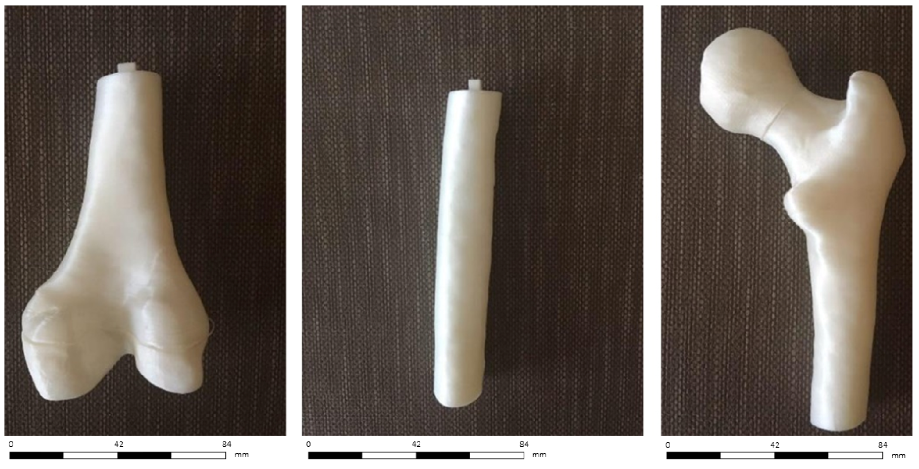
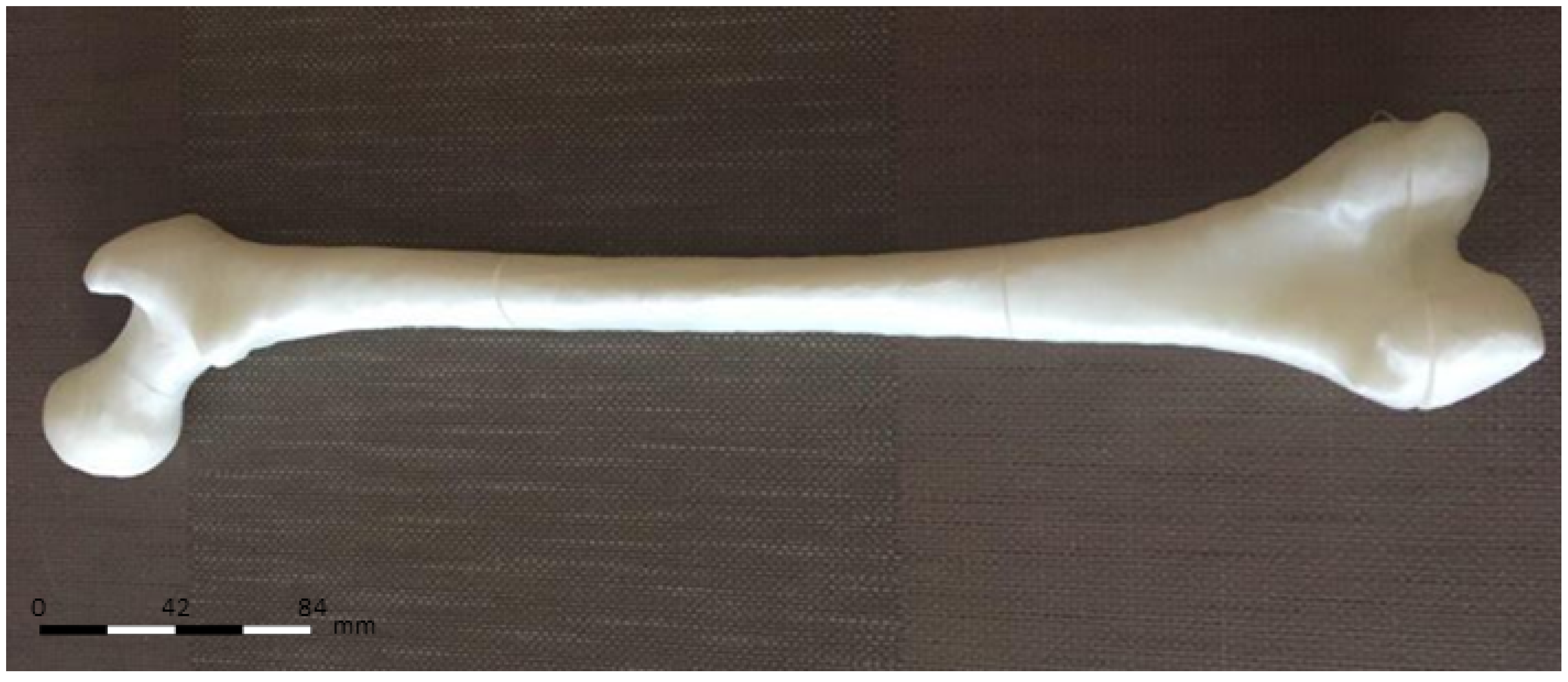
The first case study involved a CT of a femur comprising 986 images and we implemented a semi-automatic approach. Due to the number of images, a predefined density value for the 3D reconstruction was applied. Since the femur geometry was quite simple, holes and segmentation errors were easily repaired with the mesh repairing software. For more complex geometries, for example foot CT, we adopted a semi-automatic approach: firstly, we applied a predefined density value for the overall 3D reconstruction. Then, we changed the density value to edit the complex geometries of: cuneiform bones, metatarsal bones, and phalanges (Figure 5).
This semi-automatic approach was necessary in order to simplify the subsequent use of mesh repairing software. In fact, in these areas, holes and segmentation errors were significant and automatic mesh repairing algorithms could not repair the mesh in a consistent way (Figure 6).
Depending on the complexity of the anatomical district, the meshing process took about 1 to 4 h for the whole model. The femur of the case study was 463 mm long. Since the building volume of the 3D printer is 320 mm height, we divided the femur into three sections. With the insertion of cubes and the application of Boolean operation (Figure 7), dedicated pins were created to allow the mechanical connection of the three portions printed separately (Figure 8).

3.2. 3D Printing

In Table 1 and Table 2, we reported the parameters calibrations test. We observed that the printing parameters could influence the surface finishing in the way that an excessive height of the layers creates a stair step effect on the external surface. Moreover, the extruder multiplier could affect surface quality. On one side, extruding too much material could result in excess plastic that can ruin the outer dimensions of your part (Figure 9), whereas not extruding enough material could result in bad layer adhesion, up to layers separation and gaps and holes in the top layers (Figure 10).
We applied the measuring method proposed by [5]: with the proposed method, the authors designed and positioned measuring balls among all the 3D model, they printed it, and they measured the distance between those balls with a coordinate measuring machine (CMM) to calculate the accuracy of 3D printed medical models. Using the same procedure, the measurement equipment consisted of a Kreon Baces series 100, 7 axes using the contact method of measurement. We positioned the measuring balls according to the indications of the surgeon, generally on the bony prominences. This approach allowed to compare accurate data coming from the Kreon measurement system with the surgeon’s experience. The use of spheres as measuring points mitigated the influence of layers and the stair step effect of FDM technology. Along with the spheres, we also used connecting pins to measure the 3D printed model (Figure 11).
In our case, the error of the femur 3D printed model with respect to the digital model derived from the DICOM data was 0.68%–0.45%. Finally, since the model did not require mechanical resistance, the infill was set at 15% to minimize printing time, avoiding gaps in the top layer (Table 3). In Figure 12 the printing software set up is depicted and in Figure 13 the femur before the assembly stage is depicted.
The assembled model is depicted in Figure 14.

3.3. Cost Analysis

At present, fixed costs for in-house production included acquiring the 3D printer, 180,00 Euros. The turnaround time for in-house production averaged 10–16 h, requiring approximately 1 to 4 h for software processing and printer preparation. The cost for HTPLA filament was 68,00 Euros per kilogram, with 150 g (femur case study) to 200 g (child foot case study) required per model, for a total of 102 Euros for the femur case study up to 135 Euros for the child foot case study. Mean production time ranged approximately from 7–10 h for printing at 15% infill. Postproduction modification (any sanding or removal of support elements) and delivery of the model was approximated at 30–60 min. Other 60–90 min were required for the sterilization process. Because printing was typically performed overnight or during the day without supervision, print time was not considered a billable part of labor costs. Assuming the production of 1 model per week, the approximate labor cost amounted to 2 to 4 h per week and may be estimated as one-twentieth/one-tenth of the workload of a single, fulltime information technology staff member. For the purposes of this study, we based that cost on the extrapolated hourly rate (30 Euros) of a senior information technology employee at our hospital for a total cost of 120 Euros for four hours of work. Total costs per bone model ranged from 1302 Euros for the femur case study up to 1335 Euros for the child foot case study.

4. Discussion

The proposed method allows to fabricate a 1:1 scale model of the bony structures, providing a detailed and realistic representation of the anatomical region of interest, facilitating preoperative planning and subsequent surgery, contributing to increase surgical precision and reduce operative time. In recent years, research focused on the uses of 3D printing technology for surgery [6]. However, most of these applications require expensive and professional 3D printers that conflict with the worldwide contraction of the financial resources spent on healthcare. In clinical practice, rapid prototypes are typically obtained through a third-party vendor. These companies use state-of-the-art machines to construct high-resolution models [7], cutting guides, metal plates, and implantable prostheses [8]; the cost of such technology can reach $500,000 or more. Therefore, the cost of a commercially produced sterilizable bony model, or patient-specific cutting guide varied on a case-by-case basis but was estimated by vendors to exceed 300–500 Euros. The charges for virtual surgical planning services also started at approximately 300–400 Euros. Vendor model turnaround time is generally 3 business days if 1-day shipping is used. If a virtual planning session and customized sterile cutting guides are added to the order, an additional 2 to 3 business days were required. This interval is unsuitable in some situations such as emergency. Our workflow allows a very low cost, in-house 3D printed model production, since it relies on open source software and low cost, “entry level” 3D printers. In our practice a finished, sterilized 3D printed product was available 10 to 16 h after CT scans acquisition and it cost approximately 130 Euros per model. Moreover, the choice of a low-cost 3D printer was dictated by the fact that the 3D printer can become an integral part of the CT process. From this perspective, a hospital can afford several low budget 3D printing stations to handle more cases at the same time with greater ease. Furthermore, by implementing a low-cost 3D printer in the process described, even hospitals and emergency services with fewer resources could be able to benefit from the advantages of patient specific anatomical models. For this reason, Stereolithography technology has been rejected since the set-up costs are much higher even than mid-range FDM 3D printers: The High Temperature resins available on the market are more expensive than HTPLA filament. For example, 1 lt of High Temp resin by Formlabs costs 229 Euros while 1 kg of HTPLA by ProtoPasta costs 68 Euros. The higher cost of a SLA 3D printer and the SLA resin are unsuitable with emergency services or small hospitals with few resources. In [9] the authors pioneered the use of Fused Deposition Modeling (FDM) for 3D medical models but the 3D printer was a semi-professional end-user printer. In [10] the 3D model is printed in Acrylonitrile Butadiene Styrene (ABS), which is more resistant than PLA in terms of Rockwell Hardness: R105 to R110 for ABS, R70 to R90 for PLA [11]. However, ABS material presents more technical difficulties in printing. ABS 3D printers demand a heated bed and a closed printing chamber for two reasons: a controlled and forced cooling is required in order to avoid warping of bottom layers and to avoid toxic gas escape. In general, most common ABS filaments are printed at higher temperatures than commercially available PLA filaments: the ABS extruding temperature range is 220–240 °C, while PLA extruding temperature range is 180–220 °C. For these reasons, the use of ABS commits a more expensive equipment. The key feature of our 3D printing process is the material chosen for the printing. The 3D model is printed in HTPLA. The advantages of HTPLA are multiple. HTPLA can be printed at 200 °C or less and without heated bed, so it doesn’t require expensive equipment. HTPLA as printed has poor temperature stability, loosing significant stiffness at temperatures not much above 50 °C. The HTPLA can be heat treated for higher temperature stability. Actually, several polymers available on the market for 3D printing are capable of withstanding high temperatures, for example, PolyCarbonate (PC) and ABS. However, as mentioned before, ABS is not as easy 3D printable as PLA: 3D printing ABS requires a heated bed and a heated chamber in order to avoid warping and layers delamination, caused by an uncontrolled cooling. Moreover, 3D printing ABS generates toxic gasses and their uncontrolled release in hospitals or emergency clinics should be avoided. On the other hand, PC is the commercial 3D printing filament with the highest heat resistance. This feature is both a benefit and a problematic characteristic, as it is even more prone to warping and splitting than ABS filament. As such, this material needs high temperatures in order to extrude and have proper layer adhesion. PC filament will typically flow well in the range of 290–310 °C, nozzle temperatures much higher than the low-budget 3D printers’ working temperatures, which are limited to 250–270 °C. On the platform side, optimal bed temperature for layer adhesion and curing should be kept between 145–150 °C. Even with PC, the 3D printer building volume should be closed in order ot avoid uncontrolled release of toxic gasses and forced air recirculation should be provided to the building volume. Other FDM High Temp filaments, such as PolyEther Ether Ketone (PEEK) and PolyEtherImide (PEI), require higher printing temperature, higher building volume temperature, and stricter cooling control systems. HTPLA by ProtoPasta, at the moment, is the only 3D printing filament capable of offering the easiness of printing of PLA combined with high temperature resistance. Finally, comparing to [12], our method diminishes the wastage of material since the model is printed in multiple pieces, minimizing the use of support pillars for unsupported areas. Furthermore, printing the model in multiple pieces speeds up the printing step. The present study must be seen in light of some limitations: to date, we printed only bony models; therefore, the impact of the mechanical features of HTPLA (brittleness, stiffness) was not investigated since it was not relevant at this phase of the study. To this purpose, the research is ongoing and more data will be available from the use of cutting guides or customized tools during surgery. Moreover, we tried only the steam sterilization that is easy, low-cost, and very effective to our purpose; additional research should be conducted to investigate the possible changes of the model with other methods of sterilization. Finally, prospective randomized clinical studies are advancing to assess the effectiveness of this technology, in terms of risk-benefits and cost-benefits ratio, especially in pediatric orthopedics and traumatology.

5. Conclusions

In this paper, we described the methodology to produce very-low cost, patient-specific, sterilizable 3D printed products, through an in-house, user-friendly process. Starting from CT scans, we reconstructed the patient anatomy and we prepared the 3D model for 3D printing. This technology has been successfully implemented at our center of pediatric orthopedics and traumatology, and it is currently used for clinical, educational, and surgical needs. We believe that our method is an appealing alternative to high-end commercial products, being superior for cost and speed of production. It will be advantageous especially for small and less affluent hospitals that could produce customized sterilizable tools with little investment and high versatility.

Author Contributions

Conceptualization, F.O. and L.F.; Methodology, G.M.S.; Data Curation, M.N.; Formal Analysis, A.L.; Validation, S.S., E.M., G.T., G.G., S.S. and P.Z.; Writing—original draft, M.N., F.O.; Manuscript editing and response to reviewers, G.T., F.O.

Conflicts of Interest

The authors declare no conflict of interest.

References

  1. De Amicis, R.; Ceruti, A.; Francia, D.; Frizziero, L.; Simões, B. Augmented Reality for virtual user manual. Int. J. Interact. Des. Manuf. 2018, 12, 689–697. [Google Scholar] [CrossRef]
  2. Frizziero, L.; Francia, D.; Donnici, G.; Liverani, A.; Caligiana, G. Sustainable design of open molds with QFD and TRIZ combination. J. Ind. Prod. Eng. 2018, 35, 21–31. [Google Scholar] [CrossRef]
  3. Caligiana, G.; Francia, D.; Liverani, A. CAD-CAM integration for 3D hybrid manufacturing. Lect. Notes Mech. Eng. 2017, 329–337. [Google Scholar] [CrossRef]
  4. Mitsouras, D.; Liacouras, P.; Imanzadeh, A.; Giannopoulos, A.; Cai, T.; Kumamaru, K.K.; George, E.; Wake, N.; Caterson, E.J.; Pomahac, B.; et al. Medical 3D Printing for the Radiologist. Radiographics 2015, 35, 1965–1988. [Google Scholar] [CrossRef] [PubMed] [Green Version]
  5. Salmi, M.; Paloheimo, K.-S.; Tuomi, J.; Wolff, J.; Mäkitie, A. Accuracy of medical models made by additive manufacturing (rapid manufacturing). J. Cranio-Maxillofac. Surg. 2013, 41, 603–609. [Google Scholar] [CrossRef] [PubMed]
  6. Matsumoto, J.S.; Morris, J.M.; Foley, T.A.; Williamson, E.E.; Leng, S.; McGee, K.P.; Kuhlmann, J.L.; Nesberg, L.E.; Vrtiska, T.J. Three-dimensional Physical Modeling: Applications and Experience at Mayo Clinic. RadioGraphics 2015, 35, 1989–2006. [Google Scholar] [CrossRef] [PubMed]
  7. Francia, D.; Caligiana, G.; Liverani, A.; Frizziero, L.; Donnici, G. PrinterCAD: A QFD and TRIZ integrated design solution for large size open moulding manufacturing. Int. J. Interact. Des. Manuf. 2018, 11, 81–94. [Google Scholar] [CrossRef]
  8. Popov, I.; Onuh, S.O. Reverse engineering of pelvic bone for hip joint replacement. J. Med. Eng. Technol. 2009, 33, 454–459. [Google Scholar] [CrossRef] [PubMed]
  9. Bortolotto, C.; Eshja, E.; Peroni, C.; Orlandi, M.A.; Bizzotto, N.; Poggi, P. 3D Printing of CT Dataset: Validation of an Open Source and Consumer-Available Workflow. J. Digit. Imaging 2016, 29, 14–21. [Google Scholar] [CrossRef] [PubMed]
  10. Bizzotto, N.; Sandri, A.; Regis, D.; Romani, D.; Tami, I.; Magnan, B. Three-Dimensional Printing of Bone Fractures: A New Tangible Realistic Way for Preoperative Planning and Education. J. Abbr. 2008, 10, 142–149. [Google Scholar] [CrossRef] [PubMed]
  11. Farbman, D.; McCoy, C. Materials Testing of 3D Printed ABS and PLA Samples to Guide Mechanical Design. In Proceedings of the ASME 2016 11th International Manufacturing Science and Engineering Conference, Blacksburg, VA, USA, 27 June–1 July 2016. [Google Scholar]
  12. Brouwers, L.; Pull ter Gunne, A.F.; de Jongh, M.A.C.; van der Heijden, F.H.W.M.; Leenen, L.P.H.; Spanjersberg, W.R.; van Helden, S.H.; Verbeek, D.O.; Bemelman, M.; Lansink, K.W.W. The Value of 3D Printed Models in Understanding Acetabular Fractures. 3D Print. Addit. Manuf. 2018, 5, 37–46. [Google Scholar] [CrossRef] [Green Version]
Figure 1. Computed Tomography (CT) conversion workflow.
Applsci 09 00708 g001
Figure 2. Segmentation errors in the medial epicondyle of a femur.
Applsci 09 00708 g002
Figure 3. Holes in the mesh of the femur in the medial epicondyle area.
Applsci 09 00708 g003
Figure 4. Mesh cleaning in Meshlab.
Applsci 09 00708 g004
Figure 5. Segmentation errors in the cuneiform bones of a child foot.
Applsci 09 00708 g005
Figure 6. Holes in the mesh in the cuneiform bones area of a child foot.
Applsci 09 00708 g006
Figure 7. Pin positioning in Blender.
Applsci 09 00708 g007
Figure 8. Three sections ready to be printed.
Applsci 09 00708 g008
Figure 9. Blobs and zits on the external walls.
Applsci 09 00708 g009
Figure 10. Gaps in the top layer.
Applsci 09 00708 g010
Figure 11. 3D printed model misuration step with Kreon Baces unit.
Applsci 09 00708 g011
Figure 12. 3D printing set up in Ultimaker Cura.
Applsci 09 00708 g012
Figure 13. 3D printed femur sections.
Applsci 09 00708 g013
Figure 14. 3D printed femur assembled.
Applsci 09 00708 g014
Table 1. Layer thickness calibration (extruder multiplier 100%; infill 15%).
Layer Thickness [mm]Printing Time [h:m]Measured Error
0.0528 h and 28 min0.23% ± 0.32%
0.115 h 7 min0.45% ± 0.15%
0.27 h and 37 min0.68% ± 0.45%
0.34 h and 58 min0.83% ± 0.52%
Table 2. Extruder Multiplier calibration (layer thickness 0.2 mm; infill 15%).
Extruder Percentage [%]Printing Time [h:m]Type of Error
907 h 37 minWeak Infill; Under-Extrusion; Gaps in Top Layers; Gaps Between Infill and Outline
1007 h 37 minNone
1057 h and 37 minBlobs and Zits; Over-Extrusion
1107 h 37 minBlobs and Zits; Over-Extrusion; Curling or Rough Corners
Table 3. Infill percentage calibration (layer thickness 0.2 mm; extruder multiplier 100%).
Infill Percentage [%]Printing Time [h:m]Type of Error
105 h 7 minGaps in Top Layers
157 h 37 minNone
2010 h and 17 minNone
2512 h 42 minNone

