Abstract
Cobalt-Nickel (Co-Ni) alloy coatings were prepared by jet electrodeposition on brass substrate under different Co2+/Ni2+ ratio contents (M = 2:1, 1:1, 1:2 and 1:3) and solution flow rates (from 2.0 to 4.5 L/min). The surface morphology, element content, and phase structure of the coating were observed by scanning electron microscope (SEM), energy dispersive spectrometer (EDS), and X-ray diffractometer (XRD). The hardness and wear resistance of the coatings were also measured. The results showed that the Co content in coatings was greater than 70%, no matter at what flow rate and concentration. With an increase of the flow rate, the Co content in the coating increases, and the grain size on the surface of the coating decreases, which leads to increased hardness of the coating. However, the flow rate of the plating solution has little effect on the grain growth orientation, and the phase structure is dominated by the elemental content of the coating. The coatings are in a single phase of hexagonal close-packed (HCP) when the Co content is more than 80%, while the coatings are in dual phases of the HCP and face-centered cubic (FCC) when the Co content is less than 80%. With an increase in the Co content, the grain size decreases, and consequently, the hardness and wear resistance of the alloy increase. A Co-Ni alloy coating with stable composition can be obtained when the ratio of Co2+ to Ni2+ is 2:1.
1. Introduction
Electrodeposited cobalt-nickel (Co-Ni) alloy coatings usually have superior properties that are better than both pure Co and Ni metals [1]. The reason for this is its microstructure, which can be varied as a function of composition. The Co-Ni co-deposition is an anomalous process, in which the deposition of Co is preferred, while that of Ni is inhibited [2]. Therefore, the Co/Ni atom ratio in the coating is generally higher than the Co2+/Ni2+ cation ratio in the plating solution. Ni-Co co-deposition is also a non-equilibrium one, and is controlled by the mass transfer of Co2+ in the solution [3]. When Co content in the coating changes, the phase of coating’s structure may change from HCP to FCC or HCP + FCC [4], therefore showing dramatic variation in its properties. Coatings with HCP structure have better wear resistance than those with FCC structure, while coatings with FCC structure possess better corrosion resistance than those with HCP structure [5,6,7]. Therefore, Ni-Co coatings have found a wide range of applications, including in microelectromechanical system (MEMS) due to their good soft magnetic properties [8,9], or for surface protection due to their good resistance to corrosion, temperature and/or abrasion [10,11].
Electrodeposition is commonly undertaken in a plating bath, and it has been found that many parameters, such as bath composition [4,12,13], pH [14], current density [15,16], and others, will significantly affect the deposition process. E. Gómez et al. [17] studied the influence of plating solution on the electroplating with grooves, and the results showed that the coating surface was uniform, fine and dense when the plating solution was stirred. This is because the stirring of the plating solution in the bath plating affects the mass transfer of the cation. When the current density is fixed, the Co content in the coating is associated with the ratio of Co2+/Ni2+ concentration in the plating solution. Similarly, electrodeposition can be carried out in jet plating format. Qiao et al. [18] studied the effect of plating solution flow rate on the composition and properties of jet electrodeposited Co-Ni alloy coatings. The results showed that the flow rate increased the Co content in the coatings, while reducing the thickness of the diffusion layer with refined grain and increasing the microhardness of the coating. The increase of the solution flow rate in the jet electrodeposition process is equivalent to the increase of the stirring speed in the plating bath.
The plating solution flow rate is also one of the key parameters in jet electrodeposition for preparing particle composite coatings. This affects the mass transfer of the particles and the entry of the particles into the composite coating [19]. When jet electrodepositing the Co-Ni alloy matrix and particle composite coating, the plating solution flow rate may affect both the Co content and the particle content in the coating. In this case, it is difficult to tell the property effect from the alloy matrix between the composited particles. Therefore, it is necessary to obtain high flow-independent quality of Co-Ni coating by jet electrodeposition. Unfortunately, there is still a lack of research on this. In this paper, we conducted a systematic investigation of the effect of jet flow rate on the microstructure and mechanical properties of jet electrodeposited coatings. Six different flow rates and four kinds of solutions were tested.
2. Experimental Details
The sample substrate is made of brass sheet 24 mm in diameter and 6 mm thick. Before the electrodeposition, the surface of the sample is polished with an 800-mesh sandpaper, and is then electrochemically cleaned using a brush plating device.
The jet electrodeposition equipment consists of a direct current (DC) supply power (produced by Huake Elelctronic Equipment Co., Ltd.), a numerical control (NC) platform, an electrode plating solution reservoir, a spray gun, a control valve, a circulating pump and other units, as shown in Figure 1. The nozzle of the spray gun has an internal diameter of 6 mm. The spray gun reciprocates linearly and travels at a velocity of 1.2 mm/s. The vertical distance from the bottom of the nozzle to the sample surface is 10 mm.
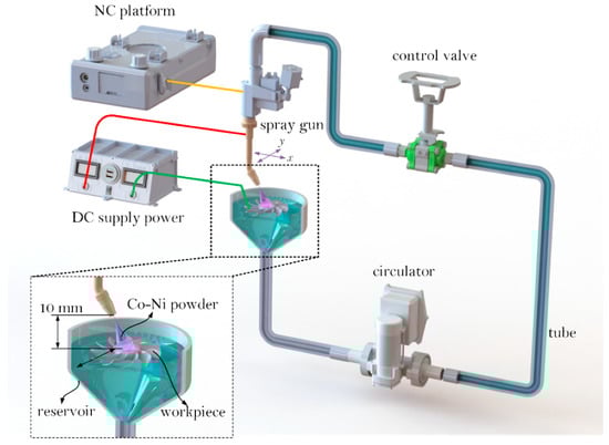
Figure 1.
Schematic of jet electrodeposition system. NC: numerical control; DC: direct current.
The total mass of CoSO4·7H2O and NiSO4·6H2O was fixed at 300 g/L, and the mass concentration ratio of Co2+:Ni2+ was referred to as M. Four kinds of plating solution were prepared with M 2:1, 1:1, 1:2 and 1:3. Additionally, the solution was mixed with NaCl at 20 g/L and HBO3 at 30 g/L to maintain a pH value of 3–4. Jet electrodeposition was conducted at room temperature with a current density of 40 A/dm2 and varying the flow rate from 2.0 to 4.5 L/min.
The Nova Nano 450 field emission scanning electron microscope (SEM) was used to observe the surface morphologies of the coatings. The content of Co and Ni in the coatings was measured using an Energy Disperse Spectroscopy (EDS). The DX-2700 X-ray diffractometer was used to analyze the phase structure of the coatings. The surface roughness of the coating was measured by a 2300A-RC profile roughness measuring instrument at a scan speed of 0.5 mm/s and a scan length of 8 mm. Dry wear test was also conducted on a MFT-R4000 high-speed reciprocating friction wear tester. The friction pair was a GCr15 steel ball with a diameter of 4 mm, and the wear scar length was 5 mm at 5 Hz frequency for 10 min. The wear volume was determined from the wear scars using an OLS4000 3D laser microscope. A Buehler automatic microhardness tester was used to measure the microhardness of the coating at 50 g load and 15 s duration. The average of five tests was taken for each sample.
3. Results and Discussion
3.1. Contents of the Coatings
Figure 2 shows the relationship between flow rate and Co content in the coating. It can be seen that the Co content in coatings is greater than 70%, no matter at what flow rate and concentration. The highest Co concentration is up to 96% for M = 2:1 at 4.5 L/min flow rate, which shows a significant anomalous co-deposition. This is similar to what Gómez et al. observed. The formation of Co(OH)+ in the vicinity of the cathode suppresses the passage of Ni2+ but not the Co2+, so the precipitation of Ni is suppressed while the Co content is enhanced [20]. It is also found that the Co content in the coating increases with the increasing flow rate. This is because the jet electrodeposition is a non-equilibrium process, and the metal cations are controlled by the mass transfer in the liquid. Due to the cathode concentration polarization, the consumption rate of metal cations near the cathode is lower than the supplement rate of the ions. The flow rate of the plating solution will affect the mass transfer rate of Co2+ and Ni2+ in the jet electrodeposition, and an increase in the flow rate will help to reduce the concentration polarization. Therefore, the solution flow rate has a greater influence on the mass transfer rate of Co2+ than that of Ni2+. The degree increase of Co content in the coating is different for different solutions. For M at 2:1, 1:1, 1:2, and 1:3, the Co content in the coating increased by 0.63%, 1.67%, 6.75%, and 8.54%, respectively. The larger the M value is, the smaller the Co content increase will be. Obviously, the influence on the mass transfer rate of metal cations is reduced when the concentration of Co2+ in the solution is higher.
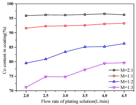
Figure 2.
Co content in the coatings with different flow rate and M.
3.2. Phase Structure of the Coatings
Figure 3 shows the XRD patterns of the coatings obtained at different flow rates. The analytical results show that Co-Ni alloys are all solid solutions, with Co solvent and Ni solute. When the M of the plating solution is 2:1 or 1:1, the coating is in the structure of HCP (Co). The main diffraction pattern is (110), (100), (101), and the texture direction (110) of the coating does not change with the flow rates. When the M is 1:2 and the flow rate is 2.0 L/min, the (111) peak of the FCC structure appears, except for the diffraction peaks of the HCP. When M is 1:3 in the bath, the diffraction peaks of the FCC (111) can be found at many more flow rates. This means that both HCP and FCC coexist in these coatings. The main reason for the change of the coating structure with different flow rates is that the flow rate changes the Co content in the plating coating. When the M in the plating solution is 2:1 and 1:1, the Co content in the coating does not change significantly, so does the structure of coatings. When M is 1:2 and 1:3, the Co content in the coating is lower than 80%, and the coating coexists in two phases.
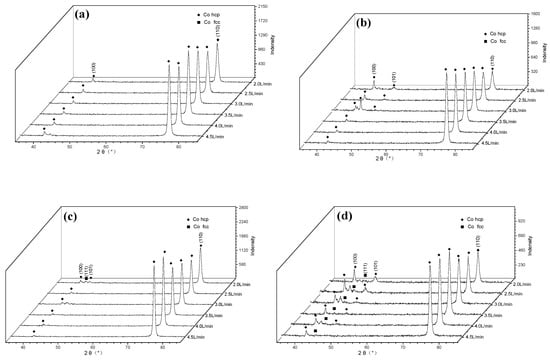
Figure 3.
X-ray diffraction patterns of the Co-Ni coatings obtained at different mass concentration. ratios: (a) M = 2:1 (b) M = 1:1, (c) M = 1:2, (d) M = 1:3.
3.3. Surface Morphology of the Coatings
Figure 4, Figure 5, Figure 6 and Figure 7 show the surface morphology of the coatings under different solution flow rates. It can be seen that the grain sizes on surface decrease with the increasing flow rate. This change is more dramatic at higher M values. When M is 2:1 or 1:1, the surface of the coating is generally uniform and angularly conical tapered crystal at lower flow rates. As the flow rate of the plating solution increases, the grain size of the coating surface decreases slightly, and the surface becomes smoother. This trend is more obvious when M is at 1:1 than at 2:1. Since the Co content in the two plating baths is basically not affected by the flow rate of the plating solution, the plating solution flow rate has a direct effect on the plating surface. This is because the flow rate of the plating solution reduces the range of the diffusion layer on the surface of the cathode, which increases nucleation during deposition and leads to fine grains. In addition, at the same flow rate, the grain size of Co-Ni coatings obtained with M at 2:1 is smaller than that at 1:1. When M is at 1:2 or 1:3 in the plating solution, the variation of surface grain structure is more significant as the flow rate of the plating solution increases. This is because the Co content of coatings increases with the increasing flow rate, leading to decreasing grain size. Meanwhile, the increase of the flow rate reduces the thickness of the diffusion layer. At the same time, the kinetic regime may switch to a mixed or activation-controlled regime because of reducing mass transport resistance, and the surface of the Co-Ni coatings are further refined.
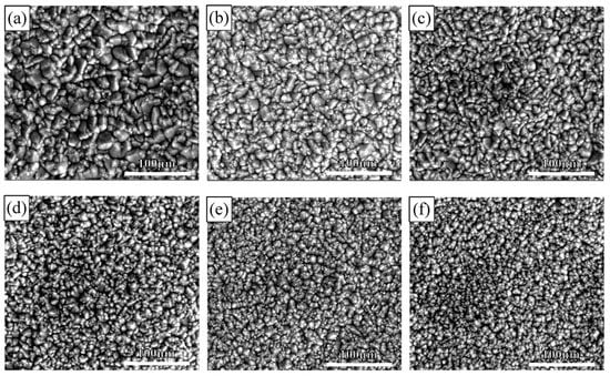
Figure 4.
Surface morphology of coatings obtained with M = 2:1 in the plating solution at different flow rates: (a) 2.0 L/min, (b) 2.5 L/min, (c) 3.0 L/min, (d) 3.5 L/min, (e) 4.0 L/min, (f) 4.5 L/min.
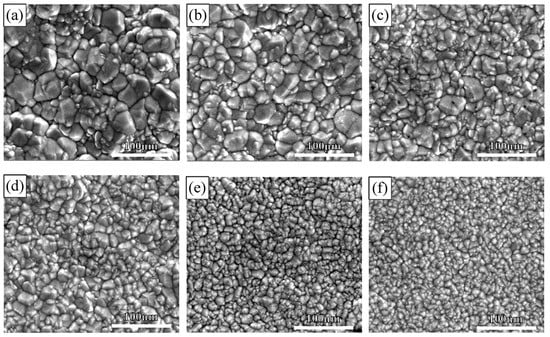
Figure 5.
Surface morphology of coatings obtained with M = 1:1 in the plating solution at different flow rates: (a) 2.0 L/min, (b) 2.5 L/min, (c) 3.0 L/min, (d) 3.5 L/min, (e) 4.0 L/min, (f) 4.5 L/min.
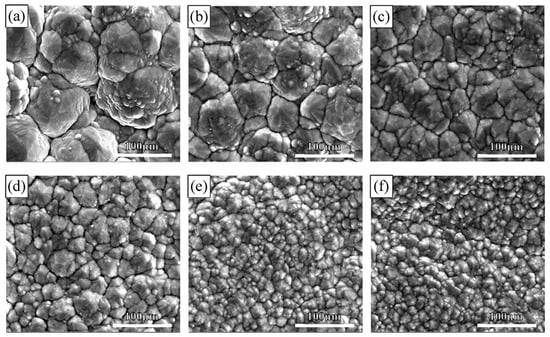
Figure 6.
Surface morphology of coatings obtained with M = 1:2 in the plating solution at different flow rates: (a) 2.0 L/min, (b) 2.5 L/min, (c) 3.0 L/min, (d) 3.5 L/min, (e) 4.0 L/min, (f) 4.5 L/min.
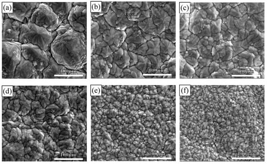
Figure 7.
Surface morphology of coatings obtained with M = 1:3 in the plating solution at different flow rates: (a) 2.0 L/min, (b) 2.5 L/min, (c) 3.0 L/min, (d) 3.5 L/min, (e) 4.0 L/min, (f) 4.5 L/min.
The variation of the coating surface with flow rate can be explained by mass transfer theory. According to diffusion mass transfer theory [21], the diffusion thickness can be expressed as:
where δ is the thickness of the diffusion layer, Di is the diffusion coefficient, u0 is the tangential initial velocity of the liquid flow, μ is the dynamic viscosity coefficient, and y is the distance from a point on the surface of the cathode to the impact point y0. For the same plating solution, increasing the flow rate of the plating solution can reduce the thickness of the diffusion layer, which is beneficial to the limited current density of the electrodeposition and also the cathode overpotential [22]. The size and number of nuclei are controlled by overpotential and can be expressed by Kelvin’s electrochemical formula [23]:
where τ is the radius formed by the critical nucleus, ε is the surface energy, V is the atomic volume in the crystal, Z is the elementary charge, and η is the overpotential. It can be seen from the Kelvin formula that when there is a high overpotential, a small crystal nucleus can be formed. Therefore, an increase in the flow rate of the plating solution facilitates the formation of a small crystal nucleus, whereby the size of the crystal grains is reduced, and the structure is refined.
3.4. Surface Roughness of Coatings
To further verify the influence of the plating flow rate on the surface texture of the coatings, the surface roughness of the coating was measured. Figure 8 shows the relationship between the surface roughness of the coatings and the flow rate of the plating solution. It can be seen that the surface roughness of the coatings obtained by the four plating solutions decreases with the increase of the flow rate of the plating solution. This indicates that the increase of the flow rate of the plating solution makes the surface structure of the plating layer finer and smoother. When the M value in the plating solution is higher, the surface roughness of the plating layer is relatively lower under the same plating solution flow rate. When the M value in the plating solution is 2:1, the surface roughness of the plating layer is the lowest, which is consistent with the change of the observed surface morphology. It is obvious that the higher the Co content in the coating is, the smother the surface of the coating will be.
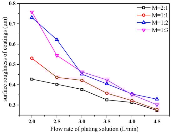
Figure 8.
Surface roughness of coatings.
3.5. Cross-Section Morphology of Coatings
Figure 9 shows the cross-sectional morphology of the coatings with different mass concentration ratios of Co2+:Ni2+ at a solution flow rate of 2.5 L/min. As seen from the results, the cross-section of each coating is dense and there are no gaps or bubbles between the interface of the coating and the substrate. When M is 2:1 and 1:1, as shown in Figure 9a,b, the uppermost edge of the coating is quite smooth, without any significant protrusions. When M in the plating solution is 1:2 and 1:3, as shown in Figure 9c,d, the surface of the plated layer becomes irregular and serrated. The profile of the cross-section morphology is similar to that of the surface morphology. This is attributed to the high content of Co in the coating, which generates the fine grains and relatively smooth surface of the coating.
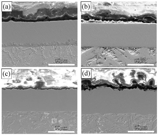
Figure 9.
The cross-sectional morphology of the coatings with different M in the plating solution when the flow rate is 2.5 L/min: (a) M = 2:1, (b) M = 1:1, (c) M = 1:2, (d) M = 1:3.
3.6. Microhardness and Wear Volume of the Coatings
Figure 10 shows the variation of the microhardness of the coatings obtained with different concentration ratios of Co2+:Ni2+ and solution flow rates. It can be seen that the microhardness of the coatings generally increases with the increasing flow rate. The microhardness for M = 2:1 is the highest (about 420 @ (HV)) for all flow rates, and the microhardness for M = 1:3 is the lowest for each flow rate. There is only a small change for M = 2:1 or 1:1, but a large change for M = 1:3. The microhardness of the coating is mainly related to the content of the elements and the grain size in the coating [19]. In Co-Ni alloy coatings, the presence of Ni element plays an important role in solid solution strengthening. The increase of the plating solution flow rate decreases the content of Ni in the coating, which leads to the reduction of the solid solution strengthening. On the other hand, the decrease of the Ni content makes the grain size of the coatings smaller, leading to the enhancement of the dominating fine grain strengthening. This dominated grain strengthening mechanism of the coating can explain the higher microhardness for M = 2:1 or 1:1. As the grain size for M = 1:2 or 1:3 decreases significantly with the increasing flow rate, there is a relatively large change in the microhardness of the coating.
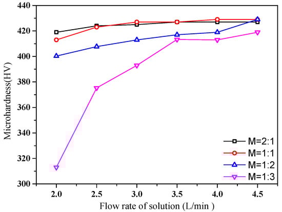
Figure 10.
Microhardness of the coatings.
Figure 10 shows the wear volume of coatings prepared with different mass concentration ratios of Co2+:Ni2+ and solution flow rates. It can be seen that when M = 1:2 or 1:3, the wear volume of the coating remains largely unchanged. When M is 1:2, the wear volume of the coating decreases slightly. When M is 1:3, the wear volume of the coatings is high, and the wear volume of the coating decreases rapidly. Therefore, the wear volume of the coating is affected by the element content, microhardness, and surface microstructure of the coatings. When M is 2:1 or 1:1 in the plating solution, the increase of the flow rate of the plating solution does not substantially change the element content of the coating, and the decrease in the crystal size of the coatings and the reduction in the surface roughness are not obvious, so that the wear volume of the coating changes little. When M is 1:2 or 1:3 in the plating solution, the increase of the flow rate of the plating solution increases the Co content in the coatings, and the grain of the coatings are obviously refined, the surface roughness is reduced, and the microhardness is increased, so the wear volume of the coating is reduced and wear resistance is improved.
Figure 11 shows the wear volume of coatings prepared with different mass concentration ratios of Co2+:Ni2+ and solution flow rates. It can be seen that the wear volumes are relatively small for all coatings, except for M = 1:3. The coating with M = 2:1 has the highest wear resistance among all coatings. The wear resistance decreases gradually with the increasing Co2+:Ni2+ ratio. There is also a decreasing trend in the wear volume with the increasing flow rate for all coatings. In general, the trend of wear volume variation is inversely correlated with the microhardness variation of the coating. It can be seen that the wear volume of the coating is affected by the element content, microhardness, and surface microstructure of the coatings.
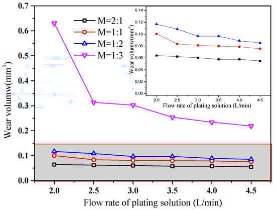
Figure 11.
Wear volume of the coatings.
When M is 2:1 in the plating solution, the coating has a high Co content and fine grain for all flow rates, so the wear resistance is high and there is no substantial variation among the coatings. For M = 1:3 in the plating solution, there is a large variation in grain size, surface roughness, and microhardness as the flow rate changes, and similar for the wear resistance of this coating. It can be seen that the flow rate plays a significant role in the performance of Co-Ni coatings by jet electrodeposition, and that high-quality flow-independent Co-Ni coatings can be obtained when Co2+/Ni2+ ratio in the solution is 2:1.
4. Conclusions
Co-Ni alloy coatings were prepared by jet electrodeposition on brass substrate under different Co2+/Ni2+ ratio contents (M = 2:1, 1:1, 1:2 and 1:3) and solution flow rates (from 2.0 to 4.5 L/min). The influence of Co-Ni content and flow rate of the plating solution on the coating morphology and mechanical properties was investigated. Following are the main conclusions of the present studies
- (1)
- Increasing the flow rate of the plating solution reduces the concentration polarization of the cathode, so that the Co content in the coating increases accordingly. The range of increase is affected by the ratio of the main salt concentration of Co and Ni. If the ratios of Co2+/Ni2+ in the plating solution are 2:1, 1:1, 1:2, and 1:3, the change ranges of Co content are 0.63%, 1.67%, 6.75%, and 8.54%, respectively, when the flow rate changes from 2 to 4.5 L/min.
- (2)
- The surface morphology of the coating is determined by the flow rate of the plating solution. When plated at a higher flow rate, the coatings have a higher Co content, with a smaller grain size and a denser structure. The phase structure of the coating is mainly determined by the content of Co in the coating. The flow rate of the plating solution changes the Co content in the coating, so does the phase structure of the coating. When the Co content is more than 80%, the coating is a single HCP structure. When the Co content is less than 80%, the coating has a structure with both HCP and FCC coexisting.
- (3)
- The mechanical properties of the coating are mainly determined by the grain size. The coating with higher Co content has a smaller grain size, higher hardness, and stronger wear resistance. The increase of the flow rate increases the Co content in the coating, reducing the grain size of the coating, increasing the hardness of the coating, and decreasing the wear volume.
- (4)
- The flow rate plays a significant role in the performance of Co-Ni coatings by jet electrodeposition. High-quality flow-independent Co-Ni coatings can be obtained when Co2+:Ni2+ ratio in the solution is 2:1.
Author Contributions
Writing—Original draft, Q.Z.; Supervision, J.T.; Resources, L.M.; Methodology. F.X.; Investigation, H.Z.; Data Curation, Z.Y.
Funding
This publication was funded by a grant from the Major State Key Research and Development Program of China (No. 2018YFB407401).
Conflicts of Interest
The authors declare no conflict of interest.
References
- Bakhit, B.; Akbari, A.; Nasirpouri, F.; Hosseini, M.G. Corrosion resistance of Ni–Co alloy and Ni–Co/SiC nanocomposite coatings electrodeposited by sediment codeposition technique. Appl. Surf. Sci. 2014, 307, 351–359. [Google Scholar] [CrossRef]
- Yu, M.M.; Li, H.Y.; Wang, Y. Study on Present Situation and New Trends of the Electrodeposition of Nickel-Cobalt Alloy. Adv. Mater. Res. 2012, 535–537, 973–976. [Google Scholar] [CrossRef]
- Li, Y.; Jiang, H.; Huang, W.; Tian, H. Effects of peak current density on the mechanical properties of nanocrystalline Ni–Co alloys produced by pulse electrodeposition. Appl. Surf. Sci. 2008, 254, 6865–6869. [Google Scholar] [CrossRef]
- Karpuz, A.; Kockar, H.; Alper, M.; Haciismailoglu, M. Electrodeposited Ni–Co films from electrolytes with different Co contents. Appl. Surf. Sci. 2012, 258, 4005–4010. [Google Scholar] [CrossRef]
- Wang, L.; Gao, Y.; Xue, Q.; Liu, H.; Xu, T. Graded composition and structure in nanocrystalline Ni–Co alloys for decreasing internal stress and improving tribological properties. J. Phys. D Appl. Phys. 2005, 38, 1318–1324. [Google Scholar] [CrossRef]
- Wang, L.; Gao, Y.; Liu, H.; Xue, Q.; Xu, T. Effects of bivalent Co ion on the co-deposition of nickel and nano-diamond particles. Surf. Coat. Technol. 2005, 191, 1–6. [Google Scholar] [CrossRef]
- Srivastava, M.; Selvi, V.E.; Grips, V.W.; Rajam, K.S. Corrosion resistance and microstructure of electrodeposited nickel–cobalt alloy coatings. Surf. Coat. Technol. 2006, 201, 3051–3060. [Google Scholar] [CrossRef]
- Zhang, Y.H.; Ding, G.F.; Cai, Y.L.; Wang, H.; Cai, B. Electroplating of low stress permalloy for MEMS. Mater. Charact. 2006, 57, 121–126. [Google Scholar] [CrossRef]
- Pellicer, E.; Varea, A.; Pané, S.; Nelson, B.J.; Menéndez, E.; Estrader, M.; Surinach, S.; Baró, M.D.; Nogués, J.; Sort, J. Nanocrystalline Electroplated Cu–Ni: Metallic Thin Films with Enhanced Mechanical Properties and Tunable Magnetic Behavior. Adv. Funct. Mater. 2010, 20, 983–991. [Google Scholar] [CrossRef]
- Myung, N.V.; Nobe, K. Electrodeposited Iron Group Thin-Film Alloys: Structure-Property Relationships. J. Electrochem. Soc. 2001, 148, C136–C144. [Google Scholar] [CrossRef]
- Kubota, A.; Tsubota, Y.; Nakano, H.; Oue, S.; Kobayashi, S.; Akiyama, T.; Fukushima, H. Electrodeposition Behavior and Wear Resistance of Co-Ni Alloys from Sulfamate Baths for Continuous Steel Casting Mold. Tetsu Hagane 2009, 85, 728–734. [Google Scholar] [CrossRef]
- Altamirano-Garcia, L.; Vazquez-Arenas, J.; Pritzker, M.; Luna-Sánchez, R.; Cabrera-Sierra, R. Effects of saccharin and anions (SO42−, Cl−) on the electrodeposition of Co–Ni alloys. J. Solid State Electrochem. 2015, 19, 423–433. [Google Scholar] [CrossRef]
- Vazquez-Arenas, J.; Pritzker, M. Effect of electrolyte and agitation on the anomalous behavior and morphology of electrodeposited Co–Ni alloys. J. Solid State Electrochem. 2013, 17, 419–433. [Google Scholar] [CrossRef]
- Karpuz, A.; Kockar, H.; Alper, M. Electrodeposited Co–Ni Films: Electrolyte pH—Property Relationships. J. Supercond. Nov. Magn. 2013, 26, 651–655. [Google Scholar] [CrossRef]
- Vazquez-Arenas, J.; Treeratanaphitak, T.; Pritzker, M. Formation of Co–Ni alloy coatings under direct current, pulse current and pulse-reverse plating conditions. Electrochim. Acta 2012, 62, 63–72. [Google Scholar] [CrossRef]
- Bouzit, F.Z.; Nemamcha, A.; Moumeni, H.; Rehspringer, J.L. Morphology and Rietveld analysis of nanostructured Co-Ni electrodeposited thin films obtained at different current densities. Surf. Coat. Technol. 2017, 315, 172–180. [Google Scholar] [CrossRef]
- Gomez, E.; Ramirez, J.; Valle, E. Electrodeposition of Co–Ni alloys. J. Appl. Electrochem. 1998, 28, 71–79. [Google Scholar] [CrossRef]
- Qiao, G.; Jing, T.; Wang, N.; Gao, Y.; Zhao, X.; Zhou, J.; Wang, W. High-speed jet electrodeposition and microstructure of nanocrystalline Ni–Co alloys. Electrochim. Acta 2006, 51, 85–92. [Google Scholar] [CrossRef]
- Wang, M.; Tan, J.; Wu, D.; Lan, L. Process Optimization of Preparing Co-Cr3C2 Composite Coatings by Jet-electrodeposition. China Surf. Eng. 2016, 29, 75–85. [Google Scholar]
- Dryden, D.M.; Sun, T.; Mccormick, R.; Hickey, R.; Vidu, R.; Stroeve, P. Anomalous Deposition of Co-Ni Alloys in Film and Nanowire Morphologies from Citrate Baths. Electrochim. Acta 2016, 220, 595–600. [Google Scholar] [CrossRef]
- Wei, L. Principle of Electrochemistry; Beijing University of Aeronautics and Astronautics Press: Beijing, China, 1989; pp. 278–284. [Google Scholar]
- Qiao, G.; Jing, T.; Wang, N.; Gao, Y.; Zhao, X.; Zhou, J.; Wang, W. Effect of Current Density on Microstructure and Properties of Bulk Nanocrystalline Ni–Co Alloys Prepared by JED. J. Electrochem. Soc. 2006, 153, C305–C308. [Google Scholar] [CrossRef]
- Zhenmi, T. Electrodeposition of Nanocrystalline Materials Technology; National Defense Industry Press: Beijing, China, 2008. [Google Scholar]
© 2019 by the authors. Licensee MDPI, Basel, Switzerland. This article is an open access article distributed under the terms and conditions of the Creative Commons Attribution (CC BY) license (http://creativecommons.org/licenses/by/4.0/).