Article

Joint Trajectory and Communication Design for Buffer-Aided Multi-UAV Relaying Networks

1
College of Communications Engineering, Army Engineering University of PLA, Nanjing 210007, China
2
The Third Regiment of Reserve Infantry Division in Guizhou Army, Anshun 561000, China
*
Author to whom correspondence should be addressed.
Appl. Sci. 2019, 9(24), 5524; https://doi.org/10.3390/app9245524
Submission received: 3 November 2019 / Revised: 30 November 2019 / Accepted: 12 December 2019 / Published: 15 December 2019
(This article belongs to the Section Electrical, Electronics and Communications Engineering)

Abstract

:
With the rapid development and evolvement of unmanned aerial vehicle (UAV) technology, UAV aided wireless communication technology has been widely studied recently. In this paper, a buffer aided multi-UAV relaying network is investigated to assist blocked ground communication. According to the mobility and implementation flexibility of UAV relays, it is assumed that the communication link between air-to-ground is the Rician fading channel. On the basis of information causality, we derive the state change of the information in the buffer of UAV relays and maximize the end-to-end average throughput by join the relay selection, UAV transmit power, and UAV trajectory optimization. However, the considered problem is a mixed integer non-convex optimization problem, and therefore, it is difficult to solve directly with general optimization methods. In order to make the problem tractable, an efficient iterative algorithm based on the block coordinate descent and the successive convex optimization techniques is proposed. The convergence of the proposed algorithm will be verified analytically at the end of this paper. The simulation results show that by alternately optimizing the relay selection, UAV transmit power, and UAV trajectory, the proposed algorithm is able to achieve convergence quickly and significantly improve the average throughput, as compared to other benchmark schemes.

1. Introduction

With the rapid development of unmanned aerial vehicle (UAV) technology and wireless communication technology, UAVs are beginning to be widely used in military and civil applications. Meanwhile, due to its promising performance, much research has been done on UAV assisted wireless communications [1,2,3,4,5,6]. In terms of UAV assisted wireless communications, UAVs can be used as mobile base stations (BSs) and/or relays. For example, employing UAVs as BSs can quickly restore wireless communication services when the ground infrastructure is damaged [1]. Another example is adopting UAVs as mobile relays to help provide reliable communication when the end-to-end distance is very long or direct communication is obstructed [2]. In this paper, we consider the UAVs as the mobile relays to assist terrestrial communications. Compared with traditional static relays, employing the dynamic UAVs as relays has several key advantages. First, the high flexibility of the UAV relay allows it to have the opportunity to improve the performance of the considered network by adaptively adjusting its location [2]. Second, on-demand deployment makes UAVs be widely used in emergency and extreme environments, such as border monitoring, forest fire prevention, emergency rescue, etc. [3]. Furthermore, the UAV relay has wide coverage because of its mobility.
Studies have shown that the buffer aided relaying technique can effectively solve the adverse effects brought by time varying channels. It enables relays to have the ability of data storage, breaks through the traditional transmission mode, and flexibly uses the best channel [7,8]. Therefore, in this paper, it is considered that all UAV relays are equipped with a buffer and employed in delay tolerant applications [4]. Benefiting from both relay node mobility and buffer aided relaying, UAV relays equipped with a buffer can store and forward the information under more favorable conditions when certain quality-of-service (QoS) requirements are satisfied.
Note that many studies have been done on UAVs, but little work considers buffer aided UAV relaying networks. In [2,6], the authors maximized the throughput of single-UAV and multi-UAV relaying systems, respectively, via jointly optimizing UAV trajectory and transmit power design. In [5], the authors deduced a closed form propulsion power consumption model for rotary wing UAVs and minimized the total energy consumption of the network by joint UAV trajectory and communication time allocation optimization. In [9], a basic principle combining the path loss exponent and small scale fading was proposed, which analyzed the optimization problem of large scale wireless networks by combining air-to-ground systems and widely used ground-to-ground channel models. In [10], the authors investigated the use of a UAV as a hybrid access point to provide wireless power transfer and assist obstructed ground communications in wireless powered communication networks. In [11,12,13], a new cooperative jamming method was studied to guarantee the communication security between UAVs and ground nodes, which leveraged the jamming from other nearby UAVs to prevent the eavesdropping and combined UAV trajectory and communication design to maximize the average secrecy rate. The works in [14,15,16] focused on buffer aided UAV relaying networks. The authors in [14,15] considered the secrecy rate maximization problem with a two phase buffer aided single UAV relaying network. Based on the buffer constraint, the work in [16] considered a hybrid communication link consisting of free space optical and radio frequency links and maximized the average security rate with the consideration of information causality. The channel models between UAVs and ground nodes can be divided into three types: the light-of-sight (LoS) channel [2], the probabilistic LoS channel [17], and the Rician fading channel [18,19]. Due to the fact that the LoS channel model ignores the shadow fading and small scale fading, the channel is perhaps inappropriate in urban/suburban areas. Therefore, in this paper, our work is done under the Rician fading channel.
In this paper, a two phase buffer aided multi-UAV relaying network is studied, in which we choose two different UAVs to serve the source and destination at the same time, respectively. According to the buffer state and channel state information (CSI), the network will decide which UAV receives the data from the source and which UAV serves the destination. In particular, the UAV will never be chosen if its buffer is empty. In this paper, our goal is to maximize the end-to-end average throughput by jointly optimizing the relay selection, UAV transmit power control, and UAV trajectory based on the buffer constraints. However, the relay selection, UAV transmit power control, and UAV trajectory design are tightly coupled with each other in this formulated problem, which makes it difficult to solve directly via general optimization methods. To tackle the above problem, we relax the binary variables for relay selection into continuous variables and utilize the block coordinate descent and the successive convex optimization techniques to solve the considered problem with an efficient iterative algorithm [20]. The convergence of this iterative algorithm is proven analytically at the end of this paper.
The remainder of this paper is organized as follows. In Section 2, the buffer aided multi-UAV relaying system model and the problem formulation are introduced. In Section 3, the solution approach based on the block coordinate descent and the successive convex optimization techniques is proposed. In Section 4, the simulation results are presented to verify the convergence and performance of the proposed network. Finally, we summarize the conclusions of this paper in Section 5.

2. System Model and Problem Formulation

2.1. System Model

As illustrated in Figure 1, a buffer aided multi-UAV relaying network is considered. The model consists of K 2 UAVs, a source node S and a destination node D. Suppose S and D are stationary ground nodes and all UAVs are equipped with a buffer Q . For the convenience of analysis, the data rate instead of the packet rate is considered, and the data in the buffer follow the “first-in-first-out” rule. It is supposed that all UAVs operate in the time-division half-duplex mode and that the communication link between S and D is unavailable due to the shadow fading and small-scale fading. In addition, it is assumed that the considered network always selects two different UAVs to communicate with S and D according to the known CSI, respectively. There is always a UAV storing the data from S, and D will be served by a UAV if and only if the UAV’s buffer is not empty. For interference avoidance, UAV j stores the data from S, and UAV k forwards the data to D over orthogonal time slots, so we do not consider the interference between UAVs.
Without loss of generality, a three-dimensional (3D) Cartesian coordinate system is considered. Hence, the locations of S and D can be denoted as w m T , 0 T , m S , D , where w m = x m , y m T , m S , D . In the given limited flight period of the UAVs, these UAVs are assigned the same communication bandwidth B, and it is assumed that all UAVs fly at a fixed altitude H, which corresponds to the minimum safe altitude to avoid collision with ground obstacles without the need to adjust the flight height of UAVs frequently. The given finite flight period T is assumed to be dispersed into N equal quasi-static time slots, and d t represents the length of a time slot, i.e., T = N d t . The duration d t is designed to be sufficiently small to approximate the positions of UAVs accurately in each time slot. In the time slot n, the location of UAV k is denoted by q k n T , H where q k n = x k n , y k n T is the horizontal trajectory of UAV k. The maximum flight speed of the UAVs is defined as V m a x . Thus, during one time slot, the maximum flying distance of the UAV can be expressed as D = V max d t . In order to make the UAV trajectory feasible, the distance between the initial and final location of the UAV during the flight period is assumed to satisfy the following constraint:
q k 1 q k N 2 D 2 , k
Besides, in any time slot, all UAVs should be subjected to the maximum speed and collision avoidance constraints:
q k n q k n + 1 2 D 2 , k , n = 1 , , N 1
q k n q j n 2 V max 2 , n , k , j , k j
The distance from UAV k to the ground nodes in time slot n is given by:
d k , m n = H 2 + q k n w m 2 , m S , D , k , n
In this paper, we consider the low altitude UAVs, so too high ground obstacles and UAV flight elevation angles are the key factors affecting whether air-to-ground (A2G) links are LoS links. Under practical conditions, the A2G channels of low altitude UAVs will be affected by large scale fading and multi-path fading [21]. However, A2G links are still dominated by LoS links. Therefore, it is not completely assumed that A2G channels are LoS channels or Rayleigh channels. In the Rician fading channel, there are both LoS signals (main signals) and non-line-of-sight (NLoS) signals. Therefore, in this paper, we assume that A2G communication channels obey Rician fading [18,19]. Specifically, the channels are dominated by the LoS path with random phases, and the amplitudes of communication channels within one time slot are considered to be constant, because the horizontal location variation is virtually negligible as compared to the altitude of the UAVs during a sufficiently small time slot [18]. Then, the Rician fading channel model is given by:
h k , m n = h k , m n L o S + h k , m n N L o S = β G + 1 d k , m n 2 G e j 2 π λ d k , m n + g k , m n = G G + 1 h k , m n e j θ k , m n + 1 G + 1 h k , m n g k , m n G G + 1 β d k , m n 2 e j θ k , m n + 1 G + 1 β d k , m n 2 g k , m n m S , D , k , n
where β is defined as the channel power gain at the reference distance d 0 = 1 m and G 0 denotes the Rician factor. h k , m n = β d m , k n 2 represents the free space path loss of the channel. θ m , k n = 2 π λ d m , k n denotes the phase of the LoS channel, where λ = c f c is the wavelength. In λ = c f c , c is defined as the speed of light and f c is the carrier frequency. For simplicity, we let θ m , k n be modeled as a uniformly distributed random variable in 0 , 2 π [18]. Moreover, g m , k n is a coefficient of the Rayleigh fading channel, subject to a complex Gaussian distribution with zero mean and unit variance.
A binary variable a k , m n , m S , D , n , k is defined to indicate whether UAV k is to communicate with ground nodes S or D in time slot n, i.e., a k , m n = 1 means communicating, and a k , m n = 0 means no communicating. It is also assumed that S and D communicate with different UAVs and at most one UAV communicates with S and D in the same time slot; thus the relay selection constraints can be obtained as:
k = 1 K a k , m n 1 , n , m S , D
a k , S n + a k , D n 1 , k , n
a k , m n 0 , 1 , m S , D , k , n
Besides, p S is a constant of the transmit power of S, and p k n denotes the transmit power of UAV k in time slot n, which satisfies both the average power constraint and peak power constraint, expressed by P m e a n and P p e a k , respectively. Thus, the transmit power satisfies the following constraints:
1 N n = 1 N p k n P m e a n , k , n
0 p k n P p e a k , k , n
According to the above discussion and analysis, the maximum achievable rate from S to UAV j in time slot n can be written as:
R j , S n = a j , S n log 2 1 + p S h j , S n 2 σ 2
where σ 2 is defined as the additive white Gaussian noise AWGN at the receiver. Accordingly, these data will be temporarily stored in the buffer of UAV j. At the end of time slot n, the remaining data in the buffer of UAV j can be expressed as:
Q j n = Q j n 1 + R j , S n , n , j
Then, the maximum achievable rate from UAV k to D in time slot n can be written as:
R k , D n = a k , D n log 2 1 + p k n h k , D n 2 σ 2
Therefore, at the end of time slot n, the remaining data in the buffer of UAV k can be expressed as:
Q k n = Q k n 1 + R k , D n , n , k , k j
Considering the buffer constraint, R k , D n can be reformatted as:
R k , D n = min R k , D n , Q k n 1
Since the buffer equipped on the UAV is allowed to store the data collected from S in time slot n and forward it to D in any of the remaining slots, we propose the following information causality constraints:
Q k 1 = R k , S 1 Q k n = Q k n 1 + R k , S n R k , D n 0 k , n = 2 , , N

2.2. Problem Formulation

Let A = a k , m n , m S , D , k , n , P = p k n , k , n , and Q = q k n , k , n , which corresponds to the relay selection, UAV transmit power, and UAV trajectory design, respectively. It is assumed that the locations of the stationary ground nodes are known, and our goal is to maximize the average throughput of the network by jointly optimizing A, P, and Q. We formulate the average throughput maximization problem as:
max A , P , Q 1 N n = 2 N k = 1 K a k , D n R k , D n
s . t . i = 2 n R k , D n i = 1 n R k , S n , k , n = 2 , , N
1 3 , 6 10
Inequation (17b) is the information causality, which implies that the forwarded data by UAV must be already stored in its buffer. Inequations (1)–(3) are constraints on the UAV’s mobility, including the UAV’s initial and final location, the maximum speed of UAV and collision avoidance. Inequations (6)–(8) are relay selection constraints, and Inequations (9) and (10) are the average power and peak power constraints of transmit power. Since all UAVs can only transmit the data that have been previously stored from S, according to the Shannon formula, Problem (17) can be rewritten as:
max A , P , Q 1 N n = 2 N k = 1 K a k , D n log 2 1 + p k n h k , D n 2 σ 2
s . t . i = 2 n a k , D n log 2 1 + p k n h k , D n 2 σ 2
i = 1 n a k , S n log 2 1 + p S h k , S n 2 σ 2 , k , n = 2 , , N
1 3 , 6 10
Since the objective function is non-concave and the constraints are non-convex, Problem (18) is non-convex and difficult to solve directly. First, since the optimization variables A for relay selection are binary, the constraints in (6)–(8) involve integer constraints. Second, Constraint (3) is non-convex with regard to UAV trajectory variables Q. Finally, the information causality constraint in (18b) is non-convex because of the coupling of three optimization variable. In the next section, an efficient algorithm is proposed to make the problem mathematically tractable.

3. The Proposed Algorithm

In this section, to make Problem (18) more tractable, a method based on optimization variables iteration is proposed. We decompose the original Problem (18) into the following two sub-problems iteratively. First, Sub-problem 1 optimizes the relay selection A and transmit power P with given fixed UAV trajectory Q. Second, Sub-problem 2 optimizes the UAV trajectory Q with given relay selection A and power allocation P. Finally, we present the overall algorithm and prove the convergence of this iteration algorithm. Without loss of generality, through the iteration of the two sub-problems, we can get a suboptimal solution to the original problem.

3.1. Sub-Problem 1: Optimizing Relay Selection and UAV Power Control of a Given UAV Trajectory

For a given UAV trajectory, the relay selection and transmit power allocation of Sub-problem 1 can be expressed as the following problem:
max A , P 1 N n = 2 N k = 1 K a k , D n log 2 1 + p k n h k , D n 2 σ 2
s . t . 6 10 , 18 b
We note that Problem (19) is still non-convex because the constraints in (6)–(8) involve integer constraints and the information causality constraint in (18b) is non-convex. To solve the integer constraints, we relax the binary variables in (8) into continuous variables, i.e., 0 a k , m n 1 , m S , D , k , n . Furthermore, the slack variables u k , m n are introduced. First, we consider the following problem:
max A , P , u k , m n 1 N n = 2 N k = 1 K a k , D n u k , D n
s . t . 0 a k , m n 1 , m S , D , k , n
log 2 1 + p k n h k , D n 2 σ 2 u k , D n
log 2 1 + p S h k , S n 2 σ 2 u k , S n
i = 2 n a k , D n u k , D n i = 1 n a k , S n u k , S n , k , n = 2 , , N
6 , 7 , 9 , 10
It can be proven that when the constraints (20c) and (20d) take the equal sign, there is an optimal solution for Problem (20). Therefore, Problems (20) and (19) have the same optimal value and optimal solutions of A and P. Next, we concentrate on solving Problem (20).
However, Problem (20) is still non-convex since the variables A and slack variables u k , m n are coupled and the objective function is non-concave. Generally, a maximization problem with a non-concave objective function is non-convex and thus difficult to solve optimally. Aiming at this problem, a local convex approximation method is adopted, which ensures the convergence to the local optimal solution. Thus, a k , m n u k , m n , m S , D can be reformulated as [22]:
a k , m n u k , m n = a k , m n + u k , m n 2 2 a k , m 2 n + u k , m 2 n 2
Then, as we all know that the first-order Taylor expansion of a convex function at any point is its global lower bound [23], the lower bound function of a k , m n + u k , m n 2 at the points a k , m f n and u k , m f n can be expressed as:
a k , m n + u k , m n 2 a k , m f n + u k , m f n 2 + 2 a k , m f n + u k , m f n a k , m n a k , m f n + 2 a k , m f n + u k , m f n u k , m n u k , m f n = φ k , m l b n
Due to a k , m 2 n and u k , m 2 n being still non-convex, the constraint (20e) is non-convex. However, we find that the value of a k , m 2 n is approximate to zero or one and 0 a k , m n 1 , so we let a k , m n replace a k , m 2 n . Furthermore, the value of u k , m 2 n is between zero and one; hence, u k , m 2 n u k , m n . According to the analysis above, Equation (21) and Constraint (20e) can be transformed as:
a k , m n u k , m n = a k , m n + u k , m n 2 2 a k , m 2 n + u k , m 2 n 2 φ k , m l b n a k , m n + u k , m n 2
i = 2 n φ k , D l b n a k , D n + u k , D n 2 i = 1 n φ k , S l b n a k , S n + u k , S n 2 , k , n = 2 , , N
After such approximation, the objective function is transformed into a concave function, so Problem (19) can be optimized by solving the following problem:
max A , P , u k , m n 1 N n = 2 N k = 1 K φ k , D l b n a k , D n + u k , D n 2
s . t . k = 1 K a k , m n 1 , n , m S , D
a k , S n + a k , D n 1 , k , n
0 a k , m n 1 , m S , D , k , n
1 N n = 1 N p k n P m e a n , k
0 p k n P p e a k , k , n
log 2 1 + p k n h k , D n 2 σ 2 u k , D n
log 2 1 + p S h k , S n 2 σ 2 u k , S n
i = 2 n φ k , D l b n a k , D n + u k , D n 2
i = 1 n φ k , S l b n a k , S n + u k , S n 2 , k , n = 2 , , N
Thus, when the constraints (25g) and (25h) take the equal sign, there is an optimal solution for Problem (25). Problem (25) is convex, which can be solved effectively by the interior-point method or standard convex tools such as CVX [24]. It can be found that the optimal solution A , P can be obtained with given Q, when the constraints (25g) and (25h) take the equal sign. In addition, both A and P will serve as the inputs for Sub-problem 2 in the next subsection.

3.2. Sub-Problem 2: Optimizing the UAV Trajectory a Given Relay Selection and Power Control

For a given relay selection and transmit power, by defining P n = p k n G β G + 1 e j θ k , D n + β G + 1 g k , D n 2 σ 2 and P S f = p S G β G + 1 e j θ k , S n + β G + 1 g k , S n 2 σ 2 , we can obtain Sub-problem 2 as [25]:
max Q 1 N n = 2 N k = 1 K a k , D n log 2 1 + P n q k n w D 2 + H 2
s . t . i = 2 n log 2 1 + P n q k n w D 2 + H 2 i = 1 n log 2 1 + P S f q k n w S 2 + H 2
k , n = 2 , , N
1 3
Note that Sub-problem 2 is concave with respect to q k n . To make Problem (26) more tractable, slack variables t k , m n , m S , D are introduced. Thus, Problem (26) can be transformed as:
max Q , t k , m n 1 N n = 2 N k = 1 K a k , D n log 2 1 + P n t k , D n
s . t . i = 2 n log 2 1 + P n t k , D n i = 1 n log 2 1 + P S f t k , S n
k , n = 2 , , N
q k n w m 2 + H 2 t k , m n 0 , m S , D
1 3
It can be shown that when the constraint (27c) takes the equal sign, there is an optimal solution for Problem (27), because we can decrease t k , m n , m S , D to improve the objective value. Consequently, Problems (26) and (27) have the same optimal value and optimal solution of Q. Next, we concentrate on handling Problem (27).
It is easy to see that t k , m n and log 2 1 + P n t k , m n are convex. However, the objective function is non-concave, and the constraints in (3) and (27b) are non-convex, so Problem (27) is still non-convex. In order to make the problem (27) solvable, we obtain the lower bound of the objective function (27) by taking the first-order Taylor expansion of log 2 1 + P n t k , m n at the points t k , m f n and then maximizing the concave bound to obtain the optimal solution of Sub-problem 2. Actually, the first-order Taylor expansion of function log 2 A + B x is:
log 2 A + B x log 2 A + B x + 1 ln 2 A + B x 0 B x 0 2 x x 0 = log 2 A + B x B x x 0 ln 2 A x 0 2 + B x 0
Therefore, The first-order Taylor expansion of log 2 1 + P n t k , m n is given below:
log 2 1 + P n t k , m n log 2 1 + P n t k , m f n P n t k , m n t k , m f n ln 2 t k , m f n 2 P n t k , m f n = ϕ k , m n , m S , D
Then, Constraint (27b) can be rewritten as:
i = 2 n ϕ k , D n i = 1 n ϕ k , S n , k , n = 2 , , N
Next, we resolve the non-concavity of q k n q j n 2 in (3) by applying the first-order Taylor expansion at the given points q k f n and q j f n , which can be written as:
q k n q j n 2 q k f n q j f n 2 + 2 q k f n q j f n T q k n q j n , k j , n
Then, Problem (26) can be approximated as the following problem:
max Q , t k , m n 1 N n = 2 N k = 1 K a k , D n ϕ k , D n
s . t . i = 2 n ϕ k , D n i = 1 n ϕ k , S n , k , n = 2 , , N
q k n w m 2 + H 2 t k , m n 0 , m S , D
V max 2 + q k f n q j f n 2 2 q k f n q j f n T q k n q j n 0 , k j , n
q k 1 q k N 2 D 2 , k
q k n q k n + 1 2 D 2 , k , n = 1 , , N 1
After such approximation, we note that the objective function of Problem (32) is concave and all constraints are convex. Therefore, Problem (32) is a convex optimization problem that can be efficiently solved by optimization solvers. In addition, the optimal objective value obtained from the approximate problem (32) is usually the lower bound of Problem (26).

3.3. Overall Algorithm and Convergence

In summary, the proposed algorithm can apply the block coordinate descent method to find a suboptimal solution of Problem (18) with alternately solving the two sub-problems (25) and (32) in an iterative manner. Specifically, we divide the entire optimization variables in the original problem (18) into three blocks, i.e., the relay selection A, UAV transmit power P, and UAV trajectory Q. Then, we alternately optimize the two sub-problems (25) and (32) to obtain the optimal solutions of block variables A, P, and Q. Algorithm 1 details the steps of the proposed algorithm, in which R l = f A l , P l , Q l is the objective value of Problem (18) with variables A l , P l , and Q l in iteration l, and ε is defined as the accuracy of convergence, ε > 0 .
Algorithm 1 Proposed joint relay selection, power allocation, and trajectory optimization algorithm.
1:
initialization: Set the initial feasible solution A 0 , P 0 , Q 0 . Set the accuracy tolerance ε , the iteration number l = 0, and R l = f A l , P l , Q l .
2:
repeat
3:
 Solve Problem (25) with given A l , P l , Q l and feasible solution a k , D f n = a k , D n 1 , u k , D f n = u k , D n 1 , and find the optimal solution A l + 1 , P l + 1 .
4:
 Solve Problem (32) with given A l + 1 , P l + 1 , Q l and feasible solution t k , m f n = t k , m n 1 , and find the optimal solution A l + 1 , P l + 1 , Q l + 1 .
5:
 Update l = l + 1.
6:
until R l R l 1 R l ε .
Next, we show the convergence of the proposed algorithm. Let us define R A , P l b , l A , P , Q = R A , P l and R Q l b , l A , P , Q = R Q l as the objective value of Problem (25) and (32) based on A, P, and Q, respectively. In general, we consider a bounded function that is non-negative monotonic and undiminished to be convergent. First, it is obvious that the objective values we solve are all non-negative. For given A l , P l , and Q l , the details of obtaining the optimal solution of (25) in Step 3 can be written as [26]:
R A l , P l , Q l = a R A , P l b , l A l , P l , Q l b R A , P l b , l A l + 1 , P l + 1 , Q l c R A l + 1 , P l + 1 , Q l
where R A l , P l , Q l is the pre-defined initial solution of Problem (18). Since Inequality (23) is obtained by the first-order Taylor expansion approximation of the objective function, it has the same optimal solution and optimal objective value as the original problem at A l , P l . Therefore, Equation a is satisfied. For given A l , P l , Q l , A l + 1 , P l + 1 is the optimal solution for Problem (25), so Inequation b holds. According to the previous discussions, Problem (25) provides a lower bound solution for Problem (19) at A l + 1 , P l + 1 ; hence, Inequation c is established. According to the inequality in (33), although Problem (25) is an approximate optimal problem for obtaining the relay selection and UAV transmit power, the objective value of the original Problem (18) is still non-decreasing. Similarly, the details of obtaining the optimal solution of (32) in Step 4 can show that:
R A l + 1 , P l + 1 , Q l = a R Q l b , l A l + 1 , P l + 1 , Q l b R Q l b , l A l + 1 , P l + 1 , Q l + 1 c R A l + 1 , P l + 1 , Q l + 1
Combining (33) and (34), it can be concluded that:
R A l , P l , Q l R A l + 1 , P l + 1 , Q l + 1
Based on the analysis above, we can conclude that the objective value of Problem (18) is non-decreasing over the iteration l, and the objective value of Problem (18) is upper bounded by a finite value. Therefore, our optimization problem is non-negative, non-decreasing, and bounded, i.e., the proposed algorithm converges.
Next, we will discuss the complexity of the proposed algorithm. As shown in Algorithm 1, the key idea of the proposed algorithm is to optimize alternately the relay selection, UAV transmit power control, and UAV trajectory. To make the proposed problem more tractable, we decompose the original problem into the following two sub-problems iteratively. In each iteration, the main complexity of the proposed algorithm lies in Steps 3 and 4, which require solving a series of convex optimization problems. The computational costs of Steps 3 and 4 are about O L K N + 2 N 3 and O L 2 N 3 , respectively, where K is the number of UAVs, N is the number of time slots, and L is the iteration numbers of the proposed algorithms [27,28].

4. Numerical Results

In this section, we provide simulation results to verify the effectiveness of the proposed algorithm for buffer aided multi-UAV relaying networks with joint relay selection, UAV transmit power, and UAV trajectory optimization. We assumed that the network had K = 2 UAVs and that the locations of S and D were 500 , 0 , 0 and 500 , 0 , 0 , respectively. The initial locations of UAVs were set as 300 , 0 , 100 and 300 , 0 , 100 , respectively. It was assumed that all UAVs flew at the fixed altitude H = 100 m and that the maximum speed of the UAV was V max = 60 m/s. The communication bandwidth was assumed to be B = 10 MHz, and the noise power was σ 2 = 110 dbm. The channel power gain at the reference distance d 0 = 1 m was set as β = 70 dbm. The transmit power of S and the maximum transmit power of UAVs were assumed to be p S = 0.1 W and P m a x = 0.4 W, respectively. In addition, the average power was P m e a n = P max / 4 . The initial transmit power of the UAVs was assumed to be equal to p S , i.e., p k n = p S . Furthermore, we assumed the buffer size equipped with UAVs was infinite.
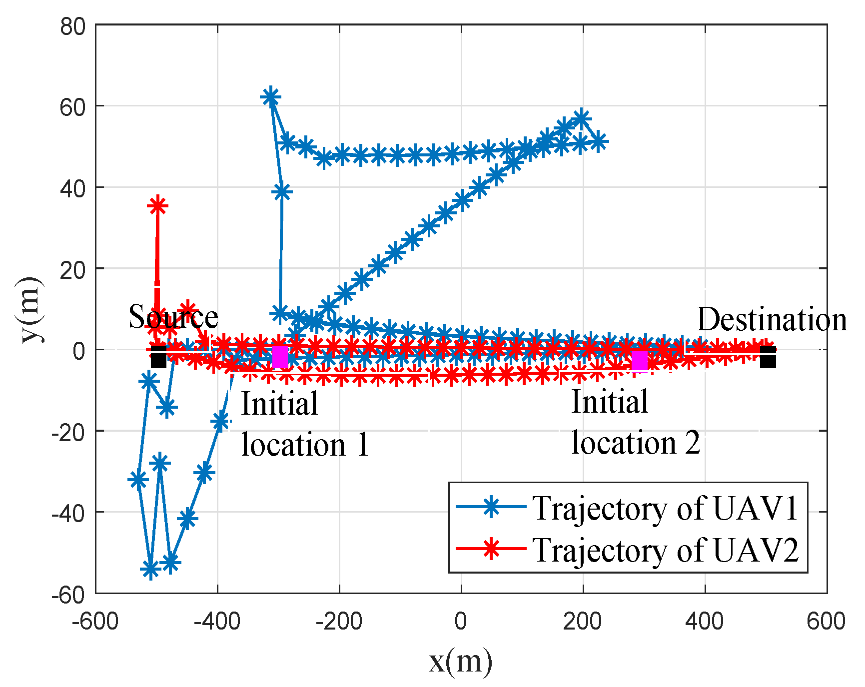
Figure 2 shows the UAVs optimization trajectories by the proposed algorithm for flight period T = 60 s. The initial locations of UAVs and ground nodes are marked with purple “ ” and black “ ”, respectively. In this figure, the asterisk indicates that the location of the UAV is sampled at every 0.5 s. The initial and final location of all UAVs satisfied a feasible constraint in (1), and all UAVs satisfied the minimum safety distance to avoid collision. From this figure, we can see the two UAVs tried to get close to their served ground nodes during every time slot under the flying constraints. Because the UAVs served the source or destination in different time slots, sometimes the trajectories of UAV1 and UAV2 may be a straight line from the source to the destination node.
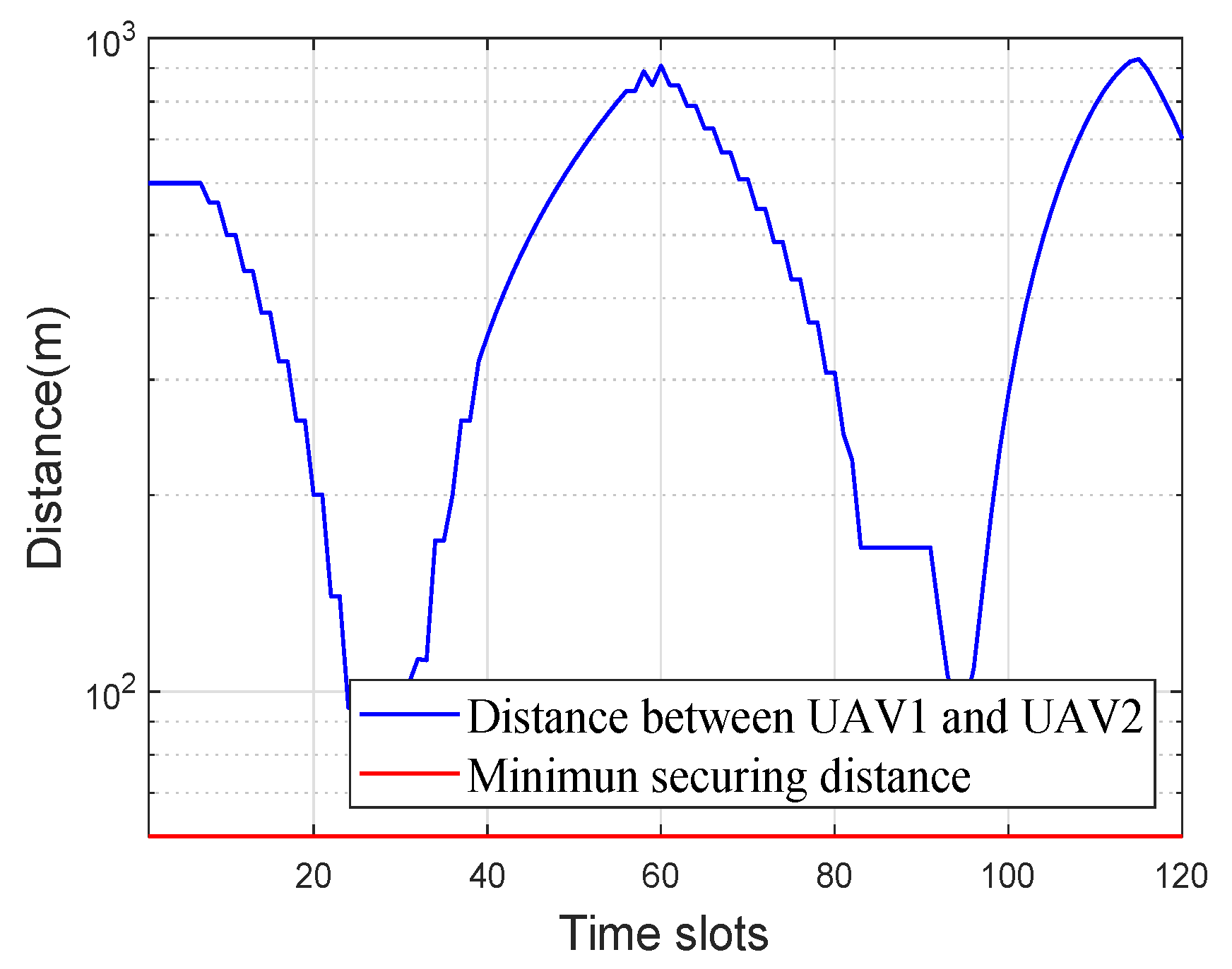
Then, in Figure 3, the flight security of the proposed algorithm is demonstrated for period time T = 60 s. It can be obviously observed that the distance between the two UAVs varied with time and always exceeded the minimum security distance. Therefore, the trajectories of the two UAVs satisfied the collision avoidance constraints in every time slot.
Figure 4 illustrates the average system throughput versus the different flight periods T of the proposed joint optimization algorithm. For comparison, we also simulated the following benchmark schemes:
  • No optimization: According to the CSI and buffer state, the system decided which UAV stored the data from the source and which UAV served the destination. The transmit power of UAVs p k n = p S = 0.1 W. A circular flight trajectory with radius of r = 300 m and the center of the flight trajectory above the middle of S and D were considered.
  • Only the relay selection and transmit power optimized: For a given trajectory, we only optimized the relay selection and transmit power via the proposed algorithm.
  • Only the trajectory optimized: For given relay selection and transmit power, we only optimized the trajectories via the proposed algorithm.
First, as expected, the average throughput could be increased by optimizing any variable (relay selection and transmit power and/or flight trajectory). Second, it is observed that the joint optimization algorithm we proposed could greatly increase the average throughput in comparison with optimizing a single variable. The results above further demonstrated that the trajectory optimization was more effective than optimizing relay selection and transmit power. Finally, it was found that the average throughput could be improved as the flight period increased with the joint optimization algorithm. In a word, the proposed algorithm could significantly improve the system performance in terms of throughput.
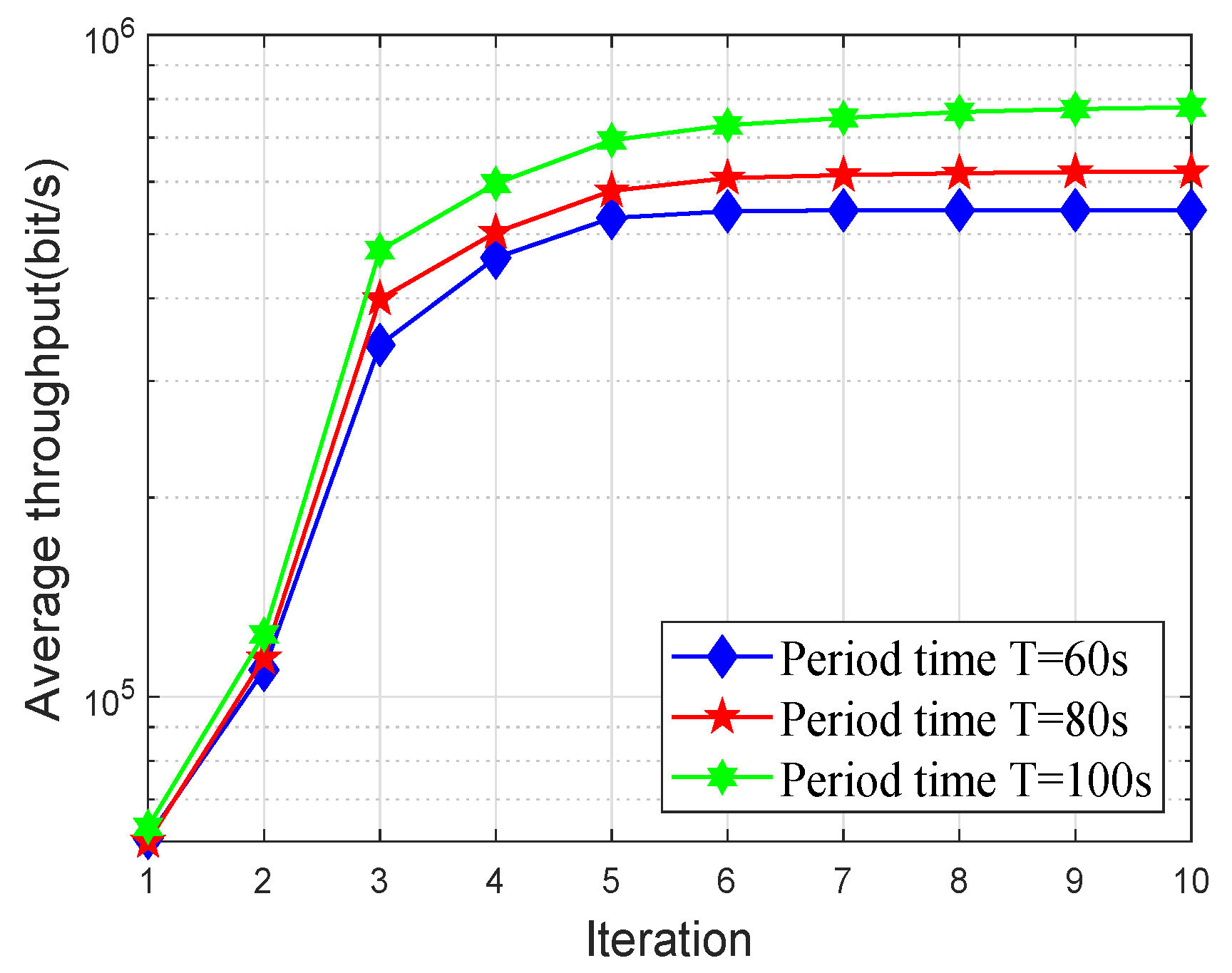
Next, we demonstrate the convergence behavior of Algorithm 1 in Figure 5. The average throughput of this network during different periods is illustrated. From this figure, it can be observed that with the number of iterations of the proposed algorithm increasing, the average throughput of this network gradually converged, and the convergence was achieved at about six iterations. Therefore, the curves satisfied our expectation and verified the effectiveness of the proposed algorithm in maximizing average throughput. Furthermore, it can be found that the system average throughput could be increased by prolonging the period time.

5. Conclusions

A buffer aided multi-UAV relaying network with joint trajectory and communication design was studied in this paper. Specifically, based on the information causality, aiming at maximizing the average throughput of the network, the relay selection, UAV transmit power, and UAV trajectory were jointly optimized. Since the maximization problem was a mixed integer non-convex problem, the problem was re-described and divided into iterations of the two sub-problems through the block coordinate descent and the successive convex optimization techniques. Finally, the convergence of the proposed algorithm was testified analytically. Numerical results demonstrated that Algorithm 1 could significantly improve the average throughput of the considered network. Furthermore, in this paper, we considered the transition of buffer states, and the proposed algorithm can avoid the collision of UAVs in multi-UAV relaying networks.

Author Contributions

D.C. and W.Y. conceived of the model; D.C. performed the simulation results and wrote the paper; and W.Y., G.X. provided some suggestions and revised the paper.

Funding

This work is supported by the National Natural Science Foundations of China under Grant 61771487 and Grant 61371122, and the Research Program of the National University of Defense Technology under Grant No.ZS18-02-04.

Conflicts of Interest

The authors declare no conflict of interest.

References

  1. Lyu, J.; Zeng, Y.; Zhang, R.; Lim, T.J. Placement Optimization of UAV-Mounted Mobile Base Stations. IEEE Commun. Lett. 2016, 21, 604–607. [Google Scholar] [CrossRef] [Green Version]
  2. Zeng, Y.; Zhang, R.; Lim, T.J. Throughput maximization for UAV-enabled mobile relaying systems. IEEE Trans. Commun. 2016, 64, 4983–4996. [Google Scholar] [CrossRef]
  3. Gupta, L.; Jain, R.; Vaszkun, G. Survey of important issues in UAV communication networks. IEEE Commun. Surv. Tutor. 2016, 18, 1123–1152. [Google Scholar] [CrossRef] [Green Version]
  4. Chen, M.C.; Pai, H.H.; Kung, H.T.; Dario, V. Maximizing throughput of UAV-relaying networks with the load-carry-and-deliver paradigm. In Proceedings of the IEEE Wireless Communications Networking Conference (WCNC), Kowloon, China, 11–15 March 2007; pp. 4417–4424. [Google Scholar]
  5. Zeng, Y.; Zhang, R.; Lim, T.J. Energy Minimization for Wireless Communication with Rotary-Wing UAV. IEEE Trans. Wirel. Commun. 2019, 18, 2329–2345. [Google Scholar] [CrossRef] [Green Version]
  6. Zhang, G.; Yan, H.; Zeng, Y.; Cui, M.; Liu, Y. Trajectory optimization and power allocation for multi-hop UAV relaying communications. IEEE Access 2018, 6, 48566–48576. [Google Scholar] [CrossRef]
  7. Nosratinia, A.; Hunter, T.E.; Hedayat, A. Cooperative communication in wireless networks. IEEE Commun. Surv. Tutor. 2014, 42, 74–80. [Google Scholar] [CrossRef]
  8. Nomikos, N.; Charalambous, T.; Vouyioukas, D.; Wichman, R.; Karagiannidis, G.K. Power Adaptation in Buffer-Aided Full-Duplex Relay Networks With Statistical CSI. IEEE Trans. Veh. Technol. 2018, 67, 7846–7850. [Google Scholar] [CrossRef]
  9. Mohammadmahdi, M.; Fernando, R.; Kwangcheng, C.; Sofie, P. Ultra reliable UAV communication using altitude and cooperation diversity. IEEE Trans. Commun. 2017, 66, 330–344. [Google Scholar]
  10. Li, Y.; Yang, D.; Xu, Y.; Xiao, L.; Chen, H. Throughput Maximization for UAV-Enabled Relaying in Wireless Powered Communication Networks. Sensors 2019, 19, 2989. [Google Scholar] [CrossRef] [Green Version]
  11. Li, A.; Wu, Q.; Zhang, R. UAV-enabled cooperative jamming for improving secrecy of ground wiretap channel. IEEE Wirel. Commun. Lett. 2018, 8, 181–184. [Google Scholar] [CrossRef] [Green Version]
  12. Hoon, L.; Subin, E.; Junhee, P.; Inkyu, L. UAV aided secure communications with cooperative jamming. IEEE Trans. Veh. Technol. 2018, 67, 9385–9392. [Google Scholar]
  13. Zhong, C.; Yao, J.; Xu, J. Secure UAV communication with cooperative jamming and trajectory control. IEEE Commun. Lett. 2018, 23, 286–289. [Google Scholar] [CrossRef] [Green Version]
  14. Wang, Q.; Chen, Z.; Mei, W.; Fang, J. Improving physical layer security using UAV-enabled mobile relaying. IEEE Wirel. Commun. Lett. 2017, 6, 310–313. [Google Scholar] [CrossRef]
  15. Shen, L.; Wang, N.; Ji, X.; Mu, X.; Cai, L. Iterative Trajectory Optimization for Physical-Layer Secure Buffer-Aided UAV Mobile Relaying. Sensors 2019, 19, 3442. [Google Scholar] [CrossRef] [PubMed] [Green Version]
  16. Juhyung, L.; Kihong, P.; Mohamedslim, A.; Youngchai, K. On the Throughput of Mixed FSO/RF UAV-Enabled Mobile Relaying Systems with a Buffer Constraint. In Proceedings of the IEEE International Conference on Communications (ICC), Shanghai, China, 20–24 May 2019. [Google Scholar]
  17. Jaroslav, H.; Pavel, P. Elevation Dependent Shadowing Model for Mobile Communications via High Altitude Platforms in Built-Up Areas. IEEE Trans. Antennas Propag. 2008, 56, 1078–1084. [Google Scholar]
  18. Liu, L.; Zhang, S.; Zhang, R. CoMP in the Sky: UAV Placement and Movement Optimization for Multi-User Communications. IEEE Trans. Commun. 2019, 18, 3192–3207. [Google Scholar] [CrossRef] [Green Version]
  19. You, C.; Zhang, R. 3D Trajectory Optimization in Rician Fading for UAV-Enabled Data Harvesting. IEEE Trans. Wirel. Commun. 2019, 6, 74648–74659. [Google Scholar] [CrossRef] [Green Version]
  20. Hong, M.; Razaviyayn, M.; Luo, Z.; Pang, J. A Unified Algorithmic Framework for Block-Structured Optimization Involving Big Data: With applications in machine learning and signal processing. IEEE Signal Process. Mag. 2015, 33, 57–77. [Google Scholar] [CrossRef] [Green Version]
  21. Khuwaja, A.; Chen, Y.; Zhao, N.; Alouini, M.S.; Dobbins, P. A survey of channel modeling for UAV communications. IEEE Commun. Surv. Tutor. 2018, 20, 280–2821. [Google Scholar] [CrossRef] [Green Version]
  22. Xu, Y.; Xiao, L.; Yang, D.; Wu, Q.; Cuthbert, L. Throughput Maximization in Multi-UAV Enabled Communication Systems with Difference Consideration. IEEE Access 2018, 6, 55291–55301. [Google Scholar] [CrossRef]
  23. Boyd, S.; Vandenberghe, L. Convex Optimization; Cambridge University Press: Cambridge, UK, 2004. [Google Scholar]
  24. Grant, M.; Boyd, S. CVX: MATLAB Software for Disciplined Convex Programming. 2016. Available online: http://cvxr.com/cvx (accessed on 3 November 2019).
  25. Zhang, G.; Wu, Q.; Cui, M.; Zhang, R. Securing UAV Communications via Joint Trajectory and Power Control. IEEE Trans. Wirel. Commun. 2019, 18, 1376–1389. [Google Scholar] [CrossRef] [Green Version]
  26. Wu, Q.; Zeng, Y.; Zhang, R. Joint trajectory and communication design for multi-UAV enabled wireless networks. IEEE Trans. Wirel. Commun. 2018, 17, 2109–2121. [Google Scholar] [CrossRef] [Green Version]
  27. Wang, H.; Ren, G.; Chen, J.; Ding, G.; Yang, Y. Unmanned aerial vehicle aided communications: Joint transmit power and trajectory optimization. IEEE Wirel. Commun. Lett. 2018, 7, 522–525. [Google Scholar] [CrossRef] [Green Version]
  28. Wang, H.; Wang, J.; Ding, G.; Chen, J.; Li, Y.; Han, Z. Spectrum sharing planning for full-duplex UAV relaying systems with underlaid D2D communications. IEEE J. Sel. Areas Commun. 2018, 36, 1986–1999. [Google Scholar] [CrossRef]
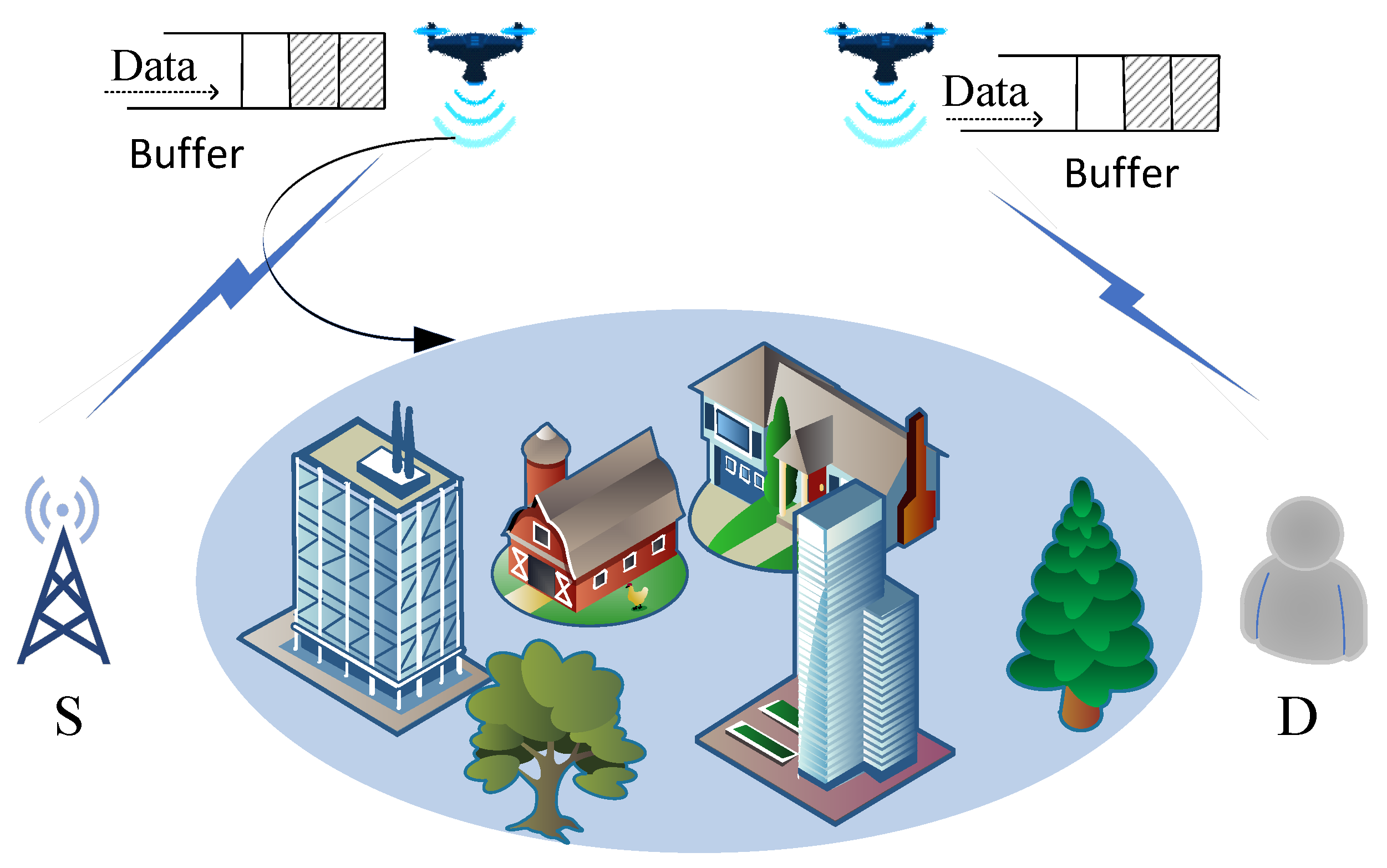
Figure 1. System model.
Applsci 09 05524 g001
Figure 2. Trajectories of the UAVs when T = 60 s.
Applsci 09 05524 g002
Figure 3. The distance between the two UAVs versus time with T = 60 s.
Applsci 09 05524 g003
Figure 4. Average throughput versus flight period T.
Applsci 09 05524 g004
Figure 5. Convergence behavior of Algorithm 1.
Applsci 09 05524 g005