Energy Efficiency Analysis of Fixed-Speed Pump Drives with Various Types of Motors

 ,
, 
 ,
,  and
and
Abstract
Featured Application
Abstract
1. Introduction
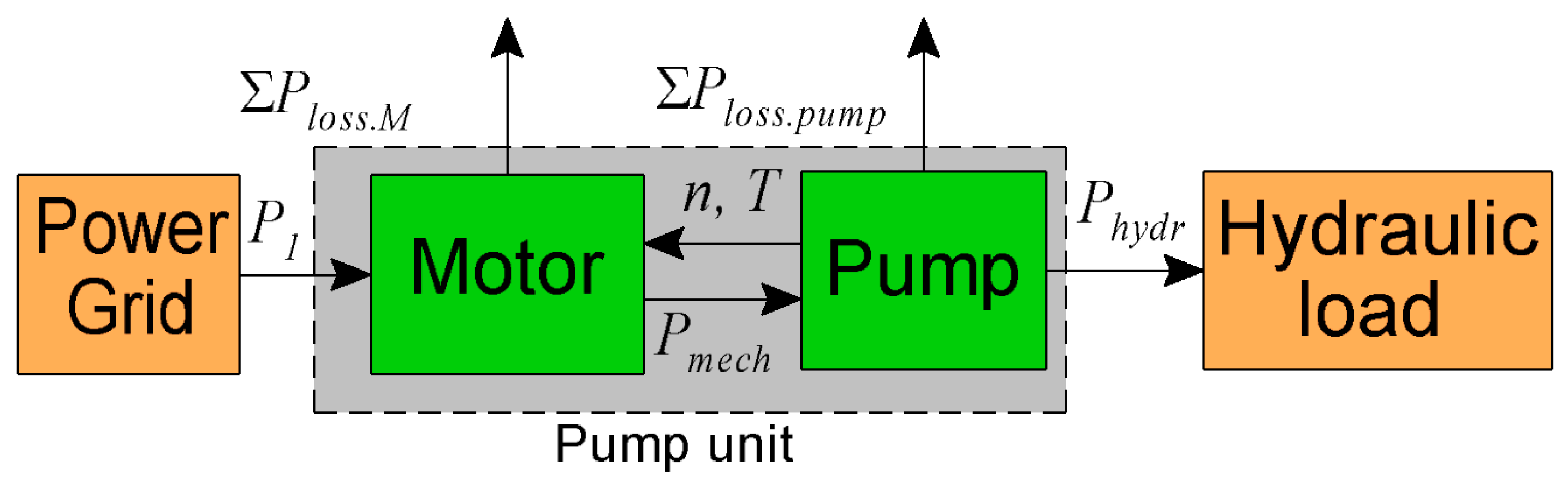
2. Characteristics of the Pump Unit and the Motors
3. Assessment of the Energy Consumption of the Pump Unit
4. Assessment of the Energy Efficiency Index of the Pump Unit
5. Conclusions
Author Contributions
Funding
Conflicts of Interest
References
- Almeida, A.; Ferreira, F.J.; Fong, J.; Fonseca, P. EuP Lot 11 Motors, Final report to the European Commission. 2008. Available online: https://circabc.europa.eu/sd/d/62415be2-3d5a-4b3f-b29a-d1760f4dc11a/Lot11%20Motors%201-8%20final%2028-04-08.pdf (accessed on 27 November 2019).
- Phillips, R.; Tieben, R. Improvement of Electric Motor Systems in Industry (IEMSI). In Proceedings of the Energy Efficiency in Motor Driven Systems (EEMODS ’17), Rome, Italy, 6–8 September 2017. [Google Scholar]
- European Commission. Study on Improving the Energy Efficiency of Pumps. 2001. Available online: http://www.jakob-albertsen.dk/komposit/Darmstadtrapport.pdf (accessed on 27 November 2019).
- Shankar, V.K.A.; Umashankar, S.; Paramasivam, S.; Hanigovszki, N. A comprehensive review on energy efficiency enhancement initiatives in centrifugal pumping system. Appl. Energy 2016, 181, 495–513. [Google Scholar] [CrossRef]
- European Commission Regulation (EC) No. 640/2009 Implementing Directive 2005/32/ EC of the European Parliament and of the Council with Regard to Ecodesign Requirements for Electric Motors, (2009), Amended by Commission Regulation (EU) No 4/2014 of January 6, 2014, Document 32014R0004. Available online: https://eur-lex.europa.eu/legal-content/EN/TXT/?uri=CELEX%3A32014R0004 (accessed on 27 November 2019).
- Rotating Electrical Machines—Part 30-1: Efficiency Classes of Line Operated AC Motors (IE Code); IEC 60034-30-1:2014; IEC: Geneva, Switzerland, 2014; Available online: https://webstore.iec.ch/publication/136 (accessed on 27 November 2019).
- De Almeida, A.; Fong, J.; Falkner, H. New European Ecodesign Regulation Proposal for Electric Motors and Drives. In Proceedings of the Energy Efficiency in Motor Driven Systems (EEMODS ’15), Helsinki, Finland, 15–17 September 2015. [Google Scholar]
- Stoffel, B. Assessing the Energy Efficiency of Pumps and Pump Units. In Background and Methodology; Elsevier: Amsterdam, The Netherlands, 2015. [Google Scholar]
- Gevorkov, L. Simulation and Experimental Study on Energy Management of Circulating Centrifugal Pumping Plants with Variable Speed Drives. Ph.D. Thesis, Tallinn University of Technology, Tallinn, Estonia, 2017. [Google Scholar]
- Shuvalova, J. Optimal Approximation of Input-Output Characteristics of Power Units and Plants. Ph.D. Thesis, Tallinn University of Technology, Tallinn, Estonia, 2004. [Google Scholar]
- Glover, A.; Lukaszczyk, M. Oversizing pump motors—The problems. World Pumps 2005, 2005, 36–38. [Google Scholar] [CrossRef]
- Safin, N.; Kazakbaev, V.; Prakht, V.; Dmitrievskii, V. Calculation of the Efficiency and Power Consumption of Induction IE2 and Synchronous Reluctance IE5 Electric Drives in the Pump Application Based on the Passport Specification According to the IEC 60034-30-2. In Proceedings of the 25th International Workshop on Electric Drives: Optimization in Control of Electric Drives (IWED), Moscow, Russia, 31 January—2 February 2018. [Google Scholar] [CrossRef]
- Kazakbaev, V.; Prakht, V.; Dmitrievskii, V.; Ibrahim, M.; Oshurbekov, S.; Sarapulov, S. Efficiency Analysis of Low Electric Power Drives Employing Induction and Synchronous Reluctance Motors in Pump Applications. Energies 2019, 12, 1144. [Google Scholar] [CrossRef]
- Mutize, C.; Wang, R. Performance comparison of an induction machine and line-start PM motor for cooling fan applications. Proc. SAUPEC 2013. [Google Scholar] [CrossRef]
- Li, J.; Song, J.; Cho, Y. High Performance Line Start Permanent Magnet Synchronous Motor for Pumping System. IEEE Int. Symp. Ind. Electron. 2010. [Google Scholar] [CrossRef]
- Kahrisangi, M.G.; Isfahani, A.H.; Vaez-Zadeh, S.; Sebdani, M.R. Line-start permanent magnet synchronous motors versus induction motors: A comparative study. Front. Electr. Electron. Eng. 2012, 2095–2732. [Google Scholar] [CrossRef]
- NM, NMS. Close Coupled Centrifugal Pumps with Flanged Connections; Catalogue; Calpeda. 2018. Available online: https://www.calpeda.com/system/pdf/catalogue_en_50hz.pdf (accessed on 27 November 2019).
- Catalogue of Super Premium Efficiency SynchroVERT LSPM Motors. Available online: https://www.bharatbijlee.com/media/14228/synchrovert_catalogue.pdf (accessed on 27 November 2019).
- Wquattro 2.2 kW 4P 100L 3Ph 230/400 V 50 Hz IC411-TEFC-B3T. Product Details. Available online: https://www.weg.net/catalog/weg/RU/en/Electric-Motors/Special-Application-Motors/Permanent-Magnet-Motors/Line-Start-PM-Motors/Wquattro-2-2-kW-4P-100L-3Ph-230-400-V-50-Hz-IC411---TEFC---B3T/p/13009386 (accessed on 27 November 2019).
- Addendum to the Operating Instructions: AC Motors DR.71.J-DR.100.J with LSPM Technology, 21281793/EN, 09/2014, SEW Eurodrive. Available online: https://download.sew-eurodrive.com/download/pdf/21343799.pdf (accessed on 27 November 2019).
- Catalog Siemens D81.1 Simotics GP, SD, XP, DP Low-Voltage Motors, 05/2018. Available online: https://support.industry.siemens.com/cs/attachments/109749197/Motors-D81.1-complete-English-07-2019.pdf?download=true (accessed on 27 November 2019).
- W22 Super Premium Efficiency 3 HP 4P 182/4T 3Ph 208-230/460//380 V 60 Hz IC411-TEFC-Foot-Mounted. Product Details. Available online: https://www.weg.net/catalog/weg/MV/en/Electric-Motors/Low-Voltage-NEMA-Motors/General-Purpose-ODP-TEFC/Cast-Iron-TEFC-General-Purpose/W22-Super-Premium-Efficiency/W22-Super-Premium-Efficiency-3-HP-4P-182-4T-3Ph-208-230-460-380-V-60-Hz-IC411---TEFC---Foot-mounted/p/12792146 (accessed on 27 November 2019).
- Multimounting IE3 2.2 kW 4P 100L 3Ph 220-240/380-415//460 V 50 Hz IC411-TEFC-B3T. Product Details. Available online: https://www.weg.net/catalog/weg/RU/en/Electric-Motors/Low-Voltage-IEC-Motors/General-Purpose-ODP-TEFC/Aluminum-TEFC-General-Purpose/Aluminium-TEFC-General-Purpose/Multimounting-IE3/Multimounting-IE3-2-2-kW-4P-100L-3Ph-220-240-380-415-460-V-50-Hz-IC411---TEFC---B3T/p/12397774 (accessed on 27 November 2019).
- Catalog ABB—Low Voltage General Performance Motors. June 2018. Available online: https://library.e.abb.com/public/00389a1977844886b7e3e7560a6c22bf/9AKK105789%20EN%2006-2018%20General%20Perf.pdf (accessed on 27 November 2019).
- Commission Regulation (EC) No 641/2009 of July 22, 2009 implementing Directive 2005/32/EC of the European Parliament and of the Council with regard to ecodesign requirements for glandless standalone circulators and glandless circulators integrated in products, amended by Commission Regulation (EU) No 622/2012 of July 11, 2012, Document 02009R0641-20170109. Available online: https://eur-lex.europa.eu/legal-content/EN/TXT/?uri=CELEX%3A02009R0641-20170109 (accessed on 27 November 2019).
- Ferreira, F.J.T.E.; de Almeida, A.T. Energy Savings Potential Associated with Stator Winding Connection Mode Change in Induction Motors. In Proceedings of the XXII International Conference on Electrical Machines (ICEM), Lausanne, Switzerland, 04–07 September 2016; pp. 2775–2783. [Google Scholar]
- Eurostat Data for the Industrial Consumers in Germany. Available online: http://ec.europa.eu/eurostat/statistics-explained/index.php/Electricity_price_statistics#Electricity_prices_for_industrial_consumers (accessed on 27 November 2019).
- Pump Life Cycle Costs: A Guide to LCC Analysis for Pumping Systems, Executive Summary. Hydraulic Institute (Parsippany, NJ); Europump (Brussels, Belgium); Office of Industrial Technologies Energy Efficiency and Renewable Energy U.S. Department of Energy (Washington, DC). January 2001, pp. 1–19. Available online: https://searchworks.stanford.edu/view/4676735 (accessed on 27 November 2019).
- Waghmode, L.; Sahasrabudhe, A. A comparative study of life cycle cost analysis of pumps. In Proceedings of the ASME 2010 International Design Engineering Technical Conferences and Computers and Information in Engineering Conference (ASME 2010), Montreal, QC, Canada, 15–18 August 2010; Volume 6, pp. 491–500. [Google Scholar]
- Rotating Electrical Machines—Part 30-2: Efficiency Classes of Variable Speed AC Motors (IE-Code); IEC TS 60034-30-2:2016; IEC: Geneva, Switzerland, 2016; Available online: https://webstore.iec.ch/publication/30830 (accessed on 27 November 2019).
- Rotating Electrical Machines—Part 30-2: Efficiency Classes of Variable Speed AC Motors (IE-Code); Document 2/1709/NP; Standard draft; IEC: Geneva, Switzerland, 2013; Available online: https://www.iec.ch/dyn/www/f?p=103:52:0::::FSP_ORG_ID,FSP_DOC_ID,FSP_DOC_PIECE_ID:1221,151336,279593 (accessed on 27 November 2019).
- De Lima, W.I.B. Rare Earth Industry; Elsevier: Amsterdam, The Netherlands, 2015. [Google Scholar]
- Dent, P. Rare earth elements and permanent magnets. J. Appl. Phys. 2012, 111. [Google Scholar] [CrossRef]
- Goss, J.; Popescu, M.; Staton, D. A Comparison of an Interior Permanent Magnet and Copper Rotor Induction Motor in a Hybrid Electric Vehicle Application. In Proceedings of the IEEE International Electric Machines & Drives Conference, EMDC, Chicago, IL, USA, 12–15 May 2013. [Google Scholar]
- Ismagilov, F.R.; Vavilov, V.E.; Gusakov, D.V. Line-Start Permanent Magnet Synchronous Motor for Aerospace Application. In Proceedings of the IEEE International Conference on Electrical Systems for Aircraft, Railway, Ship Propulsion and Road Vehicles and International Transportation Electrification Conference, ESARS-ITEC, Nottingham, UK, 7–9 November 2018. [Google Scholar] [CrossRef]
- Sorgdrager, J.; Wang, R.; Grobler, A.J. Multi-Objective Design of a Line-Start PM Motor Using the Taguchi Method. IEEE Trans. Ind. Appl. 2018, 54, 4167–4176. [Google Scholar] [CrossRef]
- Kurihara, K.; Rahman, M.A. High-Efficiency Line-Start Interior Permanent-Magnet Synchronous Motors. IEEE Trans. Ind. Appl. 2004, 40, 789–796. [Google Scholar] [CrossRef]
- Azari, M.N.; Mirsalim, M. Line-start permanent-magnet motor synchronisation capability improvement using slotted solid rotor. IET Electr. Power Appl. 2013, 7. [Google Scholar] [CrossRef]
- Ferreira, F.J.T.; Leprettre, B.; De Almeida, A.T. Comparison of protection requirements in IE2-IE3-and IE4-class motors. IEEE Trans. Ind. Appl. 2016, 52, 3603–3610. [Google Scholar] [CrossRef]
- Commission Regulation (EU) No 547/2012 of June 25, 2012 Implementing Directive 2009/125/EC of the European Parliament and of the Council with Regard to Ecodesign Requirements for Water Pumps. Available online: https://eur-lex.europa.eu/legal-content/EN/TXT/?uri=CELEX%3A32012R0547 (accessed on 27 November 2019).
- Extended Product Approach for Pumps, Copyright © 2014 by Europump. Published by Europump. Available online: http://europump.net/uploads/Extended%20Product%20Approach%20for%20Pumps%20-%20A%20Europump%20guide%20(27OCT2014).pdf (accessed on 27 November 2019).
- Lang, S.; Ludwig, G.; Pelz, P.F.; Stoffel, B. General Methodologies of Determining the Energy Efficiency Index of Pump Units in the Frame of the Extended Product Approach; EEMODS: Rio de Janeiro, Brazil, 2013. [Google Scholar]


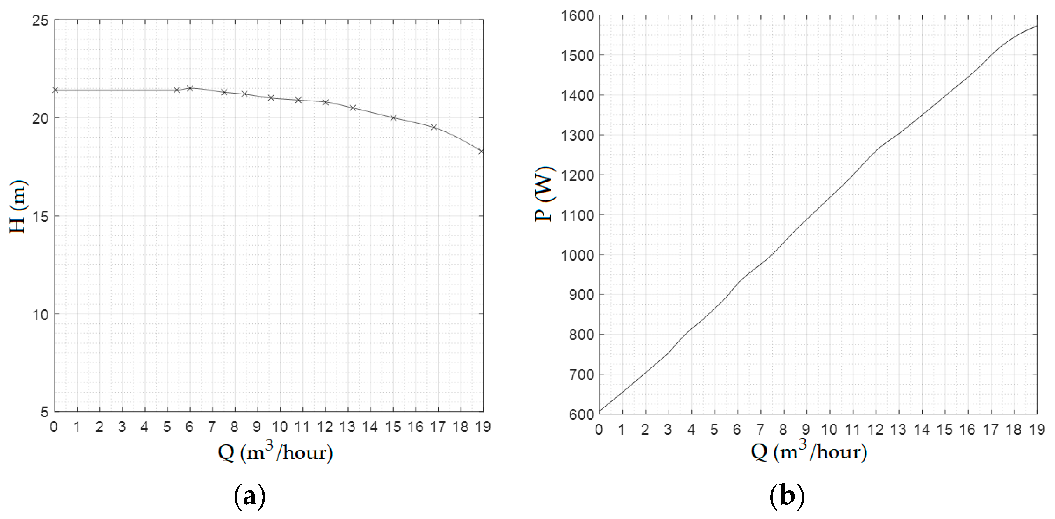
| Parameter | Type | PRATE (W) | n (rpm) | QBEP (m3/h) | HBEP (m) | Efficiency (%) |
|---|---|---|---|---|---|---|
| Value | NM4 40/25B | 2200 | 1450 | 19 | 17.8 | 60 |
| m | Type of Motor | Efficiency Class | Efficiency (%) at the Various Loads | ||
|---|---|---|---|---|---|
| 50% | 75% | 100% | |||
| 1 | LSPMSM SEW DRU J | IE4 | 88.0 | 90.5 | 91.2 |
| 2 | LSPMSM SynchroVERT | IE4 | 88.6 | 89.4 | 89.5 |
| 3 | LSPMSM WEG WQuattro | IE4 | 86.0 | 89.0 | 90.2 |
| 4 | IM Siemens 1LE1004 | IE4 | 88.3 | 89.6 | 89.5 |
| 5 | IM WEG W22 | IE4 | 88.5 | 89.5 | 89.5 |
| 6 | IM Siemens 1LE1003 | IE3 | 86.4 | 87.3 | 86.7 |
| 7 | IM WEG W21 | IE3 | 86.5 | 87.0 | 87.0 |
| 8 | IM ABB M3BP | IE3 | 85.1 | 86.9 | 86.7 |
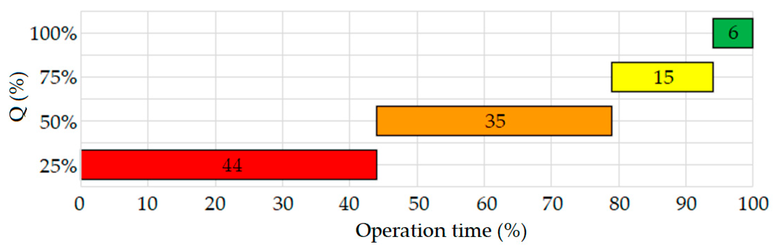
| Mode Number i | 1 | 2 | 3 | 4 |
|---|---|---|---|---|
| Operation time (%) | 44 | 35 | 15 | 6 |
| Operation time (h/day) | 10.56 | 8.4 | 3.6 | 1.44 |
| Qi (%) | 25 | 50 | 75 | 100 |
| Qi (m3/h) | 4.75 | 9.50 | 14.25 | 19.00 |
| Hpump.i (%) | 120 | 118 | 113 | 100 |
| Hpump.i (m) | 21.4 | 21.0 | 20.2 | 17.8 |
| Pmech.i (W) | 851 | 1116 | 1361 | 1573 |
| Pmech.i (%) | 38.7 | 50.7 | 61.9 | 71.5 |
| Efficiency ηM.i.m (%) | ||||
| 1. LSPMSM SEW DRU J | 85.5 | 88.1 | 89.5 | 90.3 |
| 2. LSPMSM SynchroVERT | 87.7 | 88.6 | 89.1 | 89.3 |
| 3. LSPMSM WEG WQuattro | 83.3 | 86.1 | 87.8 | 88.7 |
| 4. IM Siemens 1LE1004 | 86.7 | 88.4 | 89.2 | 89.5 |
| 5. IM WEG W22 | 85.8 | 88.2 | 89.3 | 89.7 |
| 6. IM Siemens 1LE1003 | 84.9 | 86.5 | 87.1 | 87.3 |
| 7. IM WEG W21 | 84.8 | 86.3 | 86.9 | 87.2 |
| 8. IM ABB M3BP | 82.7 | 85.2 | 86.3 | 86.8 |
| Type of Motor | 1 | 2 | 3 | 4 |
|---|---|---|---|---|
| 1. LSPMSM SEW DRU J | 996.2 | 1266.1 | 1520.3 | 1742.3 |
| 2. LSPMSM Synchro-VERT | 971.3 | 1258.6 | 1527.4 | 1760.8 |
| 3. LSPMSM WEG WQuattro | 1022.6 | 1295.2 | 1550.9 | 1773.1 |
| 4. IM Siemens 1LE1004 | 982.2 | 1262.0 | 1526.3 | 1757.5 |
| 5. IM WEG W22 | 992.9 | 1264.8 | 1524.4 | 1753.8 |
| 6. IM Siemens 1LE1003 | 1003.1 | 1289.9 | 1562.5 | 1802.5 |
| 7. IM WEG W21 | 1004.4 | 1293.1 | 1566.0 | 1805.0 |
| 8. IM ABB M3BP | 1029.4 | 1309.4 | 1576.4 | 1812.2 |
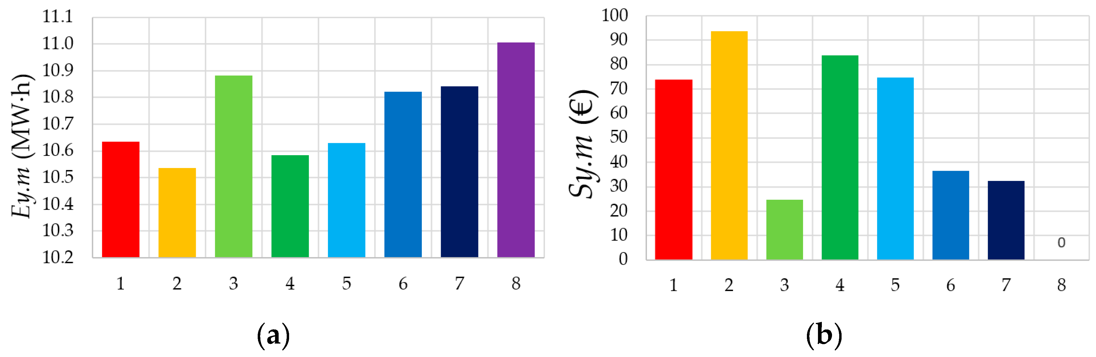
| Type of Motor | Ed.m (kW·h) | Ey.m (kW·h) | Cy.m (€) | CLCCen.m (k€) | Sy.m (€) |
|---|---|---|---|---|---|
| 1. LSPMSM SEW DRU J | 29.1 | 10,635 | 2113.1 | 34.55 | 73.8 |
| 2. LSPMSM SynchroVERT | 28.9 | 10,535 | 2093.3 | 34.23 | 93.6 |
| 3. LSPMSM WEG WQuattro | 29.8 | 10,882 | 2162.3 | 35.36 | 24.6 |
| 4. IM Siemens 1LE1004 | 29.0 | 10,585 | 2103.1 | 34.39 | 83.8 |
| 5. IM WEG W22 | 29.1 | 10,630 | 2112.1 | 34.54 | 74.8 |
| 6. IM Siemens 1LE1003 | 29.6 | 10,822 | 2150.3 | 35.16 | 36.6 |
| 7. IM WEG W21 | 29.7 | 10,843 | 2154.4 | 35.23 | 32.5 |
| 8. IM ABB M3BP | 30.2 | 11,006 | 2186.9 | 35.76 | 0 |
| m | Type of Motor | P1.avg (W) | EEI |
|---|---|---|---|
| 1 | LSPMSM SEW DRU J | 1214 | 0.5786 |
| 2 | LSPMSM SynchroVERT | 1203 | 0.5732 |
| 3 | LSPMSM WEG WQuattro | 1242 | 0.5921 |
| 4 | IM Siemens 1LE1004 | 1208 | 0.5759 |
| 5 | IM WEG W22 | 1213 | 0.5784 |
| 6 | IM Siemens 1LE1003 | 1235 | 0.5888 |
| 7 | IM WEG W21 | 1238 | 0.5899 |
| 8 | IM ABB M3BP | 1256 | 0.5988 |
© 2019 by the authors. Licensee MDPI, Basel, Switzerland. This article is an open access article distributed under the terms and conditions of the Creative Commons Attribution (CC BY) license (http://creativecommons.org/licenses/by/4.0/).
Share and Cite
Goman, V.; Oshurbekov, S.; Kazakbaev, V.; Prakht, V.; Dmitrievskii, V. Energy Efficiency Analysis of Fixed-Speed Pump Drives with Various Types of Motors. Appl. Sci. 2019, 9, 5295. https://doi.org/10.3390/app9245295
Goman V, Oshurbekov S, Kazakbaev V, Prakht V, Dmitrievskii V. Energy Efficiency Analysis of Fixed-Speed Pump Drives with Various Types of Motors. Applied Sciences. 2019; 9(24):5295. https://doi.org/10.3390/app9245295
Chicago/Turabian StyleGoman, Victor, Safarbek Oshurbekov, Vadim Kazakbaev, Vladimir Prakht, and Vladimir Dmitrievskii. 2019. "Energy Efficiency Analysis of Fixed-Speed Pump Drives with Various Types of Motors" Applied Sciences 9, no. 24: 5295. https://doi.org/10.3390/app9245295
APA StyleGoman, V., Oshurbekov, S., Kazakbaev, V., Prakht, V., & Dmitrievskii, V. (2019). Energy Efficiency Analysis of Fixed-Speed Pump Drives with Various Types of Motors. Applied Sciences, 9(24), 5295. https://doi.org/10.3390/app9245295