A High Peak Power and High Beam Quality Sub-Nanosecond Nd:YVO4 Laser System at 1 kHz Repetition Rate without SRS Process

 ,
,
Abstract
1. Introduction
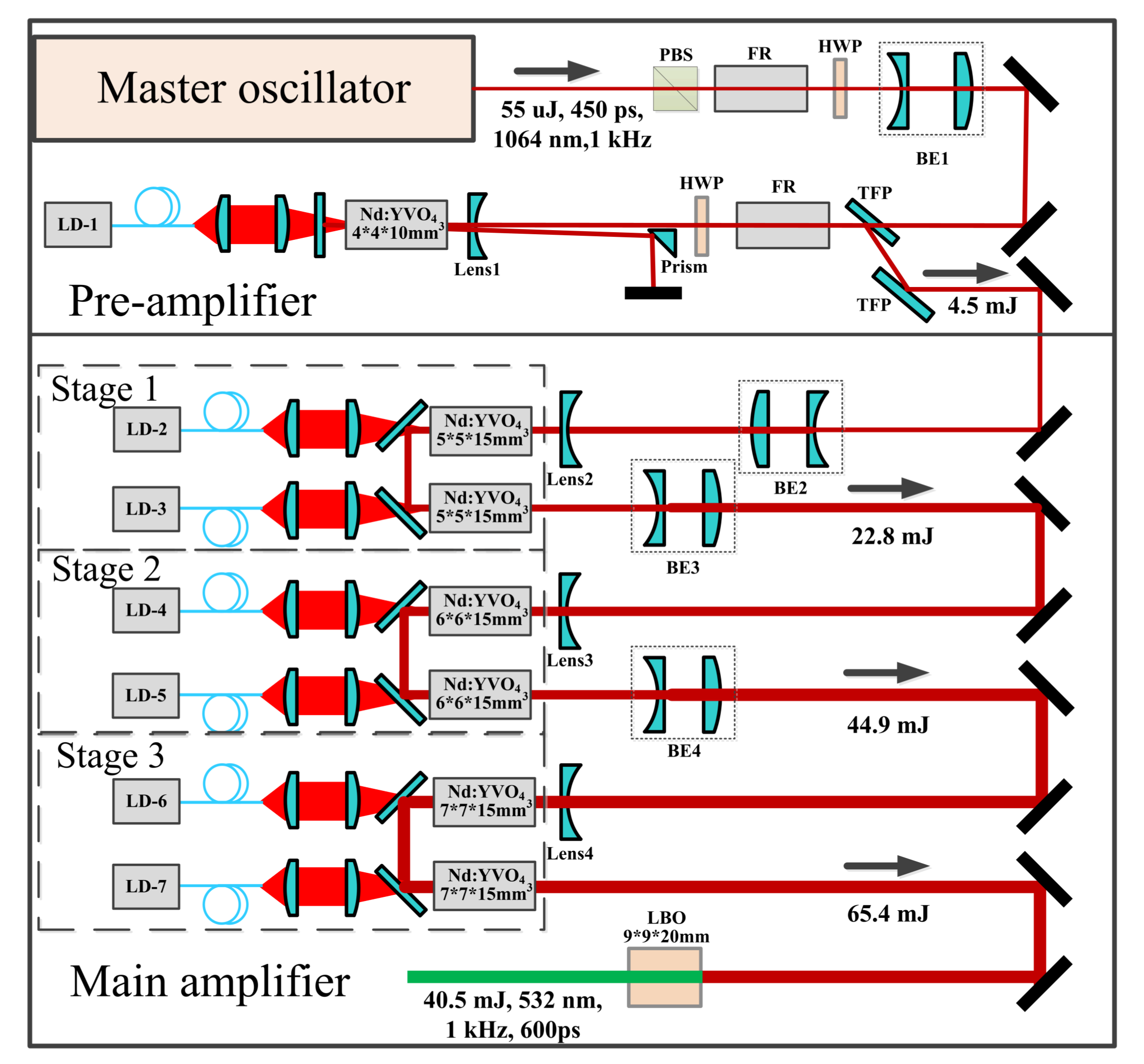
2. Experiment Setup
3. Experimental Results and Discussions
3.1. Pre-Amplifier
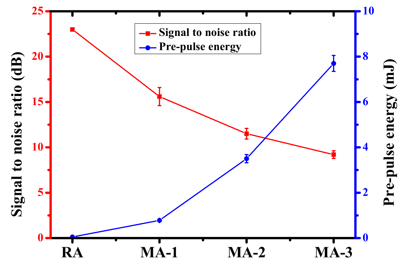
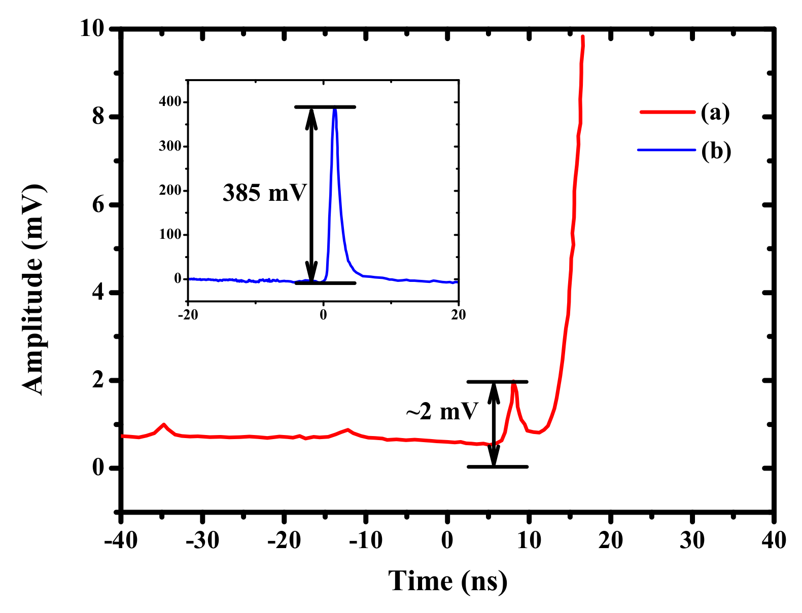
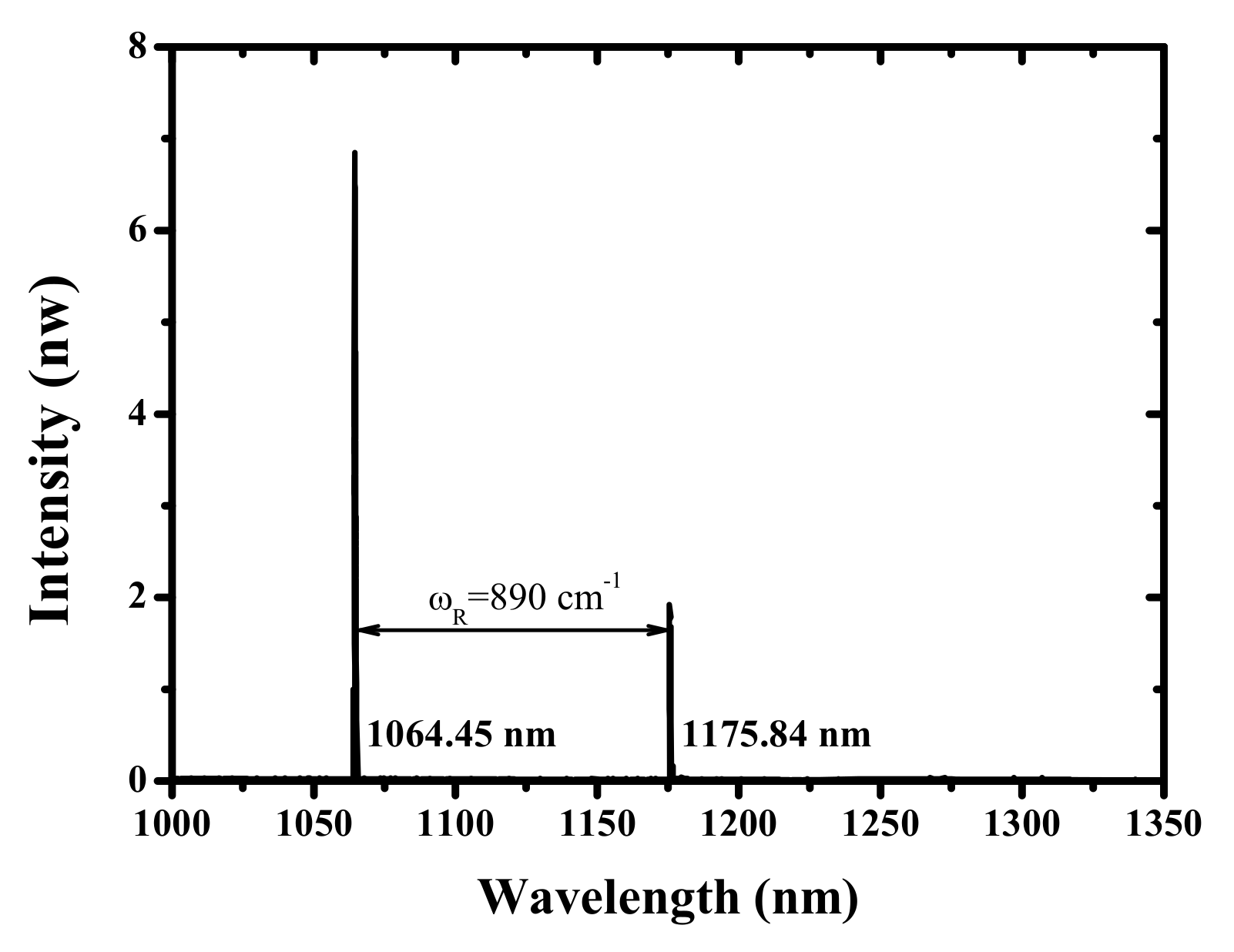
3.2. Main Amplifier and Suppression of SRS effect
3.3. Conclusions
Author Contributions
Acknowledgments
Conflicts of Interest
Abbreviations
| MDPI | Multidisciplinary Digital Publishing Institute |
| DOAJ | Directory of open access journals |
| TLA | Three letter acronym |
| LD | linear dichroism |
References
- Ostermeyer, M.; Kappe, P.; Menzel, R.; Wulfmeyer, V. Diode-pumped Nd: YAG master oscillator power amplifier with high pulse energy, excellent beam quality, and frequency-stabilized master oscillator as a basis for a next-generation lidar system. Appl. Opt. 2005, 44, 582–590. [Google Scholar] [CrossRef] [PubMed]
- Zhai, D.; Li, Y.; Xu, R.; Fu, H.; Zhang, H.; Li, Z.; Xiong, Y. Design and Realization of Single Telescope Transmitting and Twin Receiving Laser Ranging System at Yunnan Observatories. Astron. Res. Technol. 2017, 14, 310–316. [Google Scholar]
- O’Neill, W.; Li, K. High-quality micromachining of silicon at 1064 nm using a high-brightness MOPA-based 20-W Yb fiber laser. IEEE J. Sel. Top. Quantum Electron. 2009, 15, 462–470. [Google Scholar] [CrossRef]
- Deyra, L.; Martial, I.; Balembois, F.; Diderjean, J.; Georges, P. Megawatt peak power, 1 kHz, 266 nm sub nanosecond laser source based on single-crystal fiber amplifier. Appl. Phys. B 2013, 111, 573–576. [Google Scholar] [CrossRef]
- Major, A.; Sukhoy, K.; Zhao, H.; Lima, I. Green sub-nanosecond microchip laser based on BiBO crystals. Laser Phys. 2011, 21, 57–60. [Google Scholar] [CrossRef]
- Petrov, V.; Marchev, G.; Schunemann, P.G.; Tyazhev, A.; Zawilski, K.T.; Pollak, T.M. Sub-nanosecond, 1-kHz, temperature-tuned, non-critical mid-IR OPO based on CdSiP 2 crystal pumped at 1064 nm. In Proceedings of the Conference on Lasers and Electro-Optics, San Jose, CA, USA, 16–21 May 2010. [Google Scholar]
- Chuchumishev, D.; Gaydardzhiev, A.; Fiebig, T.; Buchvarov, I. 0.7 mJ, 0.5 kHz Mid-IR Tunable PPSLT Based OPO Pumped at 1064 nm. In Proceedings of the Advanced Solid-State Photonics, San Diego, CA, USA, 29 January–1 February 2012. [Google Scholar]
- Marchev, G.; Petrov, V.; Tyazhev, A.; Pasiskevicius, V.; Thilmann, N.; Laurell, F.; Buchvarov, I. Sub-nanosecond, 1-kHz, low-threshold, non-critical OPO based on periodically-poled KTP crystal pumped at 1064 nm. In Nonlinear Frequency Generation and Conversion: Materials, Devices, and Applications XI; International Society for Optics and Photonics: San Francisco, CA, USA, 15 February 2012; Volume 8240, p. 82400D. [Google Scholar]
- Chuchumishev, D.; Gaydardzhiev, A.; Richter, C.; Buchvarov, I. 5 mJ, sub-nanosecond PPSLT OPA at 0.5 kHz, tunable in the water absorption band at 3 microns. In Proceedings of the IEEE 2013 Conferenceon and International Quantum Electronics Conference Lasers and Electro-Optics Europe (CLEO EUROPE/IQEC), Munich, Germany, 12–16 May 2013. [Google Scholar]
- Chuchumishev, D.; Gaydardzhiev, A.; Fiebig, T.; Buchvarov, I. Subnanosecond, mid-IR, 0.5 kHz periodically poled stoichiometric LiTaO 3 optical parametric oscillator with over 1 W average power. Opt. Lett. 2013, 38, 3347–3349. [Google Scholar] [CrossRef]
- Kyusho, Y.; Arai, M.; Mukaihara, K.; Yamane, T.; Hotta, K.; Kuwano, Y.; Saito, S. High-energy subnanosecond compact laser system with diode-pumped, Q-switched Nd: YVO4 laser. In Proceedings of the Advanced Solid State Lasers, San Francisco, CA, USA, 31 January 1996. [Google Scholar]
- Gaydardzhiev, A.; Trifonov, A.; Fiebig, T.; Buchvarov, I. High-power diode pumped Nd: YAG master oscillator power amplifier system. In International Conference on Ultrafast and Nonlinear Optics 2009; International Society for Optics and Photonics: Bourgas, Bulgaria, 2009; Volume 7501, p. 750105. [Google Scholar]
- Yu, A.; Krainak, M.; Betin, A.; Hendry, D.; Hendry, B.; Sotelo, C. Highly Efficient Yb: YAG Master Oscillator Power Amplifier Laser Transmitter for Lidar Applications. In Proceedings of the Conference on Lasers and Electro-Optics 2012, San Jose, CA, USA, 6–11 May 2012. [Google Scholar]
- Druon, F.; Balembois, F.; Georges, P.; Brun, A. High-repetition-rate 300-ps pulsed ultraviolet source with a passively Q-switched microchip laser and a multipass amplifier. Opt. Lett. 1999, 24, 499–501. [Google Scholar] [CrossRef]
- Höiminger, C.; Zhang, G.; Moser, M.; Keller, U.; Johannsen, I.; Giesen, A. Diode-pumped thin disc Yb:YAG regenerative amplifier. In Proceedings of the Advanced Solid State Lasers, Coeur d’Alene, ID, USA, 2 February 1998. [Google Scholar]
- Kaksis, E.; Andriukaitis, G.; Flöry, T.; Pugžlys, A.; Baltuška, A. 30-mJ 200-fs cw-Pumped Yb:CaF2 Regenerative Amplifier. In Proceedings of the Conference on Lasers and Electro-Optics, San Jose, CA, USA, 5–10 June 2016. [Google Scholar]
- Agnesi, A.; Dallocchio, P.; Pirzio, F.; Reali, G. Sub-nanosecond single-frequency 10-kHz diode-pumped MOPA laser. Appl. Phys. B 2010, 98, 737–741. [Google Scholar] [CrossRef]
- Jelínek, M.; Kubeček, V.; Čech, M.; Hiršl, P. 0.8 mJ quasi-continuously pumped sub-nanosecond highly doped Nd: YAG oscillator-amplifier laser system in bounce geometry. Laser Phys. Lett. 2011, 8, 205. [Google Scholar] [CrossRef]
- Michailovas, K.; Smilgevičius, V.; Michailovas, A. High average power effective pump source at 1 kHz repetition rate for OPCPA system. Lith. J. Phys. 2014, 54. [Google Scholar] [CrossRef]
- Liu, J.; Wang, W.; Wang, Z.; Lv, Z.; Zhang, Z.; Wei, Z. Diode-pumped high energy and high average power all-solid-state picosecond amplifier systems. Appl. Sci. 2015, 5, 1590–1602. [Google Scholar] [CrossRef]
- Oreshkov, B.; Chuchumishev, D.; Iliev, H.; Trifonov, A.; Fiebig, T.; Richter, C.P.; Buchvarov, I. 52-mJ, kHz-Nd: YAG laser with diffraction limited output. In Proceedings of the IEEE 2014 Conference on Lasers and Electro-Optics (CLEO), San Jose, CA, USA, 8–13 June 2014; pp. 1–2. [Google Scholar]
- Chuchumishev, D.; Gaydardzhiev, A.; Trifonov, A.; Buchvarov, I.C. 13-mJ, single frequency, sub-nanosecond Nd: YAG laser at kHz repetition rate with near diffraction limited beam quality. In Proceedings of the CLEO: Applications and Technology, San Jose, CA, USA, 6–11 May 2012. [Google Scholar]
- Honig, J.; Halpin, J.; Browning, D.; Crane, J.; Hackel, R.; Henesian, M.; Peterson, J.; Ravizza, D.; Wennberg, T.; Rieger, H.; et al. Diode-pumped Nd: YAG laser with 38 W average power and user-selectable, flat-in-time subnanosecond pulses. Appl. Opt. 2007, 46, 3269–3275. [Google Scholar] [CrossRef] [PubMed]
- Dong, J.; Liu, X.S.; Peng, C.; Liu, Y.Q.; Wang, Z.Y. High Power Diode-Side-Pumped Q-Switched Nd: YAG Solid-State Laser with a Thermoelectric Cooler. Appl. Sci. 2015, 5, 1837–1845. [Google Scholar] [CrossRef]
- Bai, Z.A.; Fan, Z.W.; Bai, Z.X.; Lian, F.Q.; Kang, Z.J.; Lin, W.R. Optical fiber pumped high repetition rate and high power Nd: YVO4 picosecond regenerative amplifier. Appl. Sci. 2015, 5, 359–366. [Google Scholar] [CrossRef]
- Shen, Y.; Zhang, W.; Gong, M.; Meng, Y.; Wang, Y.; Fu, X. Four-Dimensional Thermal Analysis of 888 nm Pumped Nd: YVO4 Dual-Rod Acousto-Optic Q-Switched Laser. Appl. Sci. 2017, 7, 470. [Google Scholar] [CrossRef]
- Bai, Z.; Bai, Z.; Kang, Z.; Lian, F.; Lin, W.; Fan, Z. Non-Pulse-Leakage 100-kHz Level, High Beam Quality Industrial Grade Nd: YVO4 Picosecond Amplifier. Appl. Sci. 2017, 7, 615. [Google Scholar] [CrossRef]
- Li, R.; Bauer, R.; Lubeigt, W. Continuous-Wave Nd:YVO4 self-Raman lasers operating at 1109 nm, 1158 nm and 1231 nm. Opt. Express 2013, 21, 17745–17750. [Google Scholar] [CrossRef]
- Huang, G.; Yu, Y.; Xie, X.; Zhang, Y.; Du, C. Diode-pumped simultaneously Q-switched and mode-locked YVO4/Nd:YVO4/YVO4 crystal self-Raman first-Stokes laser. Opt. Express 2013, 21, 19723–19731. [Google Scholar] [CrossRef]
- Li, R.; Griffith, M.; Laycock, L.; Lubeigt, W. Controllable continuous-wave Nd:YVO4 self-Raman lasers using intracavity adaptive optics. Opt. Lett. 2014, 39, 4762–4765. [Google Scholar] [CrossRef]
- Kaminskii, A.A.; Ueda, K.i.; Eichler, H.J.; Kuwano, Y.; Kouta, H.; Bagaev, S.N.; Chyba, T.H.; Barnes, J.C.; Gad, G.M.; Murai, T.; et al. Tetragonal vanadates YVO4 and GdVO4–new efficient χ (3)-materials for Raman lasers. Opt. Commun. 2001, 194, 201–206. [Google Scholar] [CrossRef]
- Zong, N.; Zhang, X.; Li, C.; Cui, D.; Xu, Z.; Zhang, H.; Wang, J. Stimulated Raman scattering of picosecond pulses in a YVO4 crystal. Laser Phys. 2008, 18, 1544–1545. [Google Scholar] [CrossRef]
- Chen, Y.F. Design criteria for concentration optimization in scaling diode end-pumped lasers to high powers: influence of thermal fracture. IEEE J. Quantum Electron. 1999, 35, 234–239. [Google Scholar] [CrossRef]
- Bernhardi, E.; Forbes, A.; Bollig, C.; Esser, M.D. Estimation of thermal fracture limits in quasi-continuous-wave end-pumped lasers through a time-dependent analytical model. Opt. Express 2008, 16, 11115–11123. [Google Scholar] [CrossRef] [PubMed]


| Stage | Epump [mJ] | Eout [mJ] | Dout [mm] | ηo−o [%] | Imax [GW/cm2] | Lcrystal [cm] | Imax ∗ Lcrystal [GW/cm] |
|---|---|---|---|---|---|---|---|
| Seed | - | 0.055 | - | - | - | - | - |
| Pre-amplifier | 28.6 | 4.5 | 2.0 | 16.7 | 0.32 | 1.0 | 0.32 |
| Main amplifier 1 | 100 | 22.8 | 2.6 | 18.3 | 0.72 | 1.5 | 1.08 |
| Main amplifier 2 | 100 | 44.9 | 3.4 | 22.1 | 0.82 | 1.5 | 1.23 |
| Main amplifier 3 | 100 | 65.4 | 4.0 | 20.5 | 0.87 | 1.5 | 1.31 |
© 2019 by the authors. Licensee MDPI, Basel, Switzerland. This article is an open access article distributed under the terms and conditions of the Creative Commons Attribution (CC BY) license (http://creativecommons.org/licenses/by/4.0/).
Share and Cite
Huang, Y.; Zhang, H.; Yan, X.; Kang, Z.; Lian, F.; Fan, Z. A High Peak Power and High Beam Quality Sub-Nanosecond Nd:YVO4 Laser System at 1 kHz Repetition Rate without SRS Process. Appl. Sci. 2019, 9, 5247. https://doi.org/10.3390/app9235247
Huang Y, Zhang H, Yan X, Kang Z, Lian F, Fan Z. A High Peak Power and High Beam Quality Sub-Nanosecond Nd:YVO4 Laser System at 1 kHz Repetition Rate without SRS Process. Applied Sciences. 2019; 9(23):5247. https://doi.org/10.3390/app9235247
Chicago/Turabian StyleHuang, Yutao, Hongbo Zhang, Xiaochao Yan, Zhijun Kang, Fuqiang Lian, and Zhongwei Fan. 2019. "A High Peak Power and High Beam Quality Sub-Nanosecond Nd:YVO4 Laser System at 1 kHz Repetition Rate without SRS Process" Applied Sciences 9, no. 23: 5247. https://doi.org/10.3390/app9235247
APA StyleHuang, Y., Zhang, H., Yan, X., Kang, Z., Lian, F., & Fan, Z. (2019). A High Peak Power and High Beam Quality Sub-Nanosecond Nd:YVO4 Laser System at 1 kHz Repetition Rate without SRS Process. Applied Sciences, 9(23), 5247. https://doi.org/10.3390/app9235247