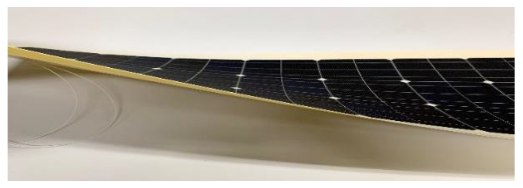
Bionic Stiffener Layout Optimization with a Flexible Plate in Solar-Powered UAV Surface Structure Design


Abstract
:1. Introduction
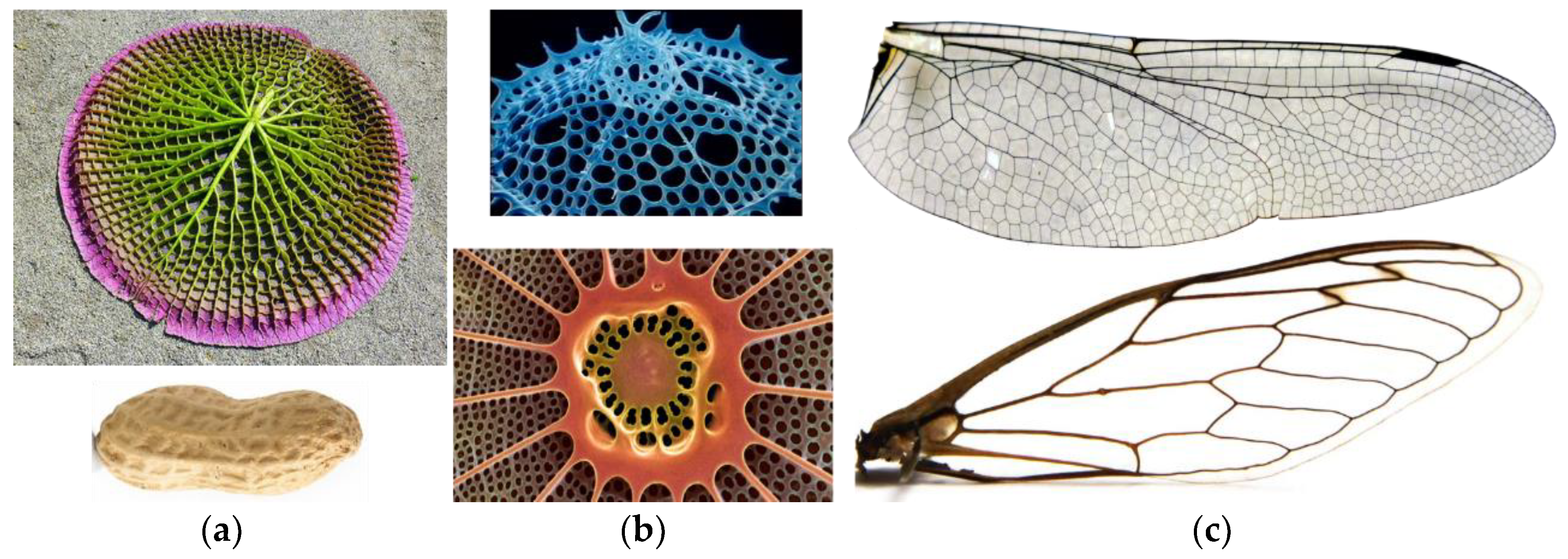
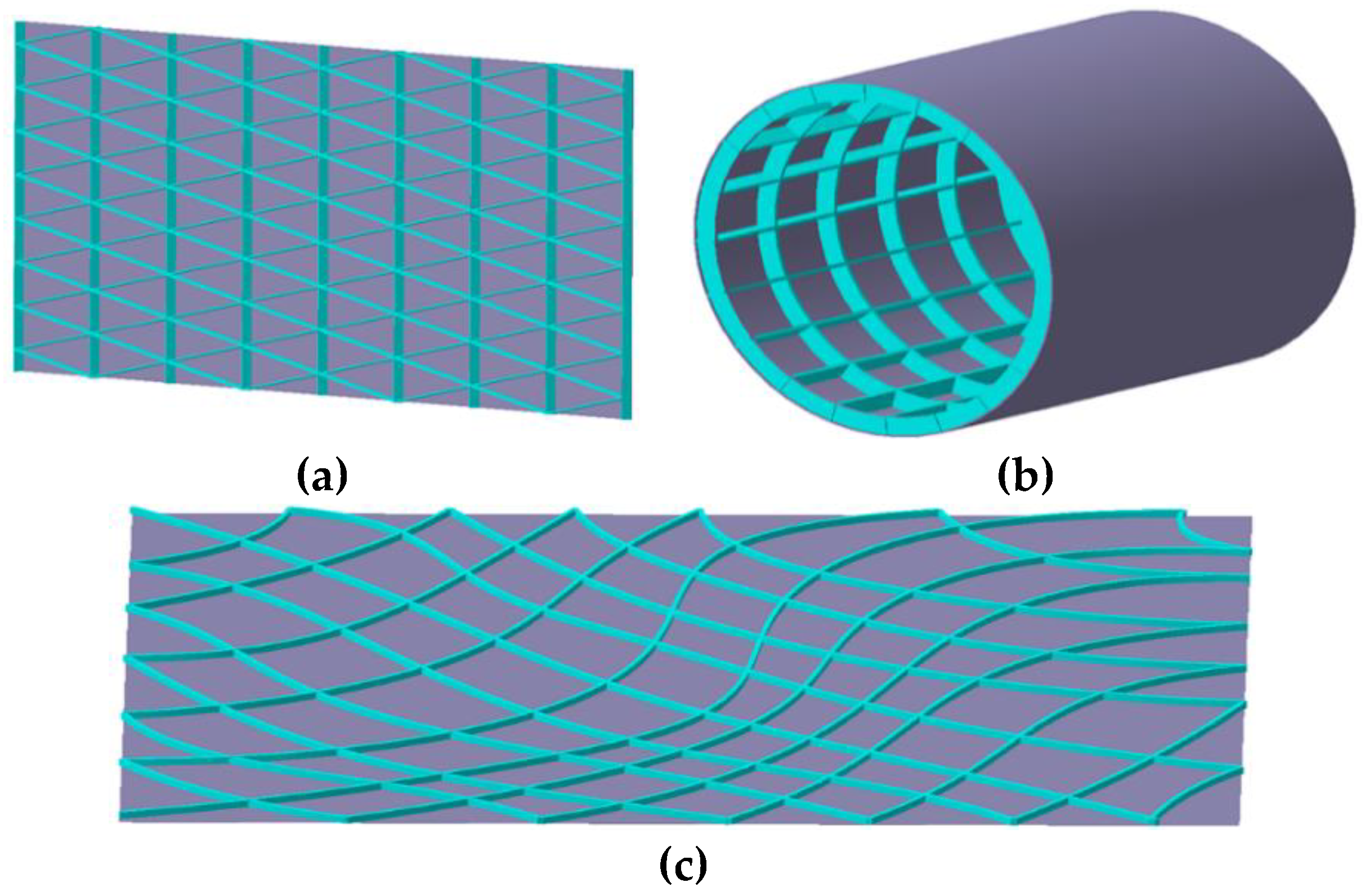
2. Bionic Concept of the Grid Generation Method
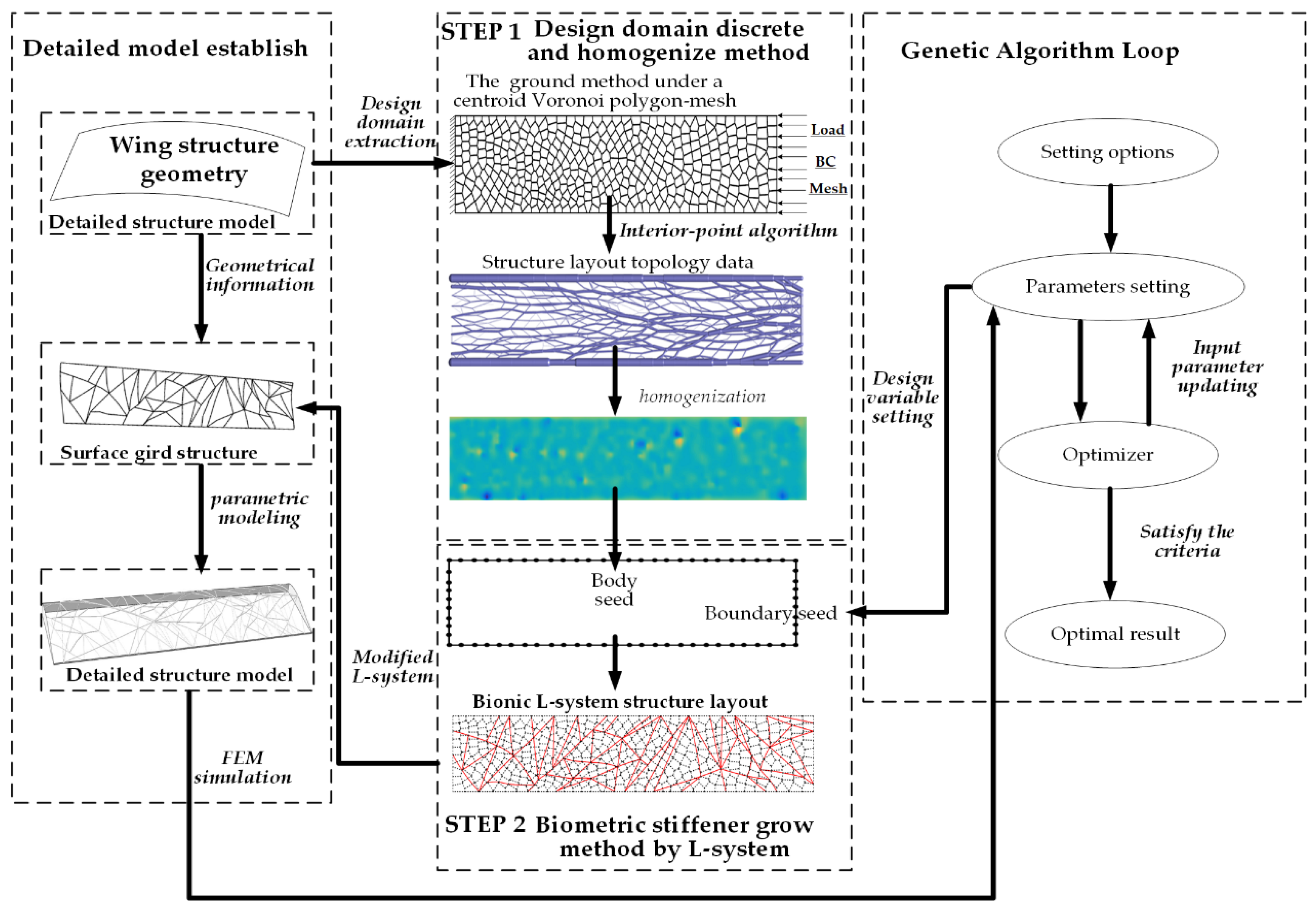
3. Modeling Framework
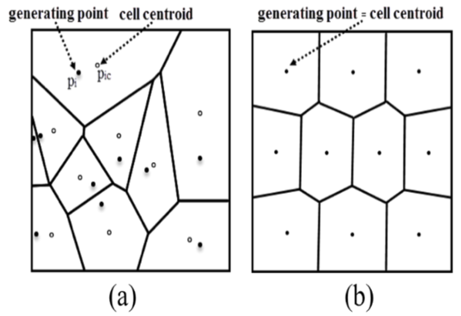
3.1. Ground Structure Method
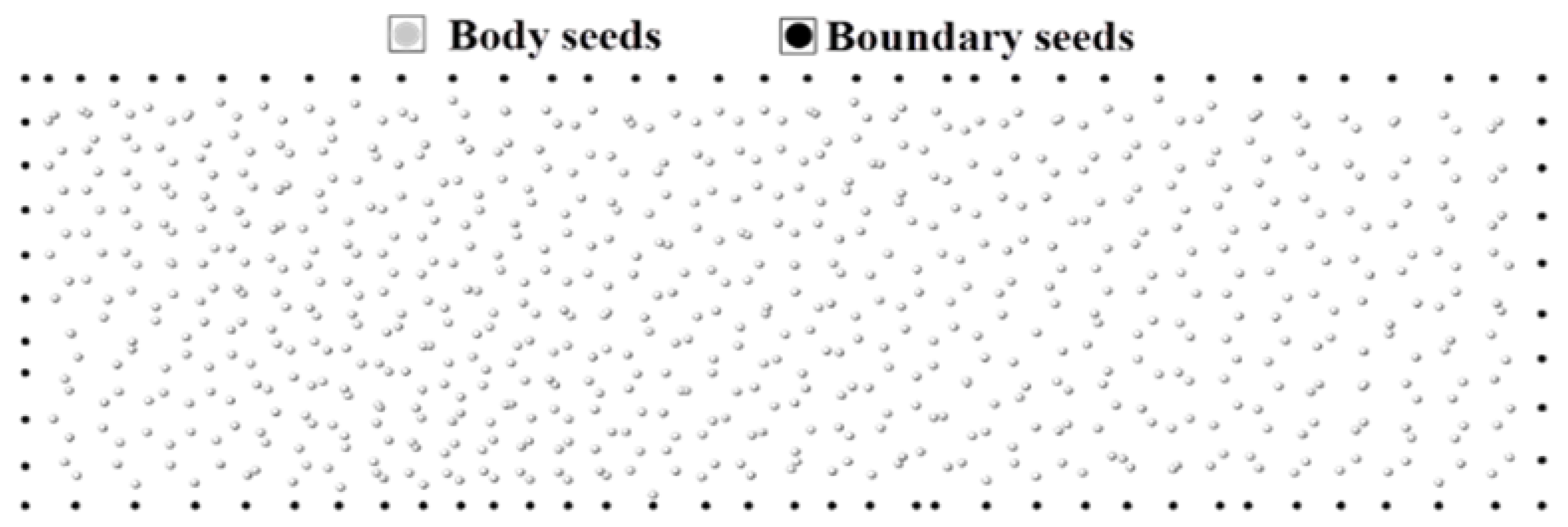
3.1.1. Discrete Strategy
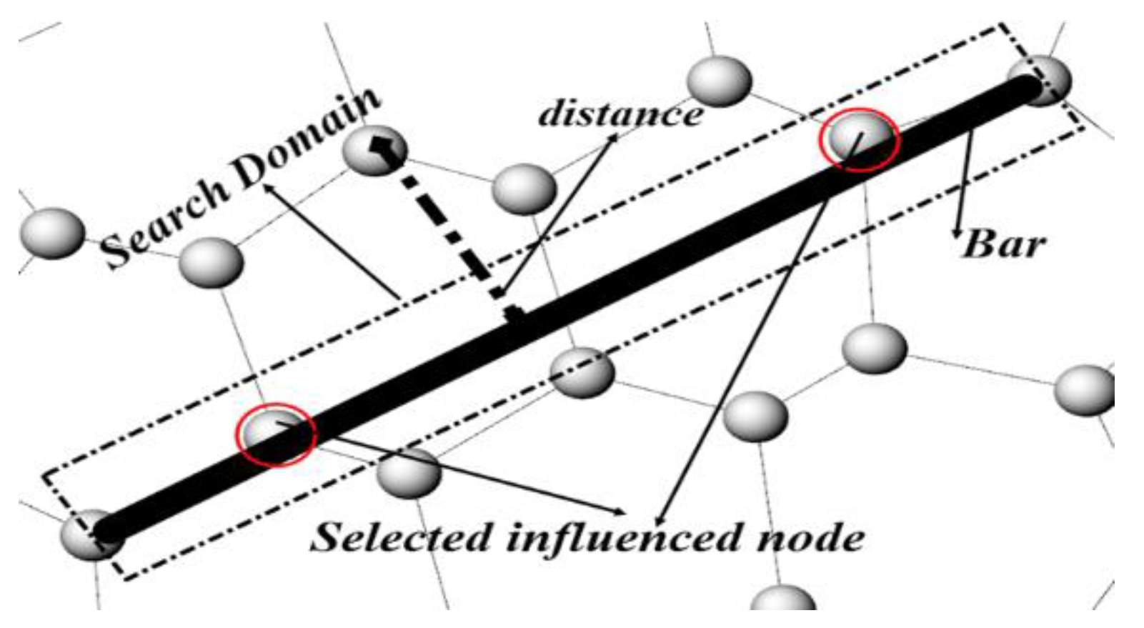
3.1.2. Homogenization Strategy
- (1)
- The searching domain is established among the two ends of the bar.
- (2)
- Calculating the distance from the corresponding point to the bar member.
- (3)
- Allocating the size parameter associated with the respective distance.
- (4)
- Data summation and normalization processing for every point, :
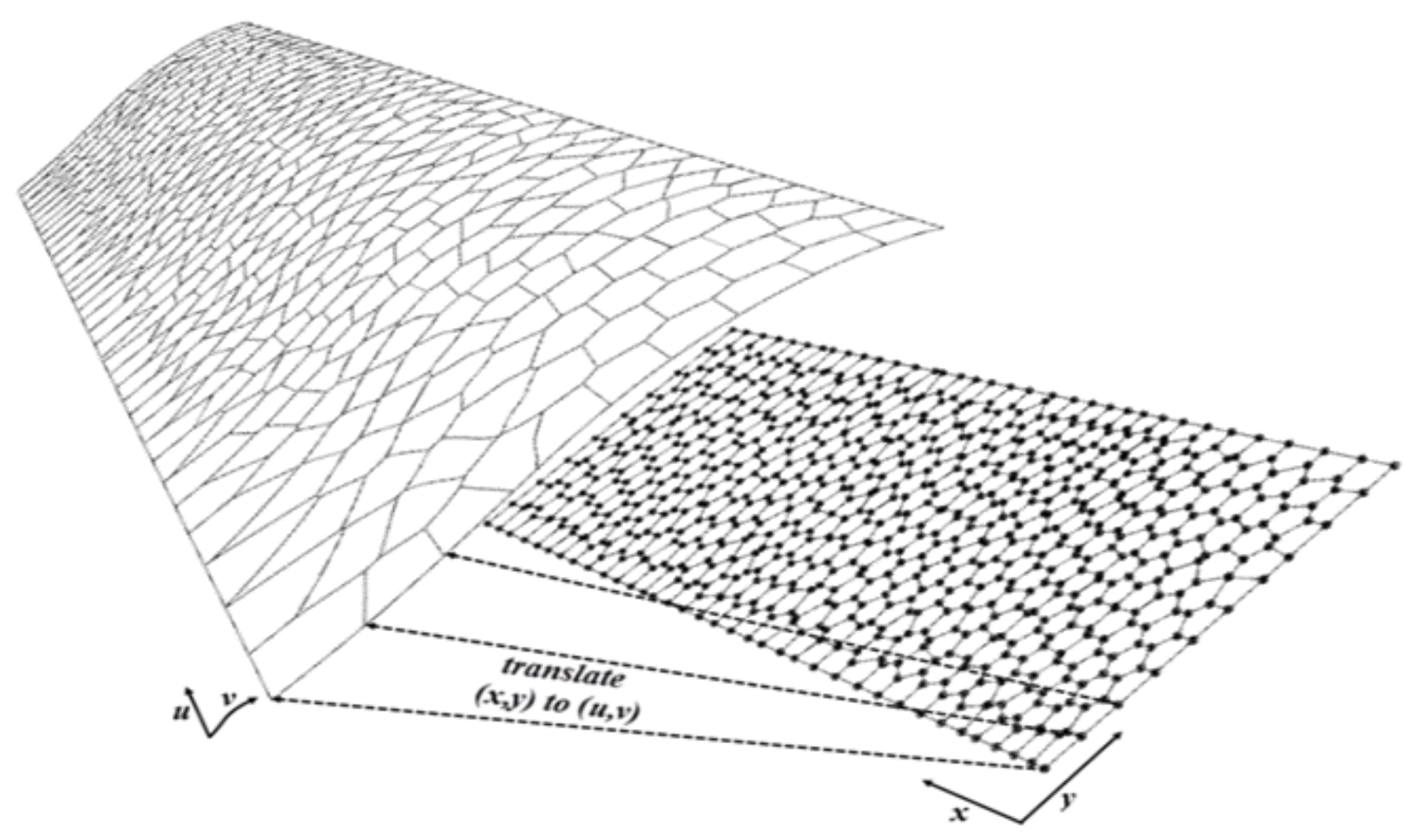
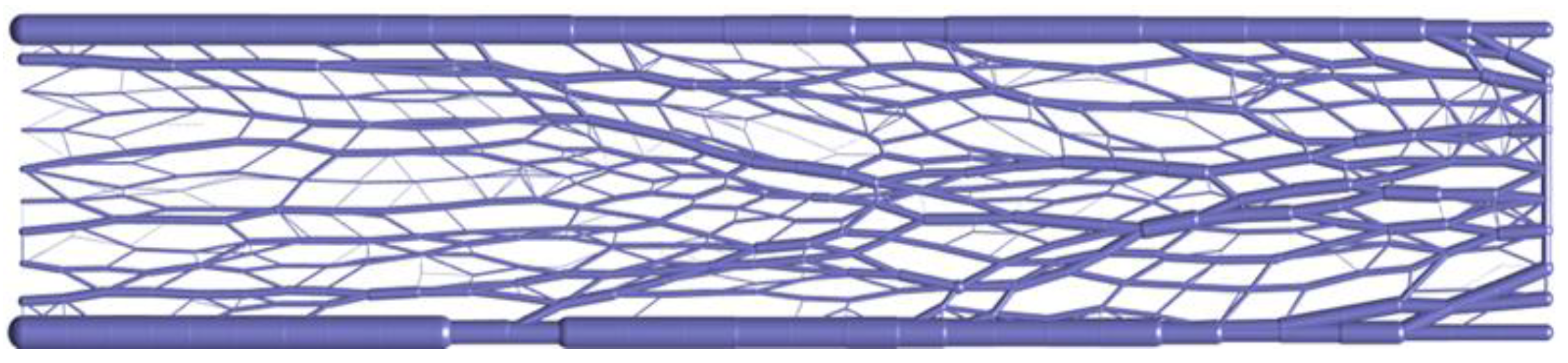
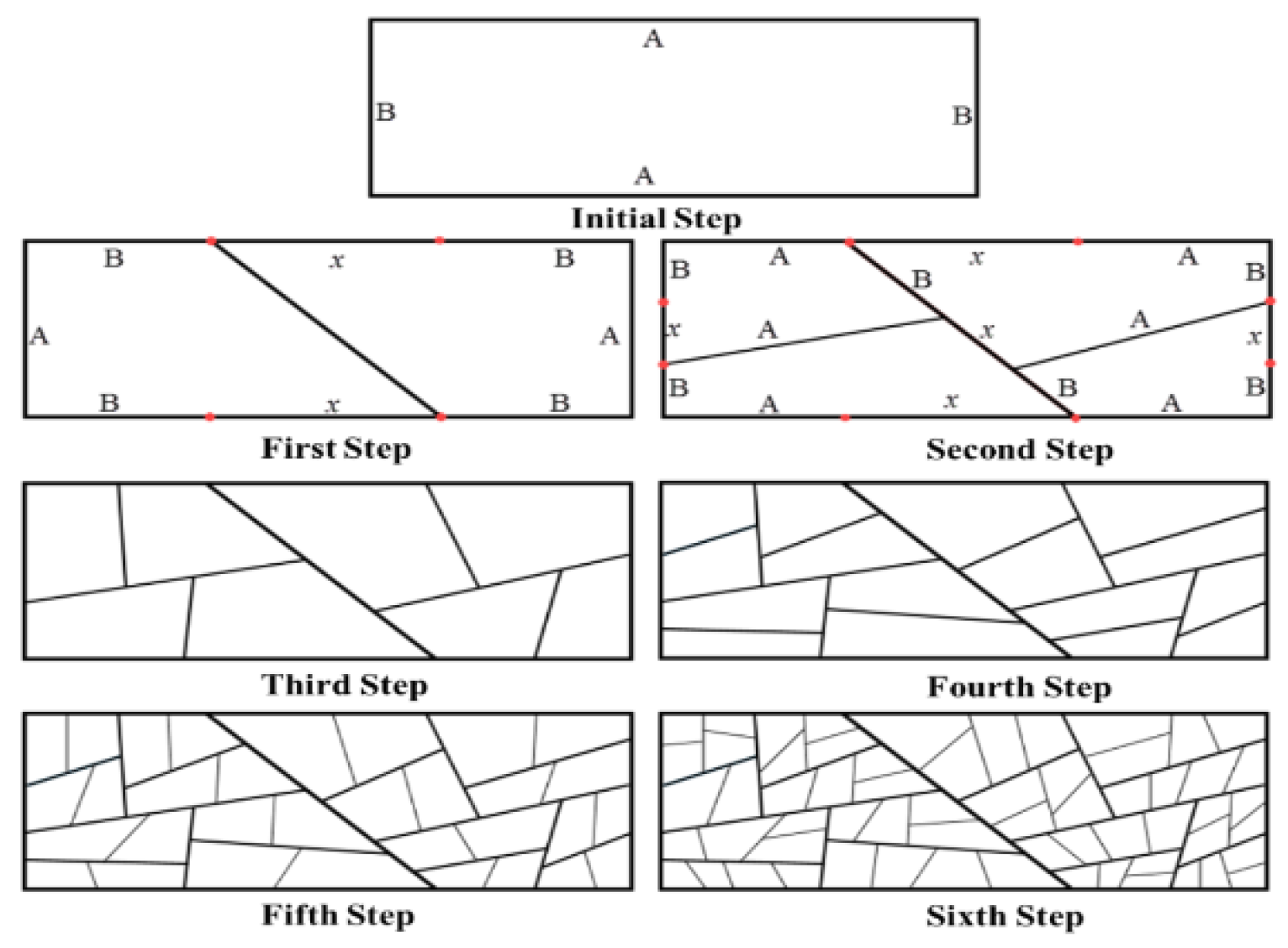
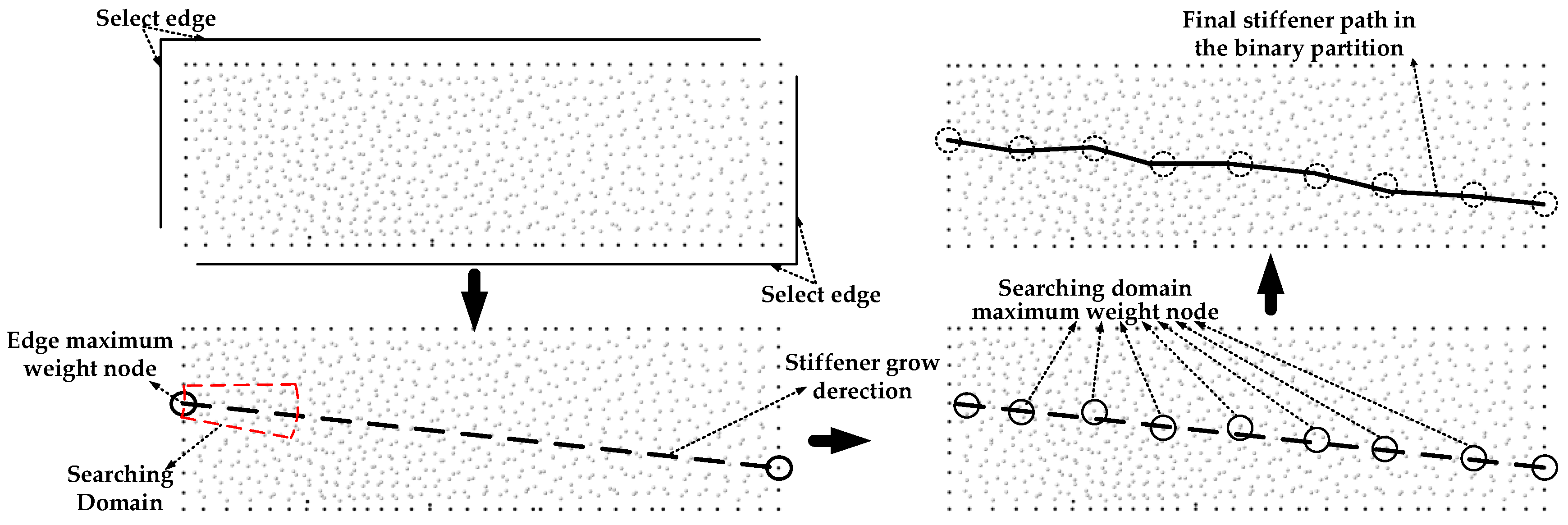
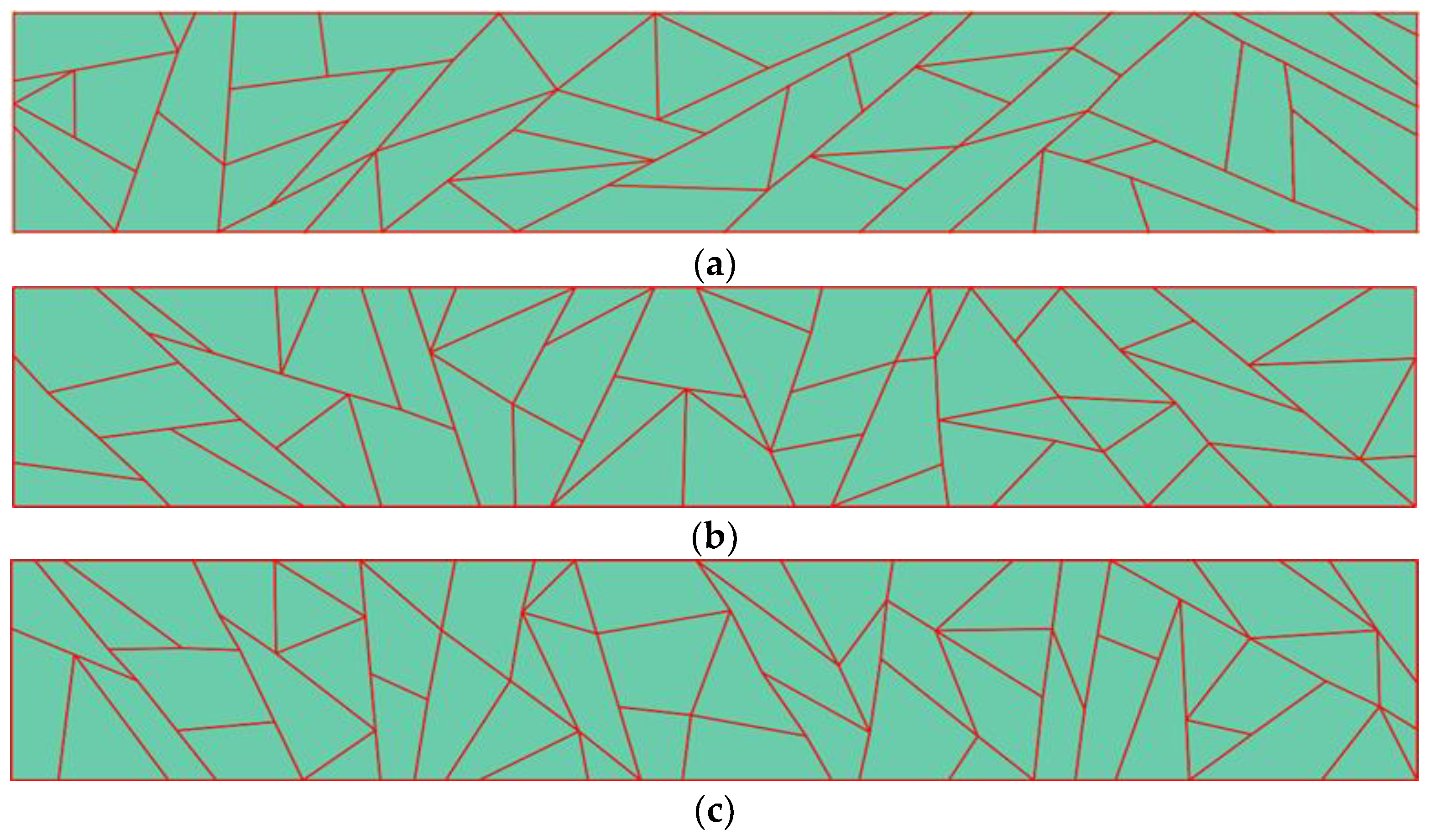
3.2. Map L Systems
Partition Strategy
4. Method Validation
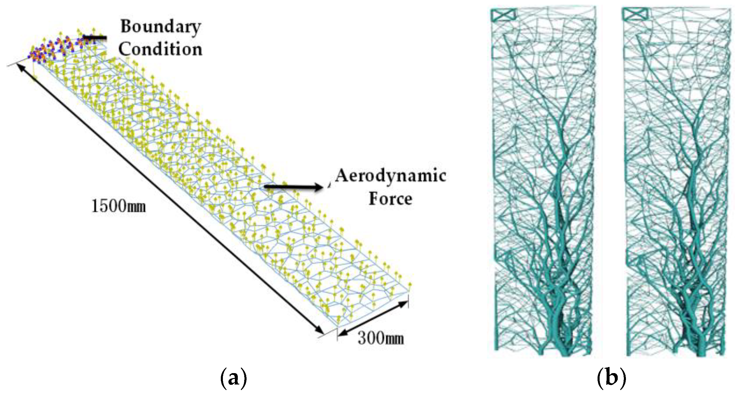
4.1. Model Extraction and Finite Element Analysis Preparation
4.2. Research Model Parameters
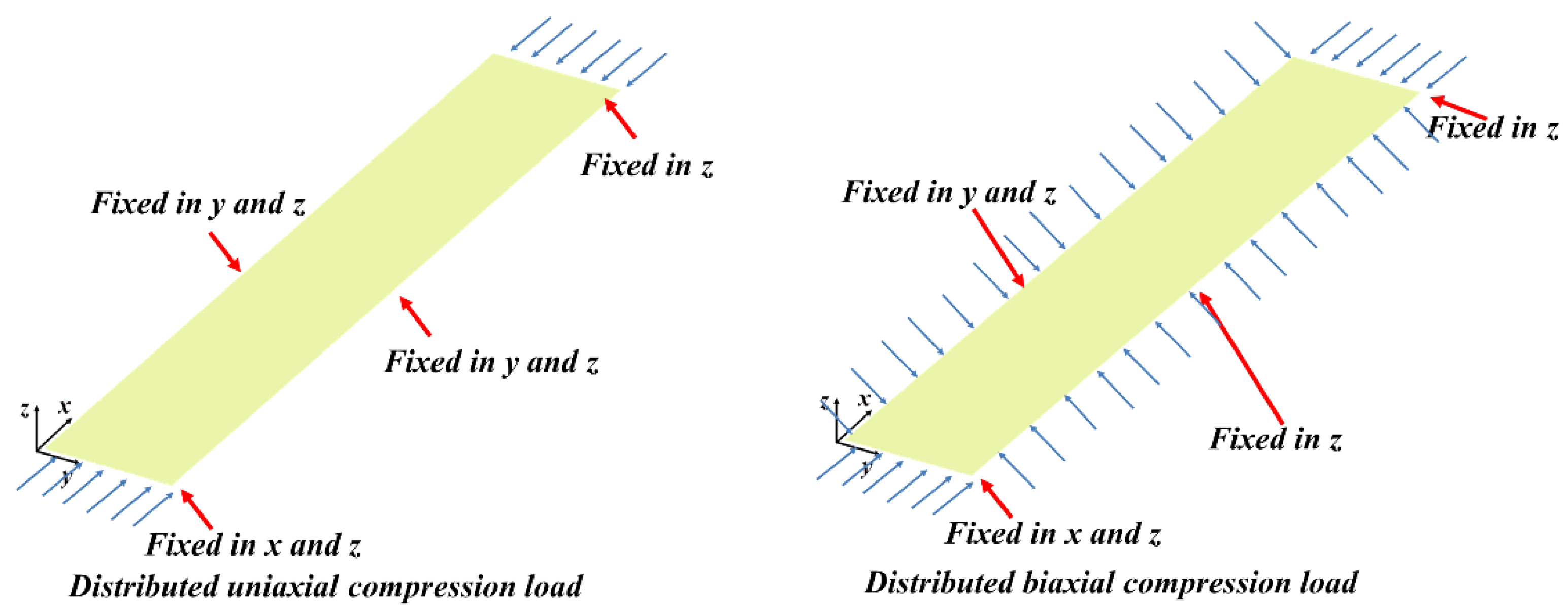
4.3. Optimization Model and Option Settings
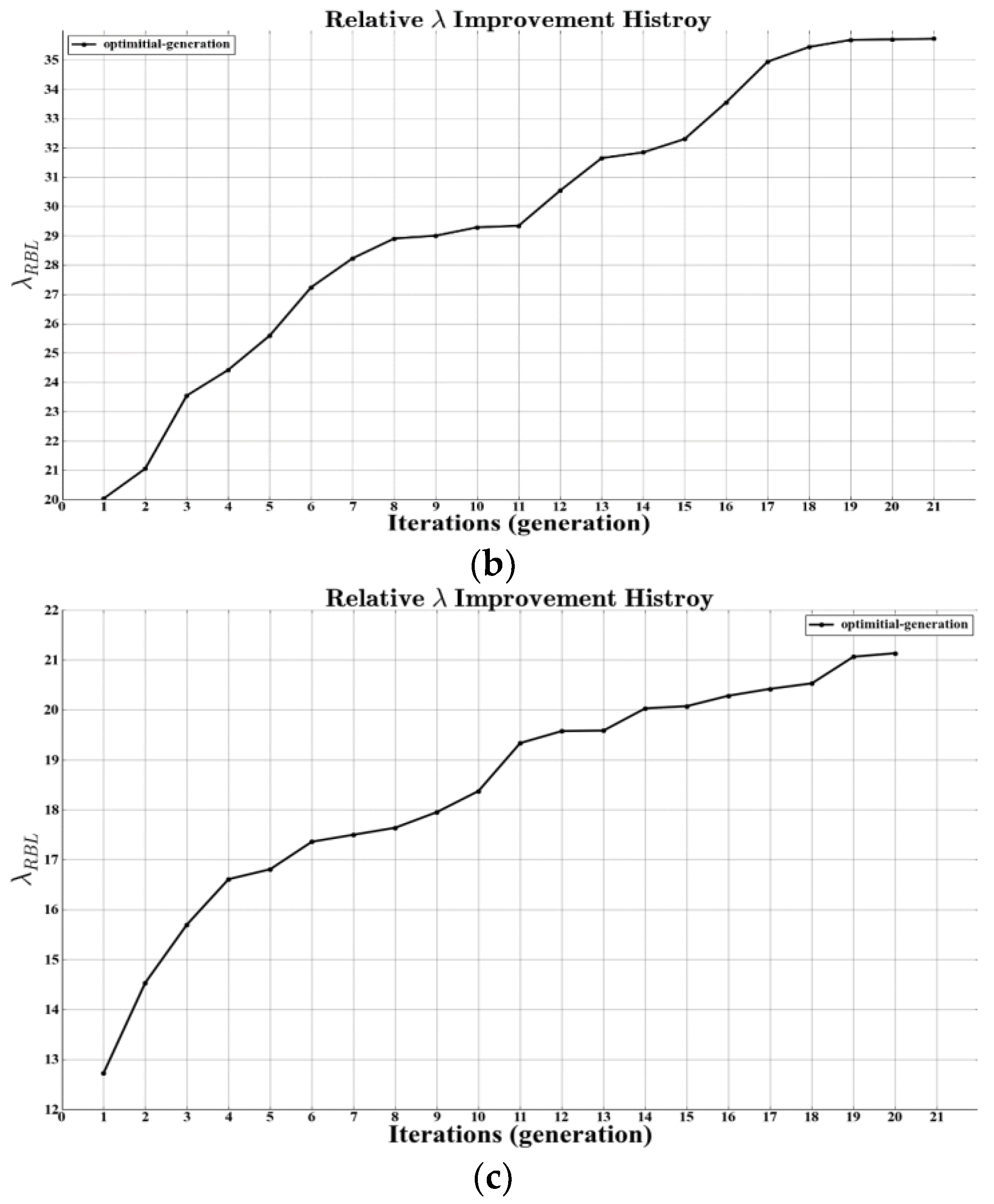
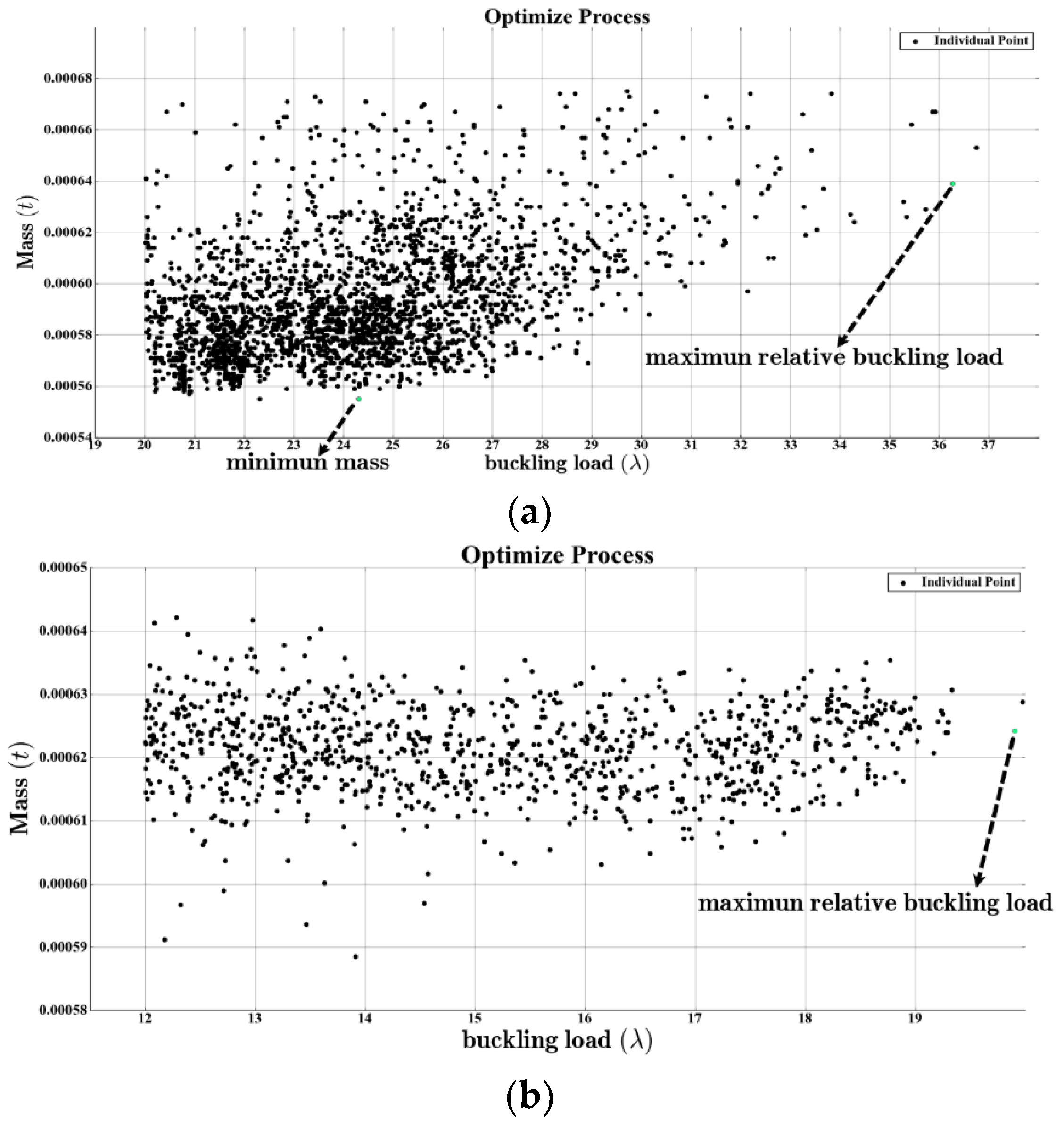
- The total weight of the whole model must be minimum, with the first buckling loads confined to a certain range.
- The first buckling loads, which are the objective of this design, should be maximum. These two optimization problems are presented as follows.
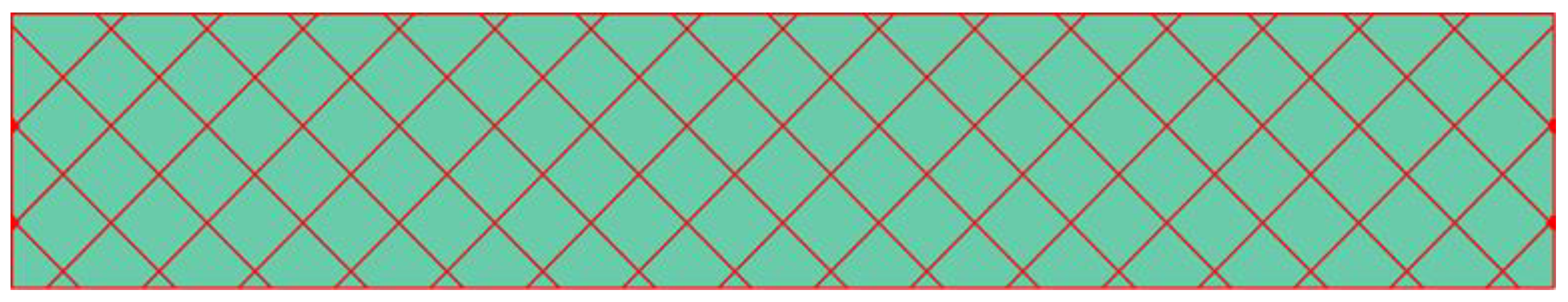
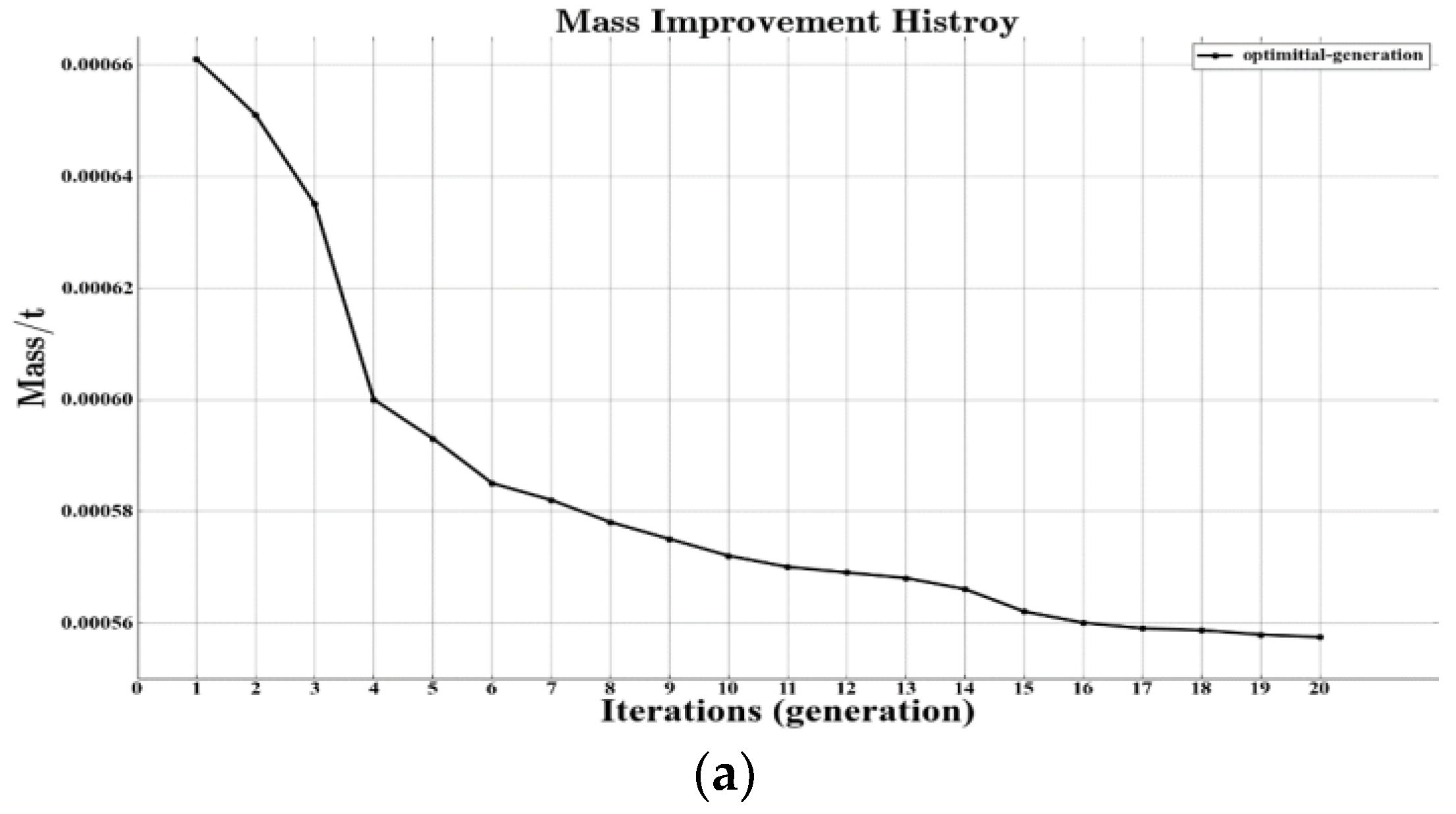
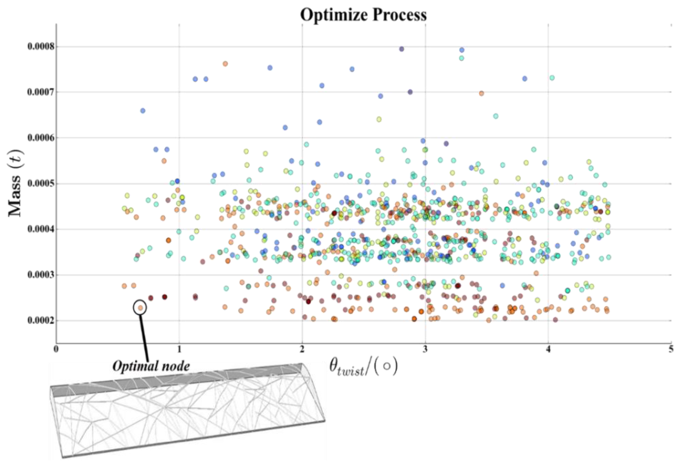
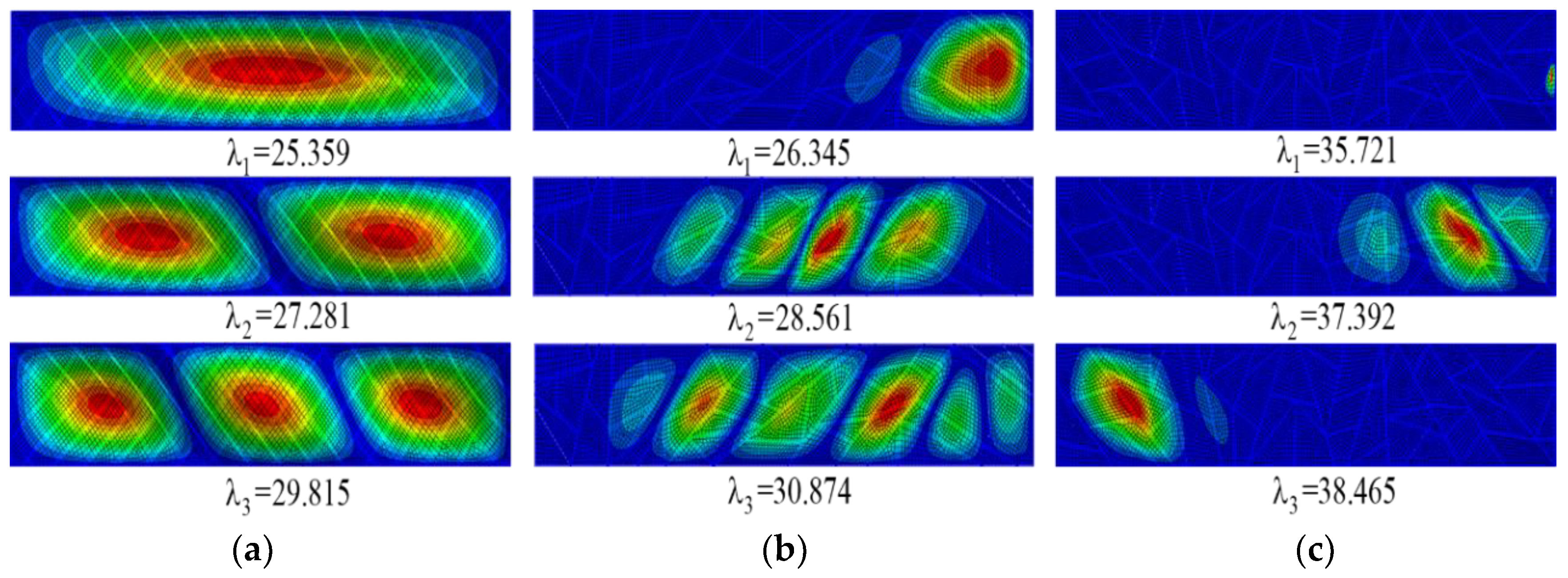
4.4. Result Analysis
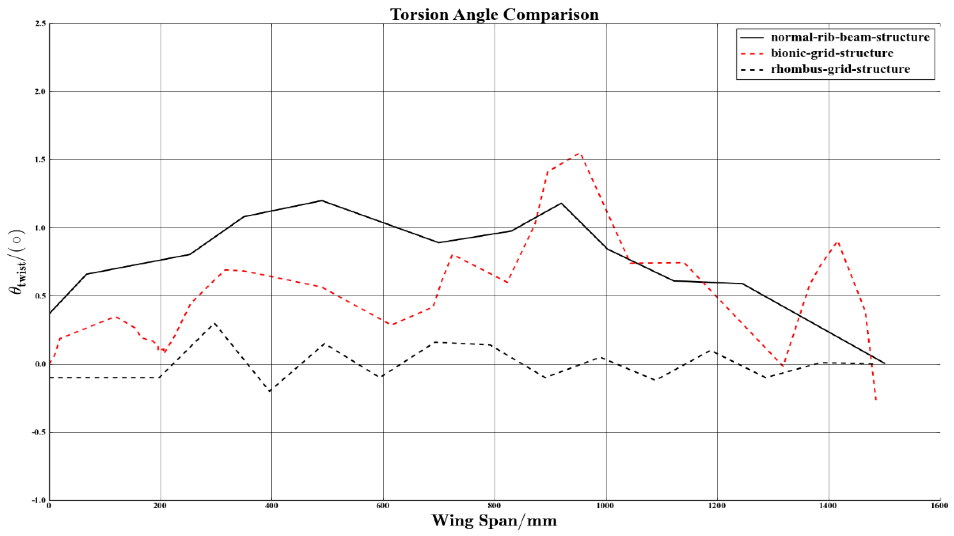
5. Wing Surface Structure Application
6. Conclusions
Author Contributions
Funding
Conflicts of Interest
References
- Shroff, S.; Acar, E.; Kassapoglou, C. Design, analysis, fabrication, and testing of composite grid-stiffened panels for aircraft structures. Thin-Walled Struct. 2017, 119, 235–246. [Google Scholar] [CrossRef]
- Hu, Y.; Li, W.; An, X. Fabrication and mechanical behaviors of corrugated lattice truss composite sandwich panels. Compos. Sci. Technol. 2016, 125, 114–122. [Google Scholar] [CrossRef]
- Huybrechts, S.M.; Hahn, S.E.; Meink, T.E. Grid stiffened structures: a survey of fabrication, analysis and design methods. In Proceedings of the 12th international conference on composite materials (ICCM/12), Paris, France, 5–9 July 1999. [Google Scholar]
- Gürdal, Z.; Olmedo, R. In-plane response of laminates with spatially varying fiber orientations: Variable stiffness concept. AIAA J. 1993, 31, 751–758. [Google Scholar] [CrossRef]
- Wang, D.; Abdalla, M.M.; Zhang, W. Sensitivity analysis for optimization design of non-uniform curved grid-stiffened composite (NCGC) structures. Compos. Struct. 2018, 193, 224–236. [Google Scholar] [CrossRef]
- Wang, D.; Abdalla, M.M.; Wang, Z.P. Streamline stiffener path optimization (SSPO) for embedded stiffener layout design of non-uniform curved grid-stiffened composite (NCGC) structures. Comput. Methods Appl. Mech. Eng. 2019, 344, 1021–1050. [Google Scholar] [CrossRef]
- Slemp, W.C.H.; Bird, R.K.; Kapania, R.K. Design, Optimization, and Evaluation of Integrally Stiffened Al-7050 Panel with Curved Stiffeners. J. Aircr. 2011, 48, 1163–1175. [Google Scholar] [CrossRef]
- Rouhi, M.; Ghayoor, H.; Hoa, S.V. Effect of structural parameters on design of variable-stiffness composite cylinders made by fiber steering. Compos. Struct. 2014, 118, 472–481. [Google Scholar] [CrossRef]
- Dimcic, M. Structural Optimization of Grid Shells Based on Genetic Algorithms. Ph.D. Thesis, University of Stuttgart, Stuttgart, Germany, 2011. [Google Scholar]
- Nagy, D.; Zhao, D.; Benjamin, D. Nature-Based Hybrid Computational Geometry System for Optimizing Component Structure; Springer: Singapore, 2018; pp. 167–176. [Google Scholar]
- Nagy, D. Nature-Based Hybrid Computational Geometry System for Optimizing the Interior Structure of Aerospace Components. In ACM SIGGRAPH 2017 Talks; ACM: New York, NY, USA, 2017; p. 76. [Google Scholar]
- Hamm, C.; Jansen, S.; Philipp, B. Verfahren Evolutionary Light Structure Engineering (ELiSE). Counterpoints 2008, 138, 33–43. [Google Scholar]
- Maier, M.; Siegel, D.; Hamm, C. Transfer of natural micro structures to bionic lightweight design proposals. J. Bionic Eng. 2013, 10, 469–478. [Google Scholar] [CrossRef]
- Zhu, J.H.; Li, Y.; Zhang, W.H. Shape preserving design with structural topology optimization. Struct. Multidiscip. Optim. 2016, 53, 893–906. [Google Scholar] [CrossRef]
- Bendsøe, M.P.; Sigmund, O. Topology Optimization: Theory, Methods and Applications; Springer: Berlin, Germany, 2003; pp. 221–259. [Google Scholar]
- Zegard, T.; Paulino, G.H. GRAND—Ground structure based topology optimization for arbitrary 2D domains using MATLAB. Struct. Multidiscip. Optim. 2014, 50, 861–882. [Google Scholar] [CrossRef]
- Zegard, T.; Paulino, G.H. GRAND3—Ground structure based topology optimization for arbitrary 3D domains using MATLAB. Struct. Multidiscip. Optim. 2015, 52, 1161–1184. [Google Scholar] [CrossRef]
- Du, Q.; Gunzburger, M. Grid generation and optimization based on centroidal Voronoi tessellations. Appl. Math. Comput. 2002, 133, 591–607. [Google Scholar] [CrossRef]
- Stanford, B.; Beran, P.; Kobayashi, M. Simultaneous topology optimization of membrane wings and their compliant flapping mechanisms. AIAA J. 2013, 51, 1431–1441. [Google Scholar] [CrossRef]
- Pedro, H.T.C.; Kobayashi, M.H. On a cellular division method for topology optimization. Int. J. Numer. Methods Eng. 2011, 88, 1175–1197. [Google Scholar] [CrossRef]
- Bielefeldt, B.R.; Akleman, E.; Reich, G.W.; Beran, P.S.; Hartl, D.J. Expanding the Design Space Via Graph-Based Interpretation of L-System Encodings for Topology Optimization of Multifunctional Structures Expanding the Design Space Via Graph-Based. In Proceedings of the 29th International Conference on Adaptive Structures and Technologies, Seoul, Korea, 30 September–4 October 2018. [Google Scholar]
- Bielefeldt, B.R.; Hartl, D.J.; Akleman, E. L-System-Generated Topology Optimization of Compliant Mechanisms Using Graph-Based Interpretation. In Proceedings of the ASME 2018 International Design Engineering Technical Conferences and Computers and Information in Engineering Conference, Quebec City, QC, Canada, 26–29 August 2018. [Google Scholar]
- Lund, E. Buckling topology optimization of laminated multi-material composite shell structures. Compos. Struct. 2009, 91, 158–167. [Google Scholar] [CrossRef]
- Mallikarachchi, H.; Pellegrino, S. Quasi-static folding and deployment of ultrathin composite tape-spring hinges. J. Spacecr. Rocket. 2011, 48, 187–198. [Google Scholar] [CrossRef]


| Material Properties | Value |
|---|---|
| Longitudinal stiffness, E1 [N/mm2] | 157,650 |
| Transverse stiffness, E2 = E3 [N/mm2] | 13,280 |
| Shear stiffness, G12 = G13 [N/mm2] | 4561 |
| In-plane shear stiffness, G23 [N/mm2] | 4538 |
| Poisson’s ratio, ν12 = ν13 | 0.256 |
| Optimization Technique Options | Value |
|---|---|
| Number of designs per generation | 50 |
| Number of generations | 30 |
| Number of islands | 5 |
| Mutation rate | 0.01 |
| Cross-over rate | 1.0 |
| Mutation rate | 0.03 |
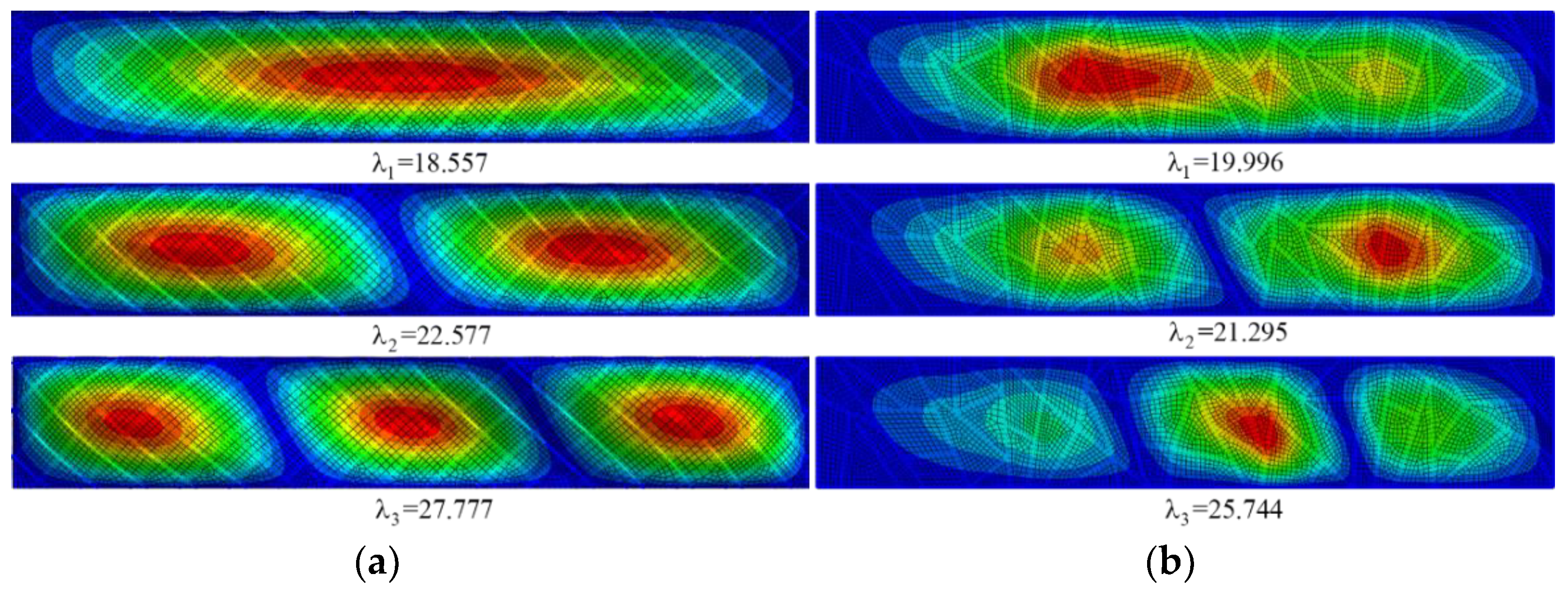
| Mode | Uniaxial Compressions | Biaxial Compressions | |||
|---|---|---|---|---|---|
| Detailed Models | Detailed Models | ||||
| Initial Straight | Optimal Mass | Optimal RBL | Initial Straight | Optimal RBL | |
| 1 | 25.359 | 26.345 | 35.721 | 18.557 | 19.996 |
| 2 | 27.281 | 28.561 | 37.392 | 22.577 | 21.295 |
| 3 | 29.815 | 30.874 | 38.465 | 27.777 | 25.744 |
| Mass/kg | 0.663 | 0.557 | 0.630 | 0.663 | 0.624 |
| RBL | 25.359 | —— | 35.542 | 18.557 | 21.172 |
| Increase (RBL) | —— | —— | 40.15% | —— | 14.09% |
| Increase (Mass) | —— | 15.98% | —— | —— | —— |
| Optimization Technique Options | Value |
|---|---|
| Number of designs per generation | 40 |
| Number of generations | 25 |
| Number of islands | 5 |
| Mutation rate | 0.01 |
| Cross-over rate | 1.0 |
| Mutation rate | 0.03 |
| Maximum stress limit | 900 MPa |
| Maximum displacement limit | 150 mm |
| Twist angle limit | |
| Mass | —— |
| Design Object and Constraint | Optimal Result | ||
|---|---|---|---|
| Bionic Grid | Tradition Structure | Initial Straight | |
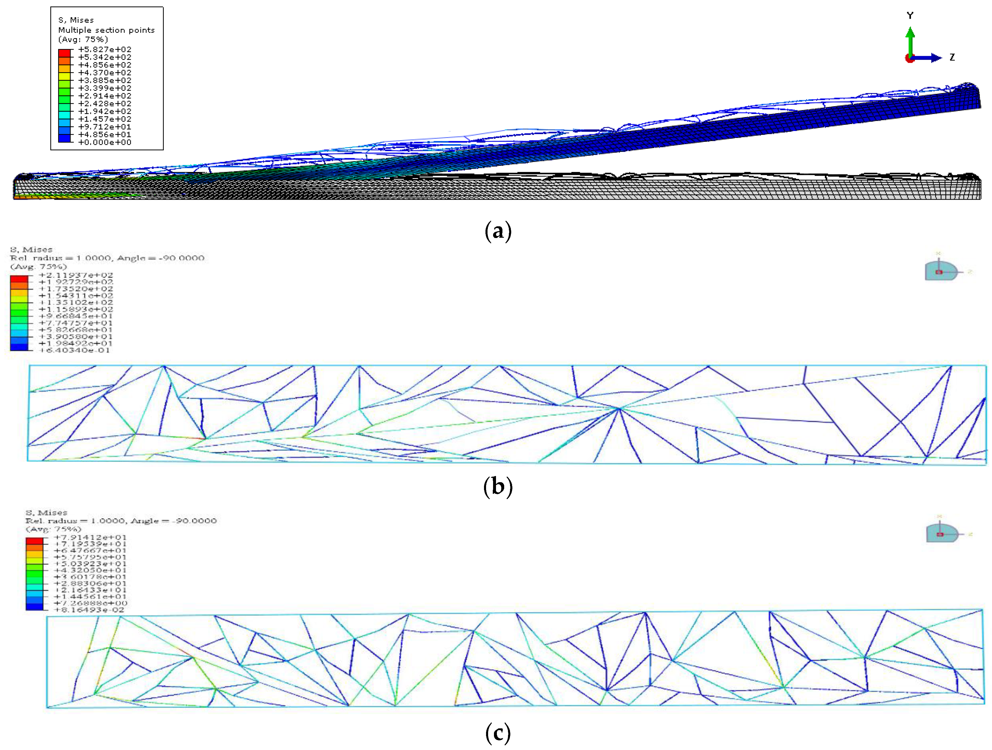
| Graphical representation |  |  | 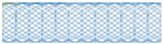 |
| Maximum stress | 582.7 MPa | 27.1 MPa | 453.3 MPa |
| Maximum displacement | 126 mm | 36.2 mm | 43.6 mm |
| Twist angle limit | 1.52° | 1.23° | 0.6° |
| Mass | 250 g | 353 g | 324 g |
© 2019 by the authors. Licensee MDPI, Basel, Switzerland. This article is an open access article distributed under the terms and conditions of the Creative Commons Attribution (CC BY) license (http://creativecommons.org/licenses/by/4.0/).
Share and Cite
Ding, Y.; Zhou, Z.; Wang, Z.; Liu, H.; Wang, K. Bionic Stiffener Layout Optimization with a Flexible Plate in Solar-Powered UAV Surface Structure Design. Appl. Sci. 2019, 9, 5196. https://doi.org/10.3390/app9235196
Ding Y, Zhou Z, Wang Z, Liu H, Wang K. Bionic Stiffener Layout Optimization with a Flexible Plate in Solar-Powered UAV Surface Structure Design. Applied Sciences. 2019; 9(23):5196. https://doi.org/10.3390/app9235196
Chicago/Turabian StyleDing, You, Zhou Zhou, ZhengPing Wang, HongJun Liu, and KeLei Wang. 2019. "Bionic Stiffener Layout Optimization with a Flexible Plate in Solar-Powered UAV Surface Structure Design" Applied Sciences 9, no. 23: 5196. https://doi.org/10.3390/app9235196
APA StyleDing, Y., Zhou, Z., Wang, Z., Liu, H., & Wang, K. (2019). Bionic Stiffener Layout Optimization with a Flexible Plate in Solar-Powered UAV Surface Structure Design. Applied Sciences, 9(23), 5196. https://doi.org/10.3390/app9235196