Article

Design of a Novel Electric Diagnostic Technique for Fault Analysis of Centrifugal Pumps

1
Electrical Engineering Department, College of Engineering, Najran University Saudi Arabia, Najran 61441, Saudi Arabia
2
Department of Automatic, Control and Robotics, AGH University of Science and Technology, 30-059 Kraków, Poland
*
Author to whom correspondence should be addressed.
Appl. Sci. 2019, 9(23), 5093; https://doi.org/10.3390/app9235093
Submission received: 6 November 2019 / Revised: 18 November 2019 / Accepted: 19 November 2019 / Published: 25 November 2019
(This article belongs to the Section Mechanical Engineering)

Abstract

:
Centrifugal pumps are the fundamental components of most industries. They are used in almost every industry to transfer liquid through pipes. The breakdown of a pump causes heavy production losses, and hence, the development of an economical and user-friendly condition monitoring system is vital in order to estimate the health of a pump in a timely manner, and to avoid an unscheduled breakdown. The intrusive condition monitoring techniques (such as vibration analysis and acoustic emission) developed for the fault diagnosis of pumps utilize expensive vibration sensors, and these sensors need to be installed on the pump body for data collection. Non-intrusive techniques (such as motor current analysis) have been proven to be economical, but have limited capabilities for diagnosing the incipient faults in pumps operating in a noisy industrial environment. The electric diagnostic technique (EDT) proposed in this paper does not require the purchase of extra sensors, and instead utilizes the existing sensors, which are usually installed on the machines, to measure and display the motor line current and voltage. The EDT has been developed in the Laboratory Virtual Instrument Engineering Workbench (LabVIEW) so as to measure the three-phase line current, and then transform it into two-phase d–q currents. These d–q currents are plotted as patterns, and the statistical features of these patterns are used to segregate the centrifugal pump fault types. Detailed experiments and evaluations have been performed in order to check the viability of the developed EDT technique.

1. Introduction

Breakdown maintenance was common practice in the earlier history of plant maintenance. Maintenance personnel would start the action when the plant was shut down as a result of a problem in any of the components of a machine [1,2,3]. As this type of maintenance was performed in reaction to a problem, it was named reactive maintenance. It was costly and time-consuming. Later on, the concept of scheduled maintenance was introduced, in which the parts of the machine were changed after a specific run-time, as recommended by the manufacturers. This maintenance strategy was also not optimal, as some parts were replaced while they were still in good working condition. To rectify these issues, plant engineers introduced the predictive maintenance concept, where the machine parts, performance, and health were monitored continuously, and maintenance was preplanned before the breakdowns [4,5,6].
A centrifugal pump is a rotating machine used in the industry for the transfer of liquids through pipes. An unscheduled shutdown of a centrifugal pump in continuous process plants causes a huge financial loss in terms of maintenance, cost, and downtime [7]. The maintenance cost distribution for the rotating machines at a petrochemical plant is shown in Figure 1 [8,9]. It has been observed that 70% of the maintenance cost is associated with the pump. Therefore, a significant improvement in maintenance technology is required in order to reduce the maintenance cost associated with pumps.
The centrifugal pump, as shown in Figure 2, mainly consists of two parts, which are the induction motor and the pump assembly. The pump assembly has a further two main parts, which are the impeller and the bearings [10,11].
Impeller faults and pipe blockages are the main reason for the breakdown of a centrifugal pump. In the past, centrifugal pump faults have been investigated through vibration analysis and acoustic emission techniques. The sensors used in the vibration analysis and acoustic emission analysis techniques are expensive. Furthermore, the vibration sensors and acoustic emission sensors need to be installed on the machine for data collection. Some machines in the industry are located in complex positions, and it could be impossible to access the machine for sensor installation. Comparatively, this paper has proposed and developed an electric diagnostic technique that uses stator current sensors that are installed on the electric supply of the machine. Thus, the proposed technique is non-intrusive, as it does not require access to the machine for sensor installation. Furthermore, the stator current sensors are cheaper than the vibration sensors. The stator current sensors are usually installed in the plants in order to display the line current, and information from the same sensors could be utilized for fault diagnostic purposes. Thus, the proposed system in this paper is economical when compared with the vibration analysis and acoustic emission techniques [12,13].
Rotating-machine health can be examined through an analysis of the supply voltage, line current, and instantaneous power. Faults in the machine (i.e., impeller faults or pipe blockages) produce harmonics in the stator current and instantaneous power. An analysis of these harmonic frequencies could give an indication of machine health [14,15,16]. It is a non-invasive method, as the measurement of the stator current is performed through the power distribution boxes, without requiring access to the machine position [17]. Thus, this method is useful to examine the health of machines operating in hazardous and extreme environments, and where accessibility to the machine is difficult, for example, in nuclear power plants, chemical plants, paper mills, and on-shore and off-shore facilities [18]. The main limitation of this method is that amplitude detection in the motor current signature analysis (MCSA) is affected by the amplitude of random environmental noise. Furthermore, MCSA requires a harmonic frequency model to identify fault-related harmonics. These harmonic frequency models are available only for bearing defects, and models for impeller faults and pipe blockages do not exist. Thus, the MCSA technique cannot diagnose such faults [19,20,21]. The instant power technique has been suggested as an alternative non-invasive approach to MCSA for diagnosing bearing faults in an induction motor [22]. The mathematical model of the instant power technique provides an extra harmonic frequency related to the faults, and provides more information related to the health of the machine. However, the instant power technique requires information from the current sensor and the voltage sensor, and has thus been proven to be expensive when compared with MCSA [23,24]. Furthermore, the capability of the instant power technique to diagnose pump impeller and cavity faults has yet to be investigated.
Park’s vector analysis of the motor current has been used by some researchers to analyze the bearing, eccentricity, and rotor faults [25,26,27,28]. In their work, the three-phase current has been converted to a two-phase current, and the frequency analysis of the two-phase current spectrum gives information about the machine health. Although the frequency spectrum of the two-phase current gives better information about the machine faults, the intensive mathematical computation is a major limitation [28]. Furthermore, the capability of the two-phase analysis technique to diagnose centrifugal pump faults has never been investigated in previously published research.
The main contribution of this paper is to develop a non-intrusive EDT to diagnose impeller faults and pipe blockages. The developed EDT collects the three-phase currents from the sensors, and transforms them into two-phase d–q currents. These d–q currents are plotted to get d–q patterns. The visual and statistical analyses of these d–q patterns give the health status of the centrifugal pump.
The rest of the paper is structured as follows: Section 2 gives the components of the fault analysis test rig. Section 3 provides an analysis of the results. Finally, Section 4 provides conclusions.

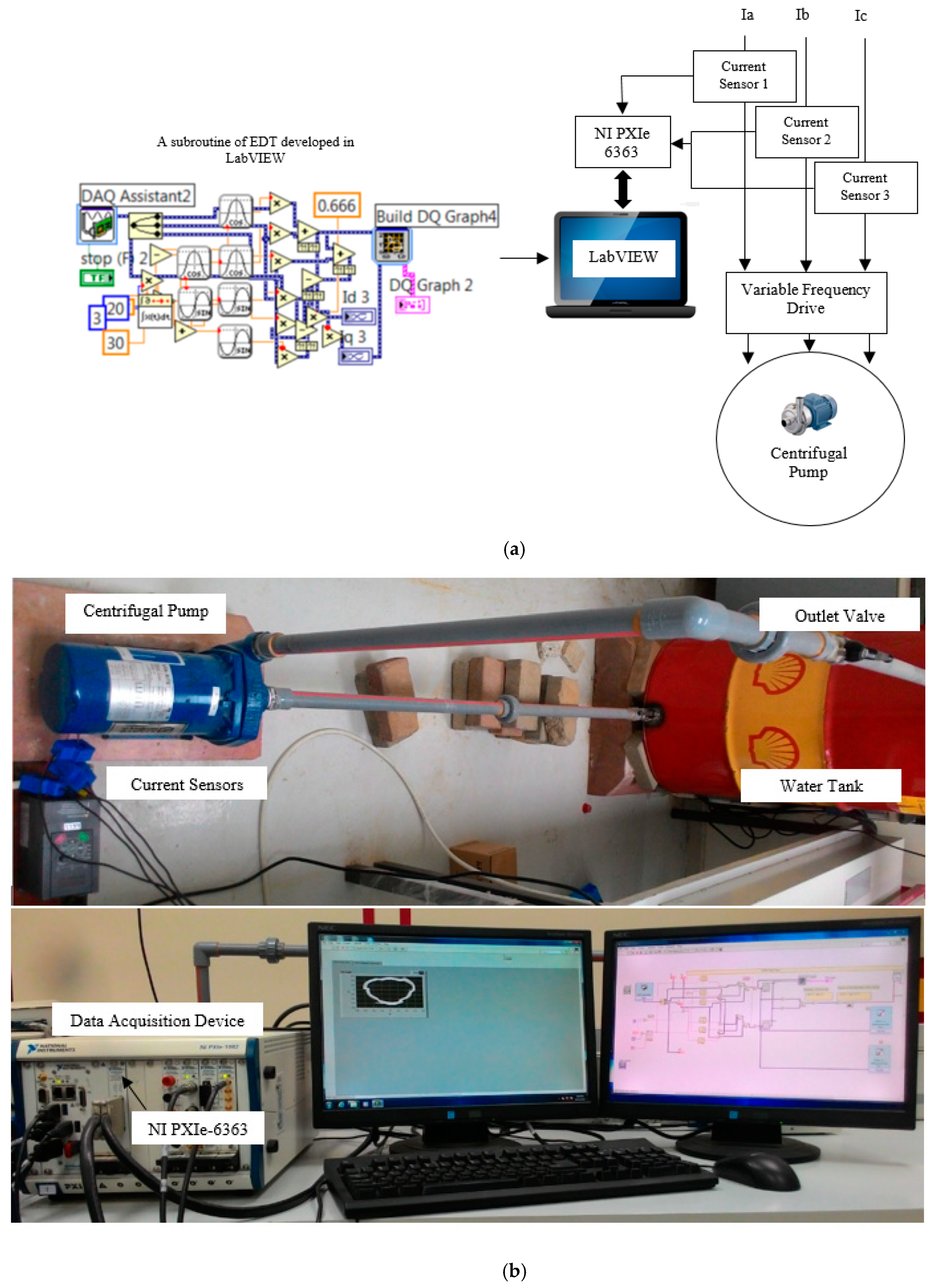
2. Fault Analysis Test Setup

An EDT-based fault diagnosis system has been developed using components such as a centrifugal pump, data acquisition module (PXIe-1082(National Instruments, Budapest; Hungary)), Laboratory Virtual Instrument Engineering Workbench (LabVIEW), variable frequency drive (KOC100-2R2T4(Shenzhen KCLY Electric Co., Ltd, Shenzhen; China)), and current sensors (SCT-013-10(YHDC, Qinhuangdao; China), input: 0~10 A, output: 0~1 V). The current sensors are interfaced with a PXIe-6363 card, which has been installed in the chassis of the PXIe-1082. The continuous data acquisition mode of the data acquisition assistant in LabVIEW was used to collect the data. Then, 1000 samples of the three-phase stator current were collected from the current sensors at a 4 kHz sampling rate, and were analyzed in LabVIEW. The EDT was developed so as to convert the three-phase quantities into two-phase d–q quantities. These two-phase d–q quantities were transformed into d–q patterns. These d–q patterns provide a visual analysis and an indication of the pump health condition. Furthermore, an algorithm was developed in LabVIEW to calculate the statistical features (such as the shape and thickness) of these d–q patterns, and the segregation of various d–q patterns was performed based on these statistical features. The block diagram of the proposed condition monitoring system and the developed test set-up is shown in Figure 3. The centrifugal pump (JHF3X-51SAE (SAMNAN Saudi Arabia, Riyadh; Saudi Arabia), three-phase, 1.5 HP, 3450 rpm) was operated at a full speed of 3000 rpm, at 50 Hz. The flow chart of the proposed EDT-based condition monitoring system is shown in Figure 4.
The faults in the impeller were created in the laboratory by artificial damage. Impeller fault type 1 was created by damaging the impeller surface, as shown in Figure 5. Similarly, impeller fault types 2 and 3 were created at an angle of 120°. The pipe blockages were created by closing the hand valve, as shown in Figure 6.

3. Results and Analysis

The d–q patterns of the two-phase currents were plotted using the EDT programmed in LabVIEW. The plot of the healthy pump is shown in Figure 6, and the d–q plots of the impeller faults and pipe blockages are shown in Figure 7; Figure 8, respectively.
The d-q patterns, shown in Figure 6, Figure 7 and Figure 8, for the various health conditions of the centrifugal pump, could be analyzed on site by machine operators through a visual comparison of the various patterns. This visual comparison can give information to machine operators about the health condition of the pump, and they can then plan the maintenance for any upcoming failure. On the other hand, a statistical analysis of the various patterns was also performed for automatic decision making regarding the centrifugal pump health. The statistical analysis technique, based on the calculation of the splitting factor of the curve, was used in this paper for the analysis of the d-q patterns of the pump [14]. The mathematical model of the splitting factor is included in the Appendix A. The algorithm for calculating the statistical parameter (splitting factor) was incorporated in the LabVIEW-based EDT, and the results are shown in Table 1.
It has been observed from Table 1 that each type of centrifugal pump fault has its unique splitting factor, and the splitting factor increases with the increase in fault severity. Thus, the centrifugal pump health could be estimated, and various fault types could be segregated based on the curve splitting factor. The uniqueness of the splitting factor of the impeller faults and pipe blockages has been confirmed by comparing the results with other fault types, and this is shown in Table 2. The authors of [14] calculated the splitting factor for the outer race and inner race faults, which were reported to be 1.75 and 1.70, respectively. The splitting factor for a motor winding inter-turn short circuit was shown to be 1.8 [29]. Similarly, the splitting factor for a motor eccentricity fault was shown to be 1.64 [30]. The current study calculated the splitting factor for three fault levels of impeller faults and two levels of pipe blockages. The splitting factor values were unique for each fault type. Thus, the splitting factor information could be used in online fault diagnostic applications for the identification and segregation of various fault types.
The superiority of EDT has been compared with other published techniques in order to verify the importance and usability of EDT in centrifugal pump fault diagnostics. The vibration analysis technique was used by the authors of [7,11] to diagnose seal damage and cavity faults in pumps. Although vibration analysis has been proven to be a reliable diagnostic technique, it is an intrusive technique, as it requires expensive sensors that need access to a pump’s installation location for data collection. Furthermore, vibration analysis cannot be used by machine operators for the on-site analysis of pump health, and requires an off-site analysis of the data by experts. A non-intrusive fault diagnostics technique based on MCSA was developed by the authors of [17,18]. They diagnosed impeller faults, and showed that their proposed technique is the best possible alternative to the vibration analysis technique. However, MCSA cannot be used for on-site diagnostics by machine operators, and it needs experts for the off-site data analysis and interpretation. The MCSA-based diagnostics use frequency models that are not available for pump impeller and pipe blockage faults. Furthermore, MCSA signatures are suppressed under large amplitudes of environmental noise. In the literature [14], Park’s analysis was performed in order to diagnose the bearing faults in an induction motor. They calculated the statistical features that distinguish between localized faults and distributed faults in the bearings of an induction motor. Although their study has overcome the shortcomings of MCSA, the scope of the study was limited to only an induction of motor bearing faults. Another attempt was made by the authors of [28] to diagnose bearing faults using the frequency spectrum of Park’s transformation axis. The drawback of their study was the extensive and lengthy calculations for the frequencies of the faulty bearings. Furthermore, the centrifugal pump impeller faults and pipe blockages were not considered in their study, because of the unavailability of accurate frequency models. The comparison is summarized in Table 3.

4. Conclusions

This paper has presented a novel EDT programmed in LabVIEW for the diagnostics of centrifugal pump faults. The impeller faults and pipe blockages have been diagnosed. The EDT has converted the three-phase currents measured from the pump supply, to two-phase d–q currents, which have been plotted as d–q patterns. It has been concluded that the d-q patterns are unique in shape and thickness for a healthy pump, impeller faults, and pipe blockages. Thus, these d–q patterns could be used as visual indicators of pump health conditions. Furthermore, the splitting factor of the d–q patterns has been calculated and used as a statistical analysis of the faults. The novelty and superiority of the developed EDT have been confirmed through a comparison with other published techniques used in centrifugal pump fault diagnostics.

Author Contributions

M.I. performed the literature review, test setup development, experimentation, formal analysis, funding acquisition, and article drafting. A.A. performed the project administration, funding acquisition, supervision, and conceptualization. A.G. contributed to the article writing, structuring and review of results, resources, and visualization.

Funding

This research was funded by the Deanship of Scientific Research, Najran University, Saudi Arabia, for the award of research fund NU/ESCI/16/032.

Acknowledgments

The author acknowledges the support from the Deanship of Scientific Research, Najran University, Saudi Arabia, for the award of research fund NU/ESCI/16/032.

Conflicts of Interest

The authors declare no conflict of interest.

Appendix A

S p l i t t i n g f a c t o r = ( Δ σ ) a v ( σ ) a v
where:
  • ( Δ σ ) a v = k = 1 N 2 [ d k 2 + q k 2 d ( N 2 + k ) 2 + q ( N 2 + k ) 2 ] N 2 ;
  • ( σ ) a v = k = 1 N [ d k 2 + q k 2 ] N ;
  • ( Δ σ ) a v indicates the average splitting value;
  • ( σ ) a v indicates the average of the distance of each sample from the origin;
  • d indicates d axis current;
  • q indicates q axis current;
  • N is the number of samples.

References

  1. Glowacz, A.; Glowacz, W.; Glowacz, Z.; Kozik, J.; Gutten, M.; Korenciak, D.; Khan, Z.F.; Irfan, M.; Carletti, E. Fault Diagnosis of Three Phase Induction Motor Using Current Signal, MSAF-Ratio15 and Selected Classifiers. Arch. Metall. Mater. 2017, 62, 2413–2419. [Google Scholar] [CrossRef]
  2. Irfan, M. Modeling of fault frequencies for distributed damages in bearing raceways. J. Nondestruct. Eval. 2019, 38, 98. [Google Scholar] [CrossRef]
  3. Leite, V.C.; da Silva, J.G.B.; Veloso, G.F.C.; da Silva, L.E.B.; Lambert-Torres, G.; Bonaldi, E.L.; de Oliveira, L.E.D.L. Detection of localized bearing faults in induction machines by spectral kurtosis and envelope analysis of stator current. IEEE Trans. Ind. Electron. 2015, 62, 1855–1865. [Google Scholar] [CrossRef]
  4. Irfan, M.; Saad, N.; Ibrahim, R.; Asirvadam, V.S.; Magzoub, M. An intelligent fault diagnosis of induction motors in an arbitrary noisy environment. J. Nondestruct. Eval. 2016, 35, 12. [Google Scholar] [CrossRef]
  5. Irfan, M.; Saad, N.; Ibrahim, R.; Asirvadam, V.S.; Hung, N.T. Analysis of bearing outer race defects in induction motors. In Proceedings of the 2014 5th International Conference on Intelligent and Advanced Systems (ICIAS), Kuala Lumpur, Malaysia, 3–5 June 2014. [Google Scholar]
  6. Irfan, M.; Saad, N.; Ibrahim, R.; Asirvadam, V.S.; Magzoub, M. An online fault diagnosis system for induction motors via instantaneous power analysis. Tribol. Trans. 2017, 60, 592–604. [Google Scholar] [CrossRef]
  7. Wang, Y.; Lu, C.; Liu, H.; Wang, Y. Fault diagnosis for centrifugal pumps based on complementary ensemble empirical mode decomposition, sample entropy and random forest. In Proceedings of the 12th World Congress on Intelligent Control and Automation, Guilin, China, 12–15 June 2016. [Google Scholar]
  8. McKee, K.K.; Forbes, G.L.; Mazhar, I.; Entwistle, R.; Howard, I. A review of machinery diagnostics and prognostics implemented on a centrifugal pump. In Lecture Notes in Mechanical Engineering; Springer: London, UK, 2011. [Google Scholar] [CrossRef]
  9. Al Thobiani, F. The Non-Intrusive Detection of Incipient Cavitation in Centrifugal Pumps. Ph.D. Thesis, University of Huddersfield, Huddersfield, UK, 2011. [Google Scholar]
  10. Cockeril, A. Damage Detection of Rotating Machinery. Ph.D. Thesis, Cardiff University, Cardiff, UK, 2017. [Google Scholar]
  11. Sun, H.; Yuan, S.; Luo, Y. Cyclic spectral analysis of vibration signals for centrifugal pump fault characterization. IEEE Sens. J. 2018, 18, 2925–2933. [Google Scholar] [CrossRef]
  12. Muralidharan, V.; Sugumaran, V.; Indira, V. Fault diagnosis of monoblock centrifugal pump using SVM. Eng. Sci. Technol. 2014, 17, 152–157. [Google Scholar] [CrossRef]
  13. Sakthivel, N.R.; Nair, B.B.; Elangovan, M.; Sugumaran, V.; Saravanmurugan, S. Comparison of dimensionality reduction techniques for the fault diagnosis of mono block centrifugal pump using vibration signals. Eng. Sci. Technol. 2017, 17, 30–38. [Google Scholar] [CrossRef]
  14. Irfan, M.; Saad, N.; Ibrahim, R.; Asirvadam, V.S.; Alwadie, A. Analysis of distributed faults in inner and outer race of bearing via park vector analysis method. Neural Comput. Appl. 2019, 31, 683–691. [Google Scholar] [CrossRef]
  15. Irfan, M. A novel non-intrusive method to diagnose bearings surface roughness faults in induction motors. J. Fail. Anal. Prev. 2018, 18, 145–152. [Google Scholar] [CrossRef]
  16. Saad, N.; Irfan, M.; Ibrahim, R. Condition Monitoring and Faults Diagnosis of Induction Motors: Electrical Signature Analysis; CRC Press & Routledge-Taylor & Francis Group: Boca Raton, FL, USA, 2018; ISBN 9780815389958. [Google Scholar]
  17. Stopa, M.M.; Cardoso Filho, B.J.; Martinez, C.B. Incipient detection of cavitation phenomenon in centrifugal pumps. IEEE Trans. Ind. Appl. 2014, 50, 120–126. [Google Scholar] [CrossRef]
  18. Park, Y.; Jeong, M.; Lee, S.B.; Antonino-Daviu, J.A.; Teska, M. Influence of Blade Pass Frequency Vibrations on MCSA-based Rotor Fault Detection of Induction Motors. IEEE Trans. Ind. Appl. 2017, 53, 2049–2058. [Google Scholar] [CrossRef]
  19. Irfan, M.; Saad, N.; Ibrahim, R.; Asirvadam, V.S.; Alwadie, A.; Aman, M. An Assessment on the Non-Invasive Methods for Condition Monitoring of Induction Motors; Fault Diagnosis and Detection; InTech Publishing: London, UK, 2017. [Google Scholar] [CrossRef]
  20. Harihara, P.P.; Parlos, A.G. Sensorless detection of impeller cracks in motor driven centrifugal pumps. In Proceedings of the ASME International Mechanical Engineering Congress and Exposition, Boston, MA, USA, 2–6 November 2008. [Google Scholar]
  21. Choi, S.; Haque, M.S.; Tarek, M.T.B.; Mulpuri, V.; Duan, Y.; Das, S.; Garg, V.; Ionel, D.M.; Masrur, M.A.; Mirafzal, B.; et al. Fault diagnosis techniques for permanent magnet ac machine and drives—A review of current state of the art. IEEE Trans. Transp. Electrif. 2018, 4, 444–463. [Google Scholar] [CrossRef]
  22. Irfan, M.; Saad, N.; Ibrahim, R.; Asirvadam, V.S.; Magzoub, M.; Hung, N.T. A non invasive method for condition monitoring of induction motors operating under arbitrary loading conditions. Arab. J. Sci. Eng. 2015. [Google Scholar] [CrossRef]
  23. Drif, M.H.; Cardoso, A.J.M. Stator fault diagnostics in squirrel cage three-phase induction motor drives using the instantaneous active and reactive power signature analyses. IEEE Trans. Ind. Electron. 2014, 10, 1348–1360. [Google Scholar] [CrossRef]
  24. Kim, J.; Shin, S.; Lee, S.B.; Gyftakis, K.N.; Drif, M.H.; Cardoso, A.J.M. Power spectrum based detection of induction motor rotor faults for immunity to false alarms. IEEE Trans. Energy Convers. 2015, 30, 1123–1132. [Google Scholar] [CrossRef]
  25. Zarie, J. Induction motors bearing fault detection using pattern recognition techniques. Expert Syst. Appl. 2012, 39, 68–73. [Google Scholar] [CrossRef]
  26. Bacha, K.; Salem, S.B.; Chaari, A. An improved combination of Hilbert and Park transforms for fault detection and identification in three-phase induction motors. Electr. Power Energy Syst. 2012, 43, 1006–1016. [Google Scholar] [CrossRef]
  27. Kuruppu, S.S.; Kulatunga, N.A. D-Q current signature-based faulted phase localization for SM-PMAC machine drives. IEEE Trans. Ind. Electron. 2015, 62, 113–121. [Google Scholar] [CrossRef]
  28. Alwadie, A. The decision making system for condition monitoring of induction motors based on vector control model. Machines 2017, 5, 27. [Google Scholar] [CrossRef] [Green Version]
  29. Parra, A.P.; Enciso, M.C.A.; Ochoa, J.O.; Peñaranda, J.A.P. Stator fault diagnosis on squirrel cage induction motors by ESA and EPVA. In Proceedings of the 2013 Workshop on Power Electronics and Power Quality Applications (PEPQA), Bogota, Colombia, 6–7 July 2013. [Google Scholar]
  30. Salem, S.B.; Touti, W.; Bacha, K.; Chaari, A. Induction motor mechanical fault identification using park vector approach. In Proceedings of the 2013 International Conference on Electrical Engineering and Software Applications, Hammamet, Tunisia, 21–23 March 2013. [Google Scholar]
Figure 1. The distribution of the maintenance costs of a petrochemical plant.
Applsci 09 05093 g001
Figure 2. The main parts of a centrifugal pump.
Applsci 09 05093 g002
Figure 3. (a) The block diagram of the condition monitoring system. (b) Developed test set-up. EDT—electric diagnostic technique. LabVIEW—Laboratory Virtual Instrument Engineering Workbench; DAQ—Data Acquisition Card.
Applsci 09 05093 g003
Figure 4. Flow chart of the proposed EDT-based condition monitoring system. HMI—Human Machine Interface.
Applsci 09 05093 g004
Figure 5. Impeller faults and pipe blockages.
Applsci 09 05093 g005aApplsci 09 05093 g005b
Figure 6. d-q pattern of the healthy pump.
Applsci 09 05093 g006
Figure 7. d-q pattern of the pump with impeller faults: (a) impeller fault type 1; (b) impeller fault type 2; (c) impeller fault type 3.
Applsci 09 05093 g007
Figure 8. d-q pattern of the pump with a pipe blockage: (a) half pipe block; (b) full pipe block.
Applsci 09 05093 g008
Table 1. Splitting factors of the d-q patterns of various conditions of the centrifugal pump.
Healthy Pump Pump with Impeller FaultsPump with Pipe Blockage
Type 1Type 2Type 3Half BlockFull Block
0.701.251.902.402.202.90
Table 2. A comparison of the splitting factors and fault types of past papers with the centrifugal pump in this paper.
Past PapersThis Paper
ReferenceYearFault TypesSplitting FactorFault TypeSplitting Factor
[14]2017Bearing outer race1.75Impeller faults1.25, 1.90, 2.40
Bearing inner race1.70
[29]2013Winding damage1.8Pipe blockages2.20, 2.90
[30]2013Eccentricity1.64
Table 3. A comparison of the proposed method with past studies. MCSA—motor current signature analysis.
ReferencePast PapersThis Paper
YearAlgorithm UsedFaults InvestigatedLimitationsAlgorithm UsedFaults InvestigatedStrengths
[11]2018Vibration AnalysisSeal damage and pump cavity faults
  • Intrusive method
  • Requires experts for data interpretation and analysis
  • Impeller faults and pipe blockages not investigated
EDTImpeller and pipe blockage faults
  • Non-intrusive technique
  • Provides a visual as well as statistical analysis
  • Frequency model derivation not required
  • Detects incipient faults in the presence of environmental noise
  • User-friendly technique, as machine operators can know the status of a machine through a visual comparison of various d–q patterns
[7]2016Vibration AnalysisBearing faults and impeller faults
  • Intrusive method
  • Requires experts for data interpretation and analysis
[18]2017MCSAImpeller faults in pump
  • Requires a frequency model of faults
  • Fails to detect faults in the presence of environmental noise
  • Needs experts for data interpretation and analysis
  • Pipe blockages not investigated
[17]2014MCSAPump cavity faults
  • Requires a frequency model of faults
  • Fails to detect faults in the presence of environmental noise
  • Needs experts for data interpretation and analysis
  • Pipe blockages and impeller faults not investigated
[14]2017Park AnalysisBearing faults in induction motorCentrifugal pump faults not investigated
[28]2017Park AnalysisBearing faults in induction motor
  • Requires a frequency model of faults
  • Centrifugal pump faults not investigated

