Formation and Breakup of an Immiscible Compound Jet with Density or Viscosity Stratification


Abstract
1. Introduction
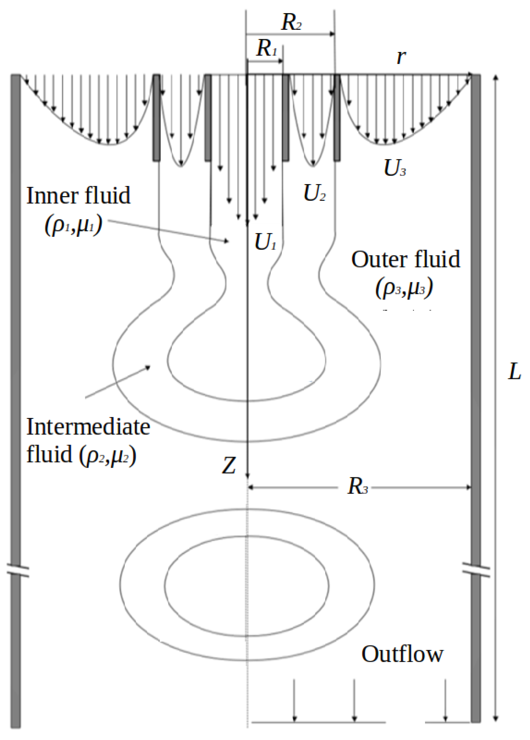
2. Formulation
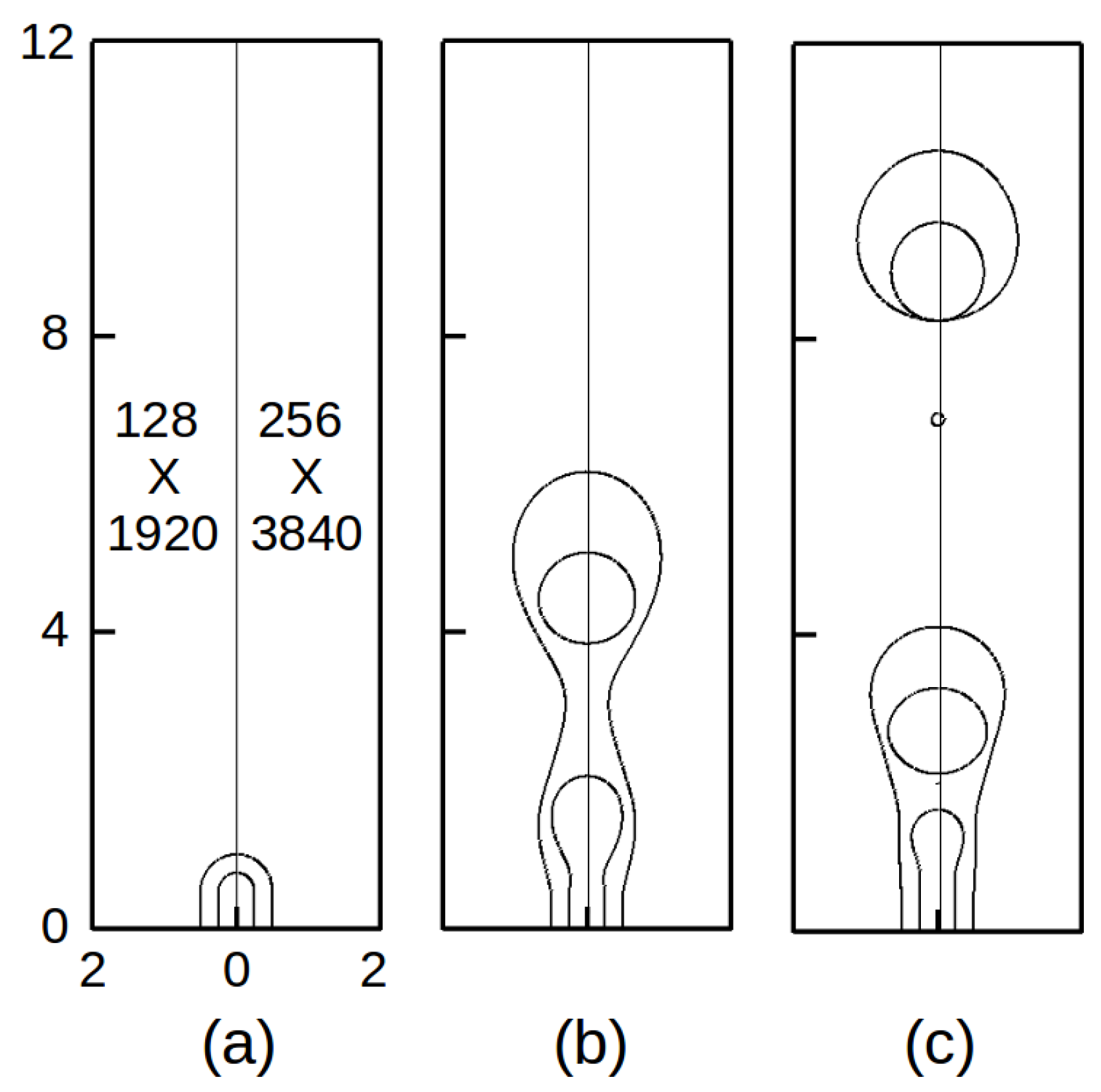
3. Numerical Method
4. Results and Discussion
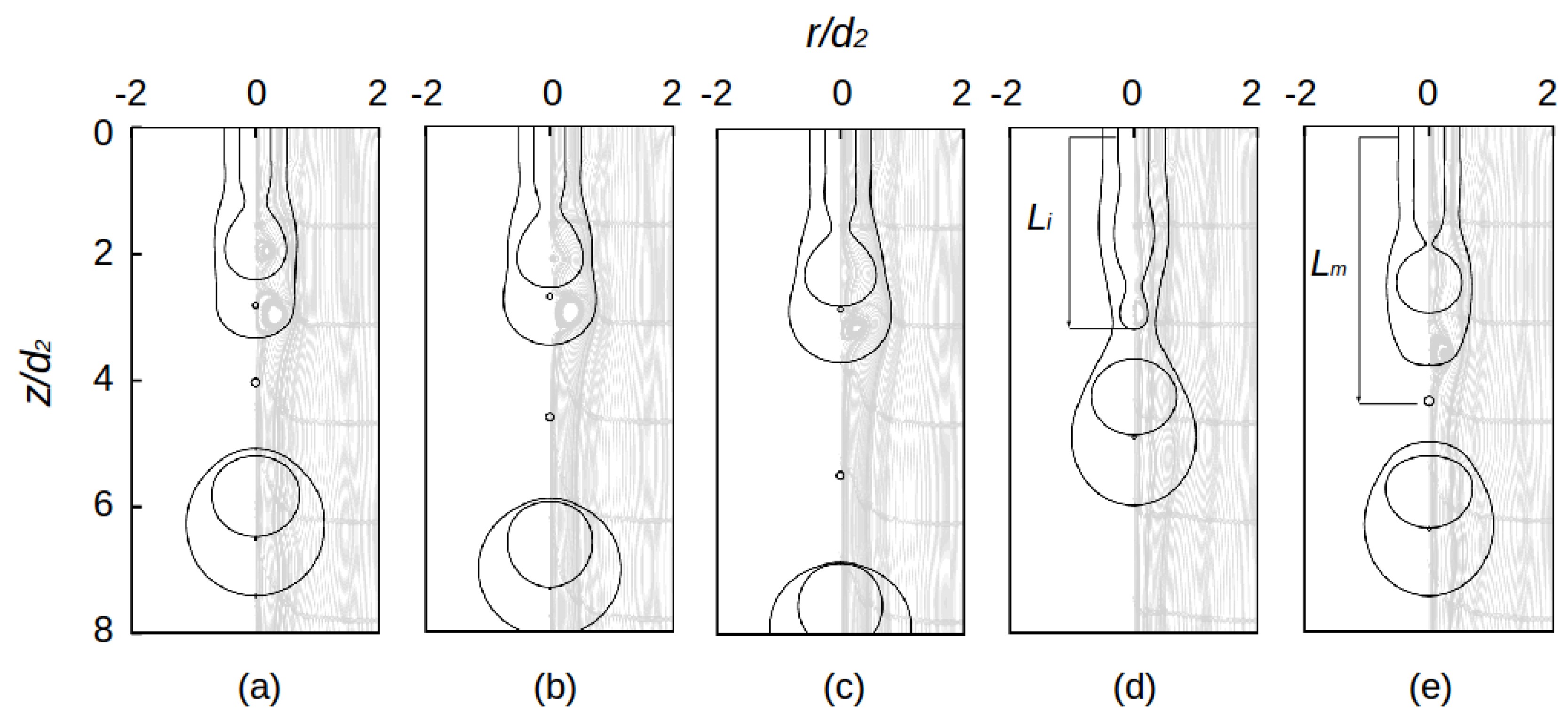
4.1. Baseline Case
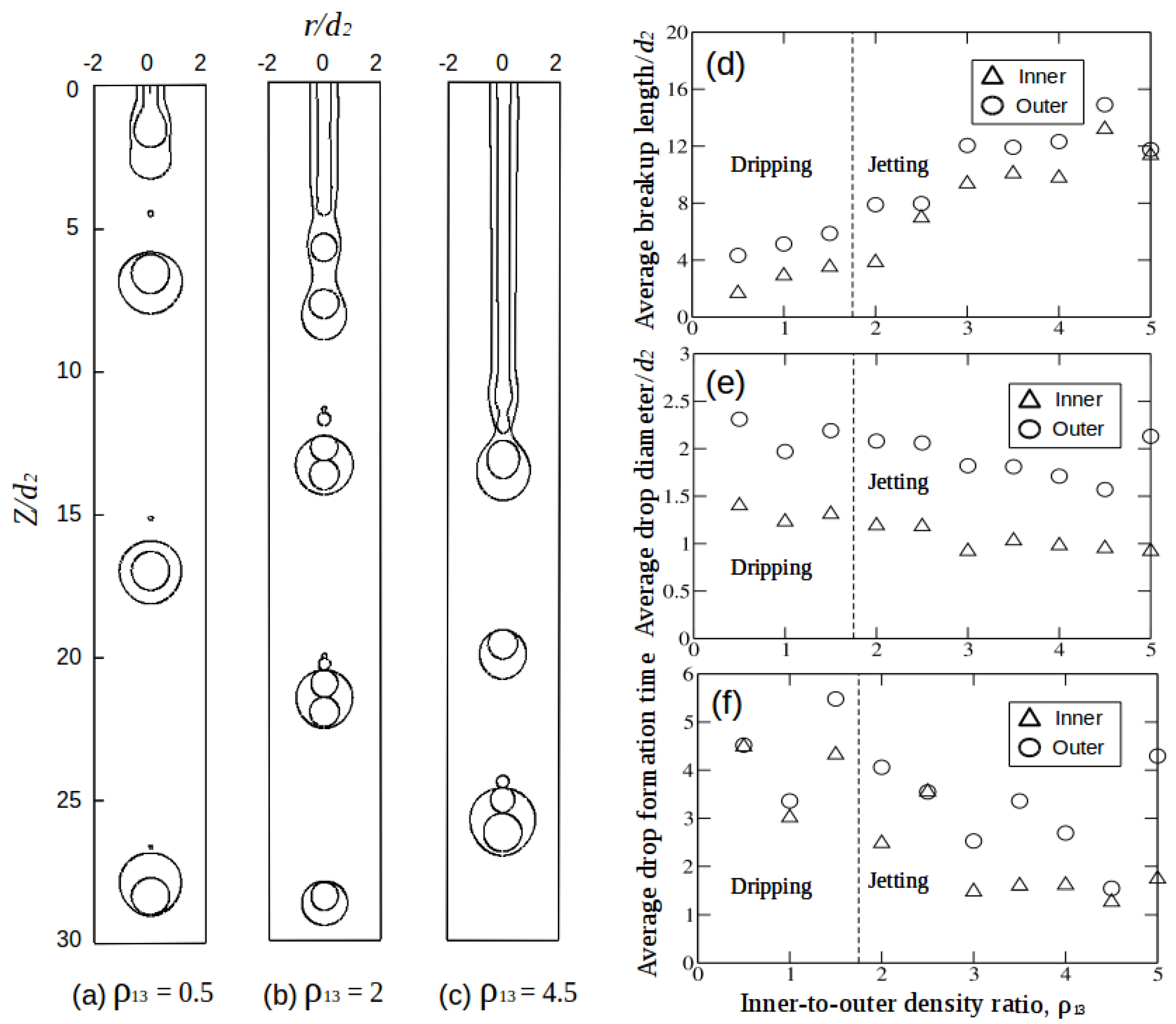
4.2. Effect of Inner-to-Outer Density Ratio
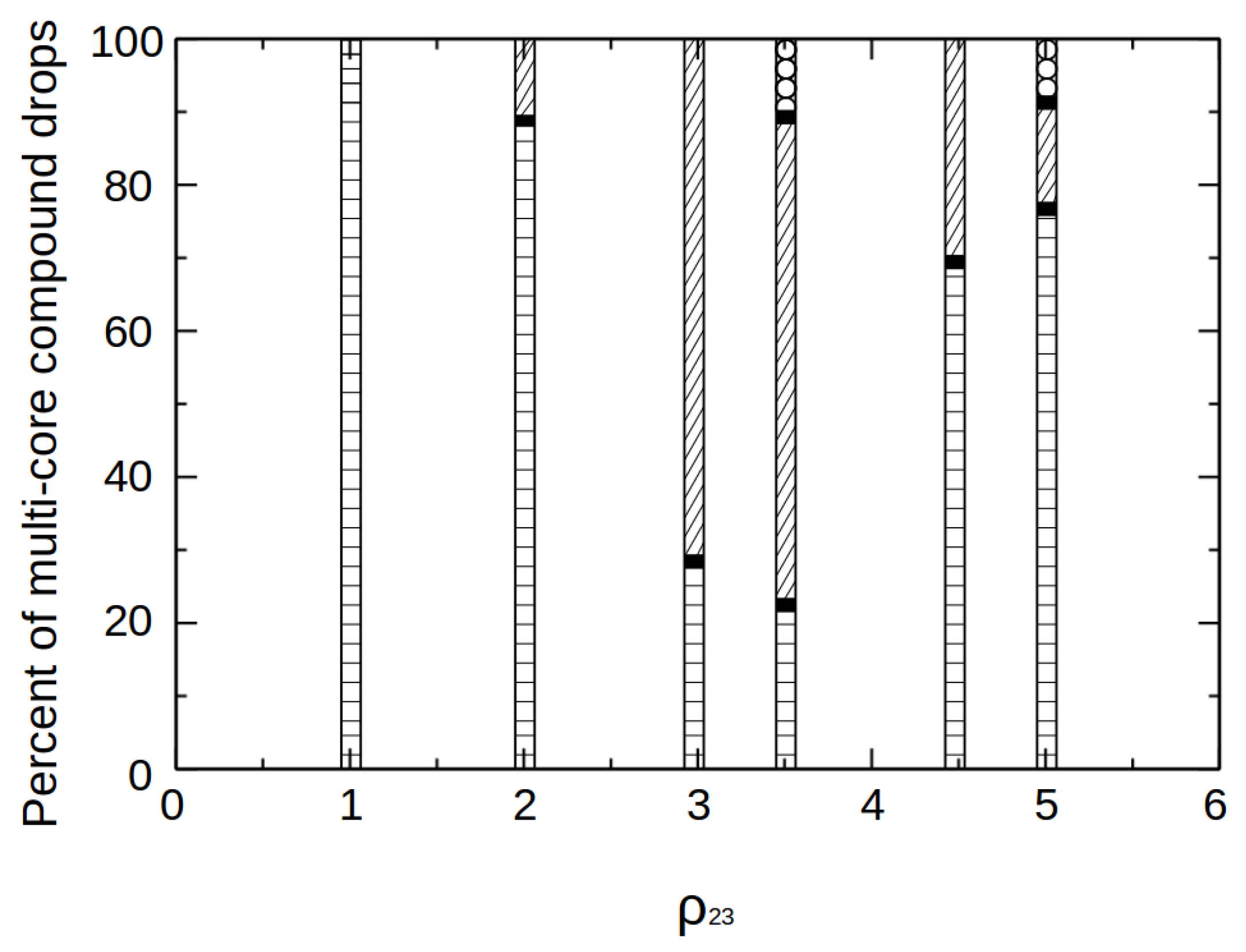
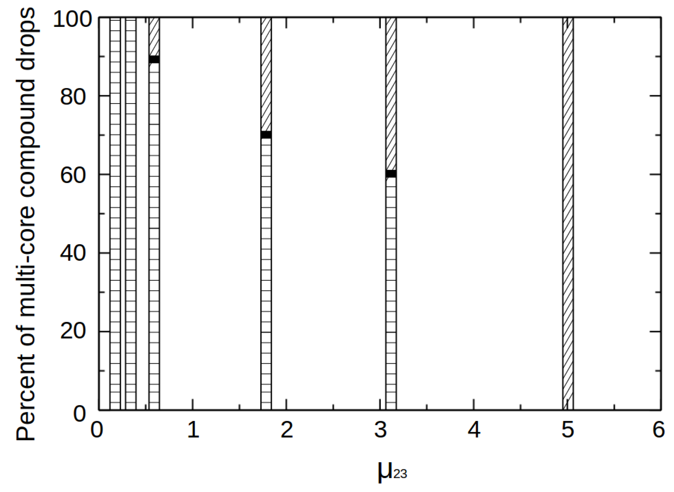
4.3. Effect of Intermediate-to-Outer Density Ratio (
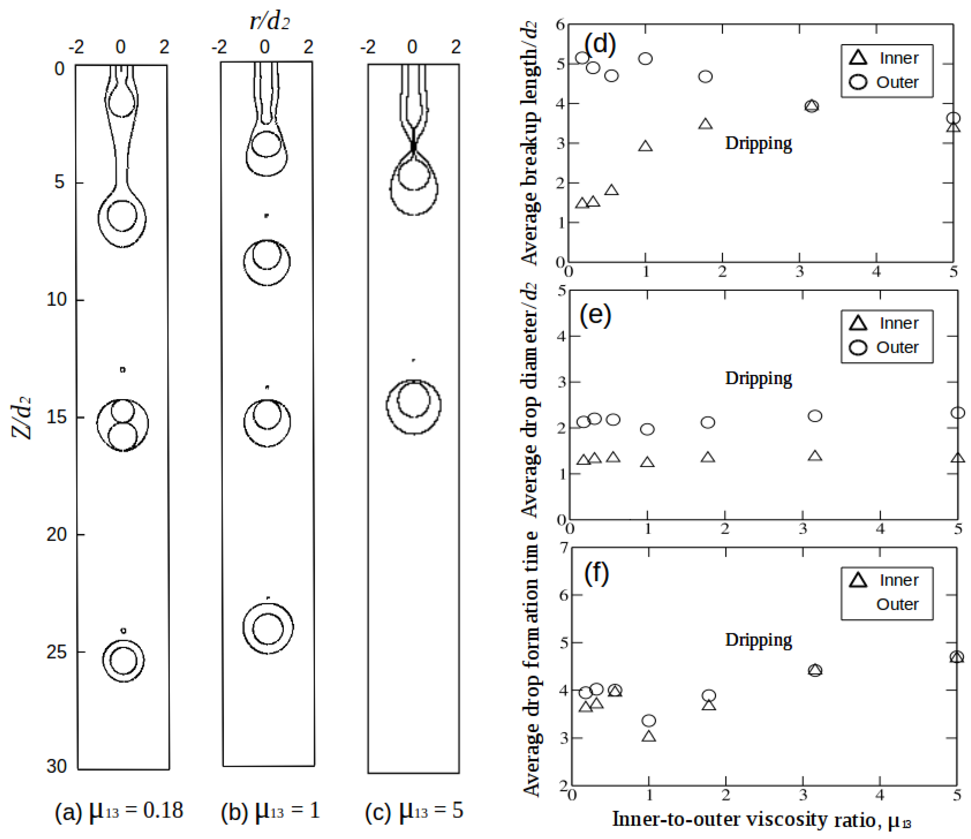
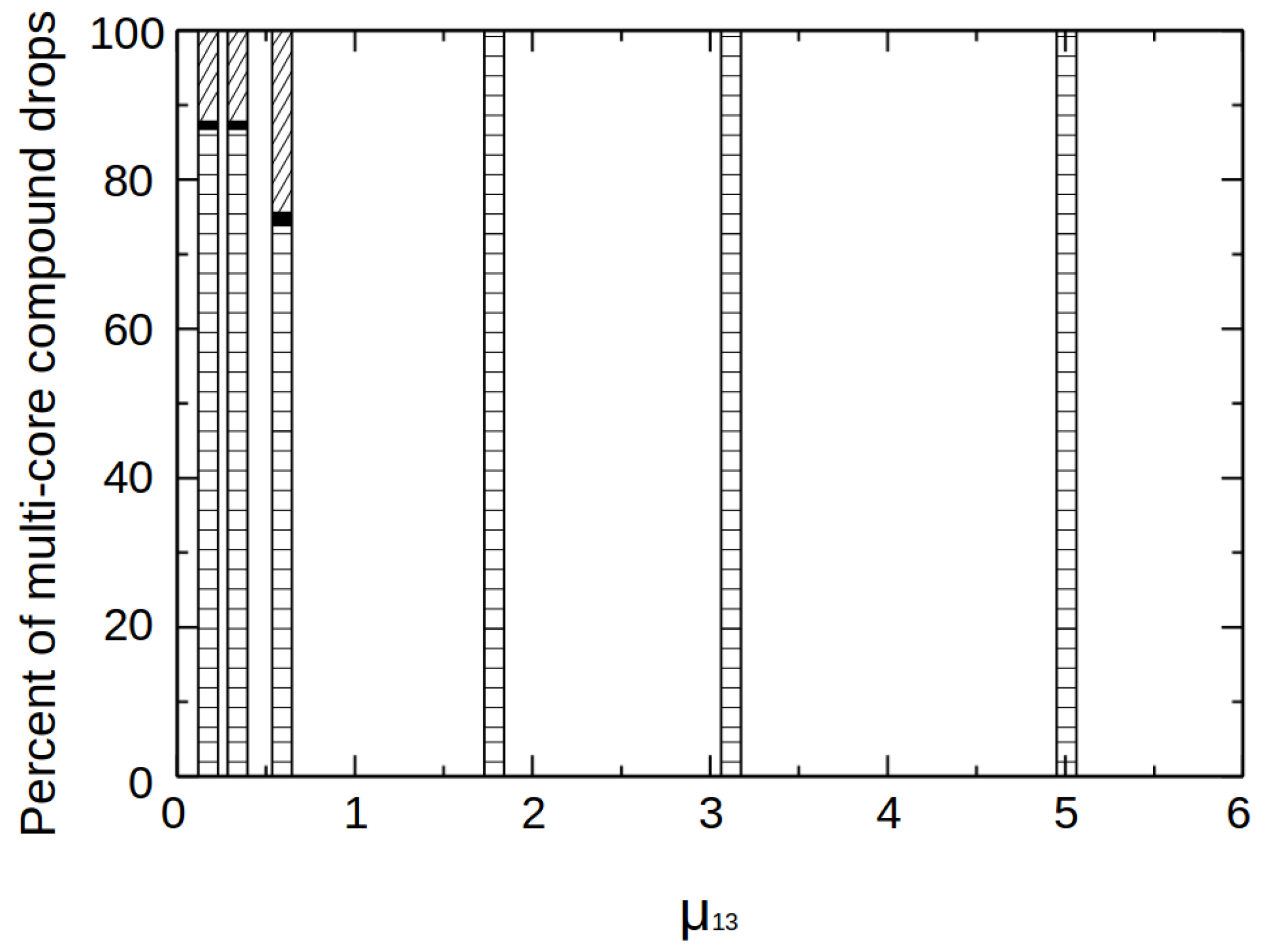
4.4. Effect of Inner-to-Outer Viscosity Ratio (
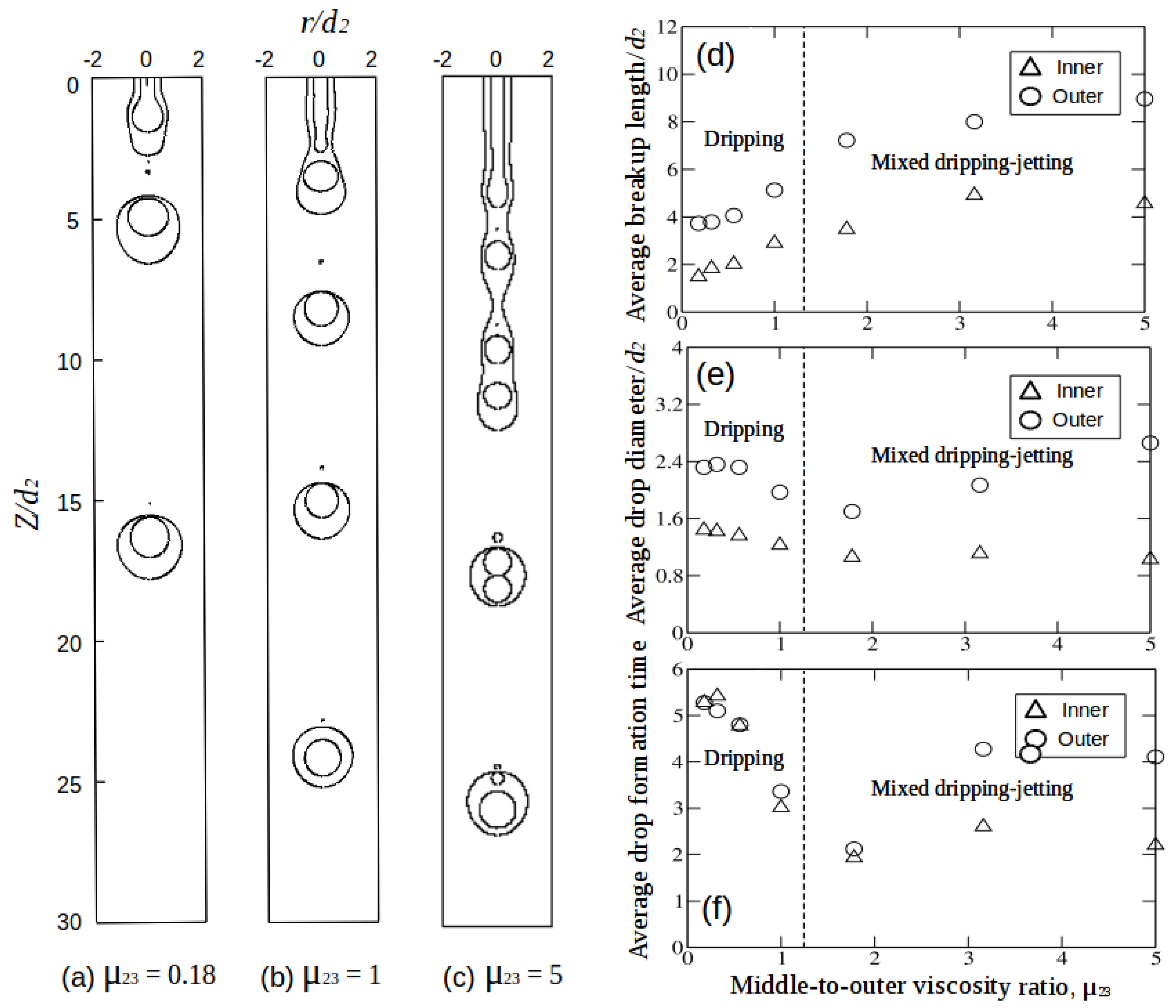
4.5. Effect of Intermediate-to-Outer Viscosity Ratio (
5. Conclusions
Supplementary Materials
Author Contributions
Funding
Acknowledgments
Conflicts of Interest
References
- Abate, A.R.; Thiele, J.; Weitz, D.A. One-step formation of multiple emulsions in microfluidics. Lab Chip 2011, 11, 253–258. [Google Scholar] [CrossRef] [PubMed]
- Denn, M.M. Continuous Drawing of Liquids to form Fibers. Annu. Rev. Fluid Mech. 1980, 12, 365–387. [Google Scholar] [CrossRef]
- Hertz, C.H.; Hermanrud, B. A liquid compound jet. J. Fluid Mech. 1983, 131, 271. [Google Scholar] [CrossRef]
- Shen, J. Experiments on annular liquid jet breakup. At. Sprays 2001, 11, 18. [Google Scholar] [CrossRef]
- Mathiowitz, E.; Jacob, J.S.; Jong, Y.S. Biologically erodable microspheres as potential oral drug delivery systems. Nature 1997, 386, 410–414. [Google Scholar] [CrossRef]
- Herrada, M.A.; Montanero, J.M.; Ferrera, C.; Gañán-calvo, A.M. Analysis of the dripping–jetting transition in compound capillary jets. J. Fluid Mech. 2010, 649, 523. [Google Scholar] [CrossRef]
- Andreas, S.; Alexiou, C.; Bergemann, C. Clinical Applications of Magnetic Drug Targeting. J. Fluid Mech. 2001, 95, 200–206. [Google Scholar]
- Rayleigh, L. On the capillary phenomena of jets. Proc. R. Soc. Lond. 1879, 29, 71–97. [Google Scholar]
- Chauhan, A.; Maldarelli, C.; Papageorgiou, D.T.; Rumschitzki, D.S. Temporal instability of compound threads and jets. J. Fluid Mech. 2000, 420, 1–25. [Google Scholar] [CrossRef]
- Subramani, H.J.; Yeoh, H.K.; Suryo, R.; Xu, Q.; Ambravaneswaran, B.; Basaran, O.A. Simplicity and complexity in a dripping faucet. Phys. Fluids 2006, 18, 1–13. [Google Scholar] [CrossRef]
- Vu, T.V.; Homma, S.; Wells, J.C.; Takakura, H.; Tryggvason, G. Numerical simulation of formation and breakup of a three-fluid compound jet. J. Fluid Sci. Technol. 2011, 6, 252–263. [Google Scholar] [CrossRef]
- Vu, T.V.; Wells, J.C.; Takakura, H.; Homma, S.; Tryggvason, G. Numerical calculations of pattern formation of compound drops detaching from a compound jet in a coflowing immiscible fluid. J. Chem. Eng. Jpn. 2012, 45, 721–726. [Google Scholar] [CrossRef]
- Vu, T.V.; Homma, S.; Tryggvason, G.; Wells, J.C.; Takakura, H. Computations of breakup modes in laminar compound liquid jets in a coflowing fluid. Int. J. Multiph. Flow 2013, 49, 58–69. [Google Scholar] [CrossRef]
- Nadler, J.H.; Sanders, T.H., Jr.; Cochran, J.K. Aluminum hollow sphere processing. Mater. Sci. Forum 2000, 331, 495–500. [Google Scholar] [CrossRef]
- Lee, S.Y.; Snider, C.; Park, K.; Robinson, J.P. Compound jet instability in a microchannel for mononuclear compound drop formation. J. Micromech. Microeng. 2007, 17, 1558–1566. [Google Scholar] [CrossRef][Green Version]
- Utada, A.S. Monodisperse double emulsions generated from a microcapillary device. Science 2005, 308, 537–541. [Google Scholar] [CrossRef]
- Kendall, J.M. Experiments on annular liquid jet instability and on the formation of liquid shells. Phys. Fluids 1986, 29, 2086. [Google Scholar] [CrossRef]
- Zhou, C.; Yue, P.; Feng, J.J. Formation of simple and compound drops in microfluidic devices. Phys. Fluids 2006, 18, 092105. [Google Scholar] [CrossRef]
- Suryo, R.; Doshi, P.; Basaran, O.A. Nonlinear dynamics and breakup of compound jets. Phys. Fluids 2006, 18, 082107. [Google Scholar] [CrossRef]
- Harlow, F.H.; Welch, J.E. Numerical calculation of time-dependent Viscous incompressible flow of fluid with free surface. Phys. Fluids 1965, 8, 2185–2189. [Google Scholar] [CrossRef]
- Tryggvason, G.; Bunner, B.; Esmaeeli, A.; Juric, D.; Al-Rawahi, N.; Tauber, W.; Han, J.; Nas, S.; Ja, Y.J. A front-tracking method for the computations of multiphase flow. J. Comput. Phys. 2001, 169, 708–759. [Google Scholar] [CrossRef]
- Homma, S.; Koga, J.; Matsumoto, S.; Song, M.; Tryggvason, G. Breakup Mode of an Axisymmetric Liquid Jet Injected into Another Immiscible Liquid. Chem. Eng. Sci. 2006, 61, 3986–3996. [Google Scholar] [CrossRef]
- Cramer, C.; Fischer, P.; Windhab, E.J. Drop formation in a co-flowing ambient fluid. Chem. Eng. Sci. 2004, 59, 3045–3058. [Google Scholar] [CrossRef]
- Pal, R. Rheological Constitutive Equation for Bubbly Suspensions. Ind. Eng. Chem. Res. 2004, 43, 5372–5379. [Google Scholar] [CrossRef]
- Scheele, G.F.; Meister, B.J. Drop formation at low velocities in liquid-liquid systems. AIChE J. 1968, 14, 9–15. [Google Scholar] [CrossRef]
- Rappa, B.E. Microfluidics: Modeling, Mechanics and Mathematics; Elsevier: Amsterdam, The Netherlands, 2017; pp. 745–754. [Google Scholar]
- Afzaal, M.F.; Uddin, J.; Alsharif, A.M.; Mohsin, M. Temporal and spatial instability of a compound jet in a surrounding gas. Phys. Fluids 2015, 27, 044106. [Google Scholar] [CrossRef]
- Homsy, G.M. Viscous Fingering in Porous Media. Annu. Rev. Fluid Mech. 1987, 19, 271–311. [Google Scholar] [CrossRef]
- Omocea, I.L.; Patrascu, C.; Turcanu, M.; Balan, C. Breakup of Liquid Jets. Energy Procedia 2016, 85, 383–389. [Google Scholar] [CrossRef]
- Zhang, D.F.; Stone, H.A. Drop formation in viscous flows at a vertical capillary tube. Phys. Fluids 1997, 9, 2234–2242. [Google Scholar] [CrossRef]


| 0.1–5 | 1–5 | 0.18–5 | 0.18–5 |
© 2019 by the authors. Licensee MDPI, Basel, Switzerland. This article is an open access article distributed under the terms and conditions of the Creative Commons Attribution (CC BY) license (http://creativecommons.org/licenses/by/4.0/).
Share and Cite
Bhagat, K.D.; Vu, T.V.; Wells, J.C. Formation and Breakup of an Immiscible Compound Jet with Density or Viscosity Stratification. Appl. Sci. 2019, 9, 4817. https://doi.org/10.3390/app9224817
Bhagat KD, Vu TV, Wells JC. Formation and Breakup of an Immiscible Compound Jet with Density or Viscosity Stratification. Applied Sciences. 2019; 9(22):4817. https://doi.org/10.3390/app9224817
Chicago/Turabian StyleBhagat, Kunal D., Truong V. Vu, and John C. Wells. 2019. "Formation and Breakup of an Immiscible Compound Jet with Density or Viscosity Stratification" Applied Sciences 9, no. 22: 4817. https://doi.org/10.3390/app9224817
APA StyleBhagat, K. D., Vu, T. V., & Wells, J. C. (2019). Formation and Breakup of an Immiscible Compound Jet with Density or Viscosity Stratification. Applied Sciences, 9(22), 4817. https://doi.org/10.3390/app9224817