1. Introduction
In structural vibration control, piezoelectric materials [
1,
2] have been used with regularity for a few decades. The ceramic perovskite (Pb[Zr
xTi
1−x]O
3, 0 ≤ x ≤ 1) is a piezoelectric material transducer called a PZT patch, which is bonded onto a mechanical structure to obtain a very efficient passive damping technique using an external resonant resistive-inductive circuit known as an RL shunt. Two versions of the parallel and series RL shunt circuits are presented in Yamada et al. [
3]. The series and parallel resonant shunts are equivalent in terms of vibration control performance, but the parallel RL shunt is less sensitive to the mistuning of the optimal resistance value. A synthetic inductor is based on a generalized impedance converter (GIC), which is well-known as a gyrator [
4]. The gyrator was used instead of a real inductor in the analog circuits era [
5] to implement low frequency RC filters. The drawbacks of a real inductor are related to the physical dimensions, residual resistance, and electromagnetic interferences. Synthetic inductors are also used for mechatronic applications [
6,
7,
8], as in the case of resonant piezoelectric RL shunt vibration damping. The most performant and frequently used circuits to implement synthetic inductors in mechatronic applications are Riordan [
9] and Antoniou [
10] gyrator circuits. The RL shunt damping technique is very sensitive to resonance frequency mistuning, and adaptive circuits [
9,
10] were proposed based on an additional piezoelectric sensor and a voltage-controlled synthetic inductor (VCSI). The analog VCSIs presented in the literature are based on a Junction Field Effect Transistor (JFET) [
11] or photoresistive opto-isolator [
12] used as a voltage-controlled resistor (VCR). These circuits controlled by an external voltage have the advantages of a wide range of resistance values but unfortunately have a nonlinear response. The vactrol (photoresistive opto-isolator) has an extended response time, a significant memory effect, and retains the advantage of optical isolation. Considering digital electronics, we can obtain equivalent behavior with previous analog VCSIs versions by using a digital potentiometer [
13] as a VCR. To avoid constraining the abovementioned VCSI based on analog circuits presented in literature, two new approaches have been used to implement VCRs based on (1) an analog multiplier and (2) an operational transconductance amplifier (OTA). The best achievement of this paper is related with the linear response of the resonant frequency to the voltage control in resonant piezoelectric RL shunt vibration damping.
This paper is organized as follows: In
Section 2, the classical Antoniou [
10] synthetic inductor circuit design and simulation results are presented. In
Section 3, two new circuits for a voltage-controlled synthetic inductor are simulated. The experimental results, comparative analysis, and mistuning effect of the VCSI non-linearity in RL shunt vibration damping are presented in
Section 4. Finally,
Section 5 concludes the paper.
2. Synthetic Inductors Circuit Design
In 1948, Bernard D. H. Tellegen [
4] proposed a two-port passive electrical network element as a kind of transformer in which the primary voltage is converted to a secondary current, and vice versa, as it is shown in
Figure 1. He called this device a gyrator because of a theoretical analogy with a flywheel (gyroscope).
Currently, the gyrator is mostly known as an active electronic circuit [
9,
10], which in a limited range of voltage, current, and frequency, works as an ideal gyrator based on a transconductance model given by the following equation:
where
v is the voltage source,
g1 and
g2 are transconductances and
C is the capacitive load.
First, the synthesis with active elements of the gyrator to implement efficient RC filters [
5] happened many years later as a result of the analog circuit’s innovation period. Significant progress was added by operational amplifier (op-amp) integrated circuits used in Riordan [
9] or Antoniou’s [
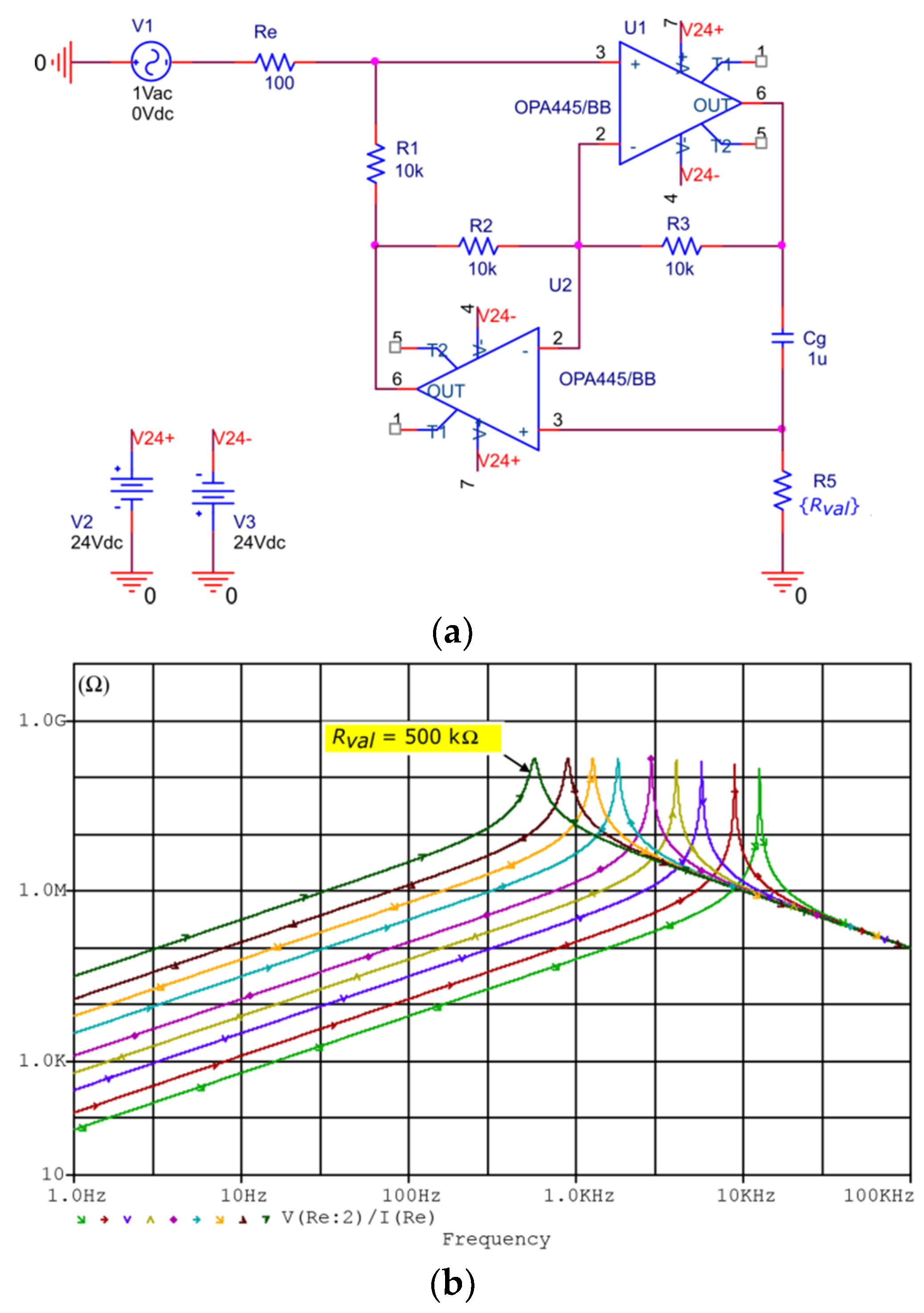
10] configuration that ensures a stable performance and a high-quality factor of the synthetic inductor. After some significant applications in analog processing of audio signals, a recent useful technological support was offered by gyrators in resonant piezoelectric RL shunt vibration damping. To demonstrate the real performance of synthetic inductor based on an Antoniou op-amp circuit, the PSPICE
® simulator (version 9.1, OrCAD
®, Cadence Design Systems, San Jose, CA, 95134, USA) has been used, as shown in
Figure 2a. To satisfy the real experimental condition, the high voltage FET-input op-amps (OPA445) are used in a parametric (
R5 =
Rval) circuit simulation. The circuit impedance simulation results shown in
Figure 2b confirm the limited bandwidth characteristic of the synthetic inductor with a self-resonance peak in perfect agreement with the behavior of the real inductor without residual resistance. For the low frequency range, the synthetic inductor is a very reasonable solution for very low mass-volume applications in dimensional agreement with a PZT patch used as smart materials in vibration damping. As is expected, the large frequency range can be easily controlled by changing the value of the
R5 resistor based on the following equation (symbols are defined in reference to
Figure 2):
In conclusion, the Antoniou circuit can be easily adapted based on Equation (2) for numerous real applications by changing the value of only two components Cg and R5.
In vibration damping experiments with an RL shunt to ensure very stable results for the Antoniou gyrator circuit, the best choice is
R1 =
R2 =
R3 =
R in the range of 1 kΩ to 10 kΩ. Considering the previous notation, the Equation (2) can be rewritten in simplified form as
L = R∙R5∙Cg. The stability of the Antoniou gyrator circuit has been experimentally demonstrated [
14] by using it in parallel with negative impedance converters (NIC).
4. Experimental Results and Comparative Analysis
For this study, an equivalent experimental setup with PSPICE
® simulations was used. The methodology was based on a network analyzer to measure the resonant frequency in equivalent RL shunt damping [
12] experiments. Based on Equations (4) and (6), the value of the VCSI inductance is a function of
, and in practice, can be easily modified using a new value for the capacitor. Some adjustments are also possible using new values for resistors
R1,
R2, and
R3, or only
R3 to ensure very simple tuning facilities. The static capacitance of the PZT patch and VCSI value of inductance are responsible for the resonance frequency of the electrical circuit
and the static capacitance of the PZT patch is the first element that has to be identified before starting the VCSI design. A schematic of the experimental configuration is shown in
Figure 5. The measurement system is built around a virtual vector network analyzer (SpectraPLUS-SC
®, version 5.3.0.2, Pioneer Hill Software LLC, Poulsbo, WA 98370, USA) to investigate a VCSI in parallel with a capacitor with an equivalent value of the static capacitance of the PZT patch (26 nF) used in the RL shunt vibration damping experiments. The virtual vector network analyzer was configured to measure a complex transfer function in 24 bits sampling format with a 0.732 Hz spectral line resolution. A white noise excitation signal is generated by software using a DDS (direct digital synthesis) algorithm. The USB interface used for data acquisition contained a performant coder-decoder circuit (CA0187-IAQ) boosted with a high impedance and very low noise amplifiers for both input channels. The excitation signal from the output of the coder-decoder circuit was passed through a power amplifier with a standard 50 Ω output impedance. An external power supply (+/− 24 V, HP-6236B) was used and voltage control was derived from it in a −10 V to 10 V range based on a precision voltage reference (AD584) and op-amps (OP27) in a voltage follower configuration.
The simulation and experimental results for both versions of the VCSIs are shown in
Figure 6a. To ensure a realistic comparison for both versions of the VCSI, an equal range for the voltage control was considered. For VCSI implemented with an AD633 analog multiplier as a VCR, the linear response to keep the error less than 0.5 Hz was obtained for the voltage control from −10 V to 2 V. In the case of a VCSI implemented with OTA LM13700 as a VCR, in the condition aforementioned, the linear response was obtained for the voltage control between −2 V to 10 V. For particular implementations presented in this paper, the frequency range was 8.4 Hz for the VCSI based on LM13700 and 8.9 Hz for the version with AD633. It can be considered that both VCSIs covered equal linear frequency domains for an equivalent voltage control range with a medium resolution of 0.72 Hz/V. With the experimentally validated linearity and its unique very high resolution, the new VCSIs analyzed in this paper outperformed the previous analog circuits [
11,
12] presented up until now in literature. From analysis of the residuals, for the identical voltage control range presented in
Figure 6b, it can be concluded that the VCSI based on AD633 had a better linearity in comparison with the LM13700 version. Both VCSIs had an equivalent frequency domain for identical linear voltage control ranges and met the condition of having a frequency deviation less than 0.5 Hz to produce with linear behavior. From the experimental point of view, the VCSI based on an analog multiplier (AD633) was more easily implemented using only a resistor mounted external to the integrated circuit.
Considering a mechanical structure with a PZT patch attached by it and
as the modal vibration frequency, the maximum vibration damping with an RL shunt method can be obtained for optimal value of the resistor and equal resonant frequency of the electrical circuit, i.e.,
. The resonant frequency mistuning effect in the RL shunt vibration damping has been intensive investigated in References [
2,
6] and adaptive tuning techniques have been proposed. The VCSI with a linear response for the RL shunt resonant frequency can be considered a big step forward as technological support toward implementing new simplified adaptive methods. By increasing the robustness of the RL shunt against mistuning, future integration of the method in more practical applications is ensured and these investigations are to be a constant research activity in smart materials and the intelligent systems community.
To demonstrate the capabilities of the new proposed VCSIs in vibration damping applications based on an RL shunt,
Figure 7 shows the simulation results of the mistuning effect due to the resonant frequency nonlinearity of the electrical circuit. In
Figure 7a, the simulation results for VCSI based on an analog multiplier is presented in accordance with two reference situations: an open circuit and perfect tuning where
.
Three extreme points of residual analysis, as is shown in
Figure 6b, were chosen for vibration damping simulation in this case: −10 V, −4 V, and 2 V. The mistuning effect of nonlinear behavior is very low with less than 1.84 dB depreciation of the vibration damping performance of the RL shunt.
The simulation results for the VCSI based on an OTA are shown in
Figure 7b in accordance with two reference situations: open circuit and perfect tuning where
. Based on the residual analysis, as is shown in
Figure 6b, three extreme points were chosen for vibration damping simulation in this case: −2 V, 4 V, and 10 V. Nonlinear behavior regarding voltage control induced a mistuning effect that involved a depreciation of vibration damping performance for the RL shunt of less than 1.15 dB in this case.
For both VCSI circuits, the nonlinearity regarding the voltage control induced a mistuning effect in an insignificant range and the circuits can be used with a very good performance for practical applications. In a very large bandwidth for the voltage control from −10 V to 10 V, the linearity of the VCSI version with an OTA used as a VCR was better in comparison with the VCSI based on an analog multiplier, as shown in
Figure 6a. The VCSI based on an analog multiplier was more practical from an experimental point of view and considering only limited voltage control range, it had a better linearity, as shown in
Figure 6b.
New adaptive and simplified techniques based on open or closed loop strategies can be imagined in the future to improve RL shunt robustness in the presence of uncertainty under cumulated effects induced by environmental temperature, materials aging, or modifications in the geometry of the mechanical structures. The well-known difficulties in tuning the multi-modal RL shunt [
6] for more than two modal vibration frequencies of mechanical structures can be avoided using VCSIs with a linear response of the RL shunt resonant frequency regarding voltage control.


