1. Introduction
In the last decade, soft robots have drastically expanded their domain in the medical field. Particularly, soft wearable devices (SWDs) are aid systems that merge robotics and wearable technology in order to overcome human disabilities [
1]. These systems are manufactured with materials that are characterized for their flexibility, adaptability, lightness and increasingly large deformations [
2]. These features allow comfortable structures that fit with the limbs and emulate joints motions.
SWD rehabilitation and assistance tasks have been mainly focused on regaining joints range of motion (ROM) through exercise routines. Furthermore, SWDs help patients to recover self-esteem and independence to execute the activities of daily living and act as a supportive aid for therapists [
3].
For example, Soft Exo-suits have been proposed for walking tasks [
4,
5] and knee rehabilitation [
6,
7]. Soft Exo-sleeves for shoulder [
8,
9], elbow [
10,
11], forearm [
12,
13] and wrist [
14] rehabilitation have been also reported. Moreover, soft exo-gloves (SEG) have been developed for hand rehabilitation and objects manipulation [
15,
16].
On the generation of SWD, one of the most important challenges is the development of soft actuators. Among several options, cable-driven and fluid pressurization have been mostly selected [
17,
18]. Important efforts have been made concerning the materials that improve the structure of soft actuators. For example, the use of elastomer [
19], composite materials [
20] or materials similar to human muscles [
21] that offer variable stiffness. 3D printing is highly used as a manufacturing process for soft actuators since it reduces costs and time delays [
22,
23].
During SWD evolution, several requirements have been attended to in order to enhance their efficiency, satisfy patients needs and guarantee their security. For instance, the authors of Reference [
24] establish that SEG performance is determined by the operation and usability conditions which refer to several system attributes such as actuation, materials, degrees of freedom (DOF) and manufacture processes, among others. Furthermore, in Reference [
15] a control unit is proposed to guarantee safe interactions between SWD, patient and environment.
SWD fabrication procedures have been diversified but sequential approaches are the most employed as has been stated in Reference [
24]. Overall, these methods are integrated by modeling, fabrication and validation (MFV) phases. In sequential approaches, based on general requirements, the engineering point of view prevails over the medical knowledge and experience. However, these approaches are not suitable for all patients since his/her clinical condition must be considered for SWD design, fabrication and implementation.
This paper proposes a design methodology which comprises the conception and manufacturing of SWD oriented to a specific necessity based on bottom-top methodologies (BTM) [
25,
26]. BTM principles have been already applied in automotive, military and aerospace industries [
27]. Similar structures have been proposed in References [
28,
29] for the design of manipulator robots. Therefore, this paper extends the application of BTM into the soft wearable devices field to produce a new methodology that goes from a particular solution to general cases. This extension of BTM represents the main contribution of this paper allowing the proposal of a modular technological platform for SWD diversification.
The proposed design methodology seeks to unify medical, therapeutic and engineering guidelines for research, development and innovation of SWD. It is highlighted that the research aspect includes clinical support about patient’s condition in order to identify his/her main necessity and define SWD constraints through concurrent engineering, instead of using general requirements as in MFV approaches. Concerning the development aspect, modeling and manufacturing tasks of EPM are addressed. Lastly, the innovation aspect is considered as a future objective of the proposed methodology in order to accelerate the transition between design concepts and available products.
The aforementioned methodology and technological platform will serve for future soft robotics developments. The design pathways could be diversified but the considerations involved in the methodology and platform are invariant. Both of them could be adapted to the development of grippers, artificial muscles, manipulators, mobilizers or any soft wearable device (hands, knee or ankle, for example).
This paper is organized as follows.
Section 2 provides a detailed description of the SWD methodology which includes three types of design criteria for their development and provides a modular platform which defines a family of SWD products. In
Section 3, this methodology is implemented on a case study for the design concept of an upper limb rehabilitation soft mobilizer called MOSAR (from Spanish: Mobilizador Suave para Asistencia y Rehabilitación).
Section 4 discusses the advantages and opportunity areas of the proposed design methodology. Conclusion and future work are reported in
Section 5.
2. Design Methodology
The design of soft devices must guarantee a safe operation since these systems could be in contact with patient’s skin, tissues, organs or surgical tools [
30]. To couple a SWD to human limbs to operate intuitively as a whole system, with easy donn-doff, without obstructing natural motions and nor causing deterioration of the patient is still a challenge.
To face these challenges, MFV strategies consider technology to assess the physical condition of the patient. For instance, brain activity is mostly evaluated by electroencephalography and magnetic resonance imaging tests [
31] while muscle impairment and joints ROM assessment use EMG (Electromyography) tests [
32].
The field of soft wearable devices requires new methodologies that empathize with patients’ needs to analyze their physical condition and not only to cope with people demands. The methodology proposed in this paper combines MFV phases with BTM principles in order to create a patient-centered design whose respective solution is scaled, depending on patient’s limitations, to reach a general procedure.
This new methodology proposes the conception and manufacturing of soft wearable devices based on integral assessment about patient health (medical technology and experts’ feedback). Basically, it seeks to unify medical, therapeutic and engineering guidelines for the continuous improvement of:
Research. It starts with a custom analysis about patient’s clinical condition considering specialists’ criteria and available medical technology. From these assessments, valuable information is obtained to define constraints and operation conditions prior to SWD design.
Development. It encompasses SWD design to obtain a virtual model, its manufacture and control. This paper proposes reverse engineering as a CAD tool to model and obtain a morphological reference of the target limb for the design concept of SWD.
Innovation. It relies on the reverser engineering approach to accelerate the manufacturing and implementation of SWD systems as available products.
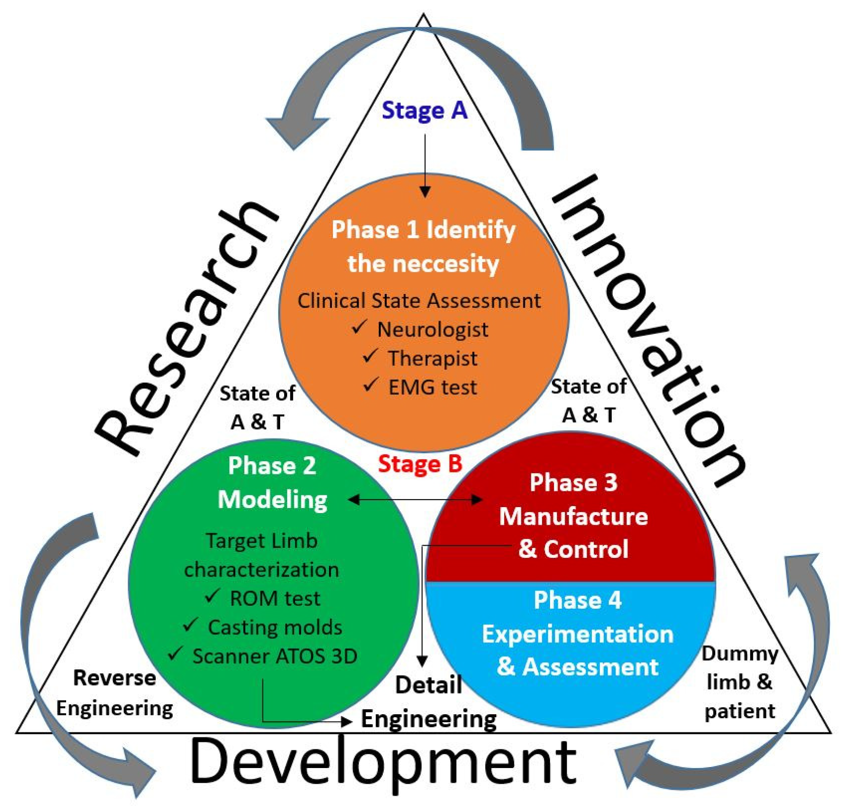
The interaction between research, development and innovation is illustrated in
Figure 1, where the next 8 aspects are highlighted.
A continuous improvement action is illustrated by arrows in a counter-clock wise direction.
Innovation and development share information and actions in both senses.
The clinical state of a patient is assessed by a neurologist, therapist and EMG tests.
Development is based on the reverse engineering approach.
The target limb characterization involves ROM testing, casting molds and 3D scanning techniques for its 3D digitalization.
During the development, detail engineering is applied for changes on the modeling and manufacturing phases.
Experimental validation is carried out, firstly, on a dummy limb and later on the patient.
A continues review of the states of the art and the technique (A&T) are considered on the process.
To achieve the objective of this methodology, it is divided into two stages (A and B) and four phases (1 to 4). The methodology is integrated by 29 steps distributed as it is shown in
Table 1 and detailed in
Figure 2. The description of these phases and steps is provided in the following paragraphs.
2.1. Phase 1: Identification of the Necessity
To start off a soft wearable device design based on the proposed methodology, the target pathology must be defined. No matter the SWD application, a patient must be available (Step 1) in order to furnish this potential patient with the developed device to improve his/her quality of life. It is highly recommended to make patients feel confident to collaborate on the project from beginning to end.
The clinical condition of the patient (Step 2) is determined in order to identify the primary need (Step 3). Therefore, motor dysfunctions, physical condition and available ROM must be assessed to clearly define the main problem of the patient to merge medical technology and experts’ collaboration. The next three types of assessments are needed to propose an initial solution and to choose the correct SWD task:
Neurologist will give a valuable diagnosis about patient disease, physical condition and brain disorders (Step 4).
Therapist assesses impaired joints and muscles that need prompt rehabilitation. This advise will define the proper system’s ROM to overcome the motor dysfunctions (Step 5).
EMG testing will bear out the two previous diagnosis and pinpoint the electrical motor response of each target muscle (Step 6).
These results obtained from the previous assessments will define the available patient’s functional ROM and SWD constraints in order to enhance its operation resulting in an improvement on the patient’s condition. This assumption is based on the principle establishing that rehabilitation exercises on impaired joints will stimulate the muscles while the brain relearns these motions again [
33].
A literature review is proposed to analyze the states of the art and of the technique (Step 7) to find out related options and techniques that are already validated, as well as new trends to identify opportunity areas and alternative solutions. This methodology suggests a selection of at least five core references that define the design bases to cope with SWD target task and support the research (Step 8).
2.2. Phase 2: Modeling
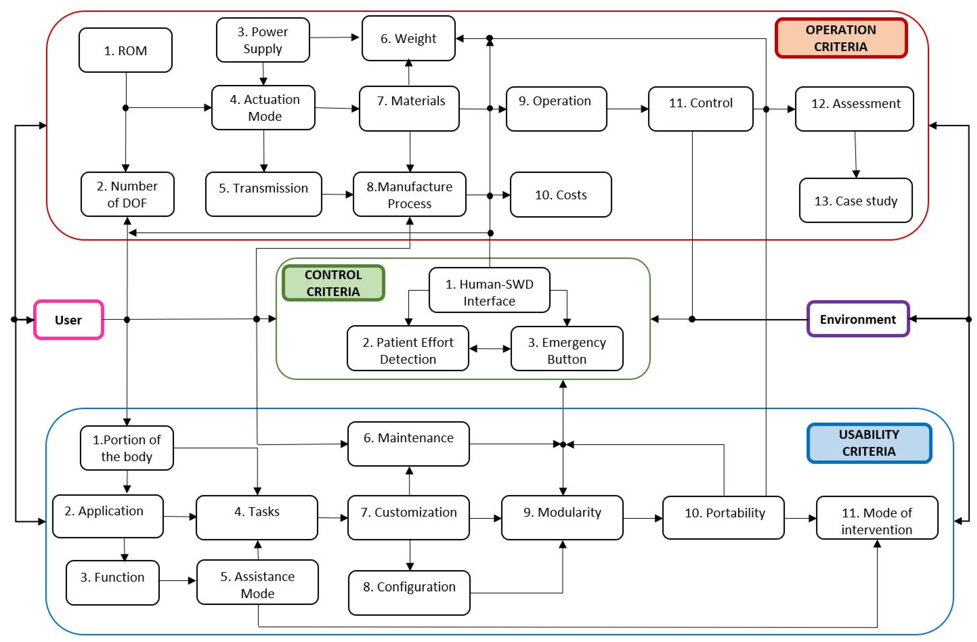
After compiling the information regarding the physical condition of the patient and defining the SWD objective, the modeling phase can initiate. This second phase represents the starting point for EPM conceptual design with the definition of the SWD design criteria (Step 9) based on SEG criteria which are established in References [
15,
24]. Thus, SWD design is integrated by mobility, usability and control criteria as it is portrayed in
Figure 3. All these criteria interact between them in order to allow researchers to build functional SWD systems for different applications.
The following usability criteria are oriented to emphasize the medical attributes of the system to incorporate current technology and expertise of therapists and neurologists.
Selection of the impaired portion of the body
Definition of the application (pathology)
Identification of the function (rehabilitation or assistance)
Establishment of the associated tasks (movements)
Selection of the assistance mode (passive or active)
Maintenance
Customization
Configuration (open or closed) design
Modularity
Portability (home rehabilitation)
Mode of intervention (unilateral or bilateral)
The mobility criteria, incorporated in the proposed methodology, are related to enhancing flexibility, compactness, ergonomics, wearability, payload capacity and lifespan of the system. Moreover, these criteria seek to guarantee SWD functionality in such a way that the patient can feel confident with the system and are provided below.
Definition of joints ROM based on impaired limbs
Definition of the number of DOF per joint
Definition of the power supply (pneumatic, hydraulic or electric)
Establishment of the type of actuation
Selection of the type of transmissions (if necessary)
Definition of the maximum weight
Selection of materials
Definition of the manufacturing processes
Operation tests
Costs analysis
Synthesis of a control strategy
Performing of assessment tests
Evaluation of the case study
Control criteria must provide safe interactions between SWD and patients even under unexpected disturbances. To do so, closed-loop control strategies are employed to minimize errors and guarantee stability [
34]. These criteria are:
Human-SWD interface to control actuators
Detection of patient’s effort (EMG)
Presence of a safety button for emergency stops
Depending on the mathematical model and on the desired performance of the SWD, the closed-loop control strategy will be developed. Reported values of pressure [
10], torque [
35] or payload capacity [
36] can be considered as reference for the associated control strategy.
This methodology proposes to measure the functional ROM values at each joint of the patient (Step 10) and compare them to normal healthy ROM to determine the operational ranges of the SWD depending on the joints’ impairment. A manual or electrical goniometer can be used along with therapist’s assistance to measure the patient’s joints ROM.
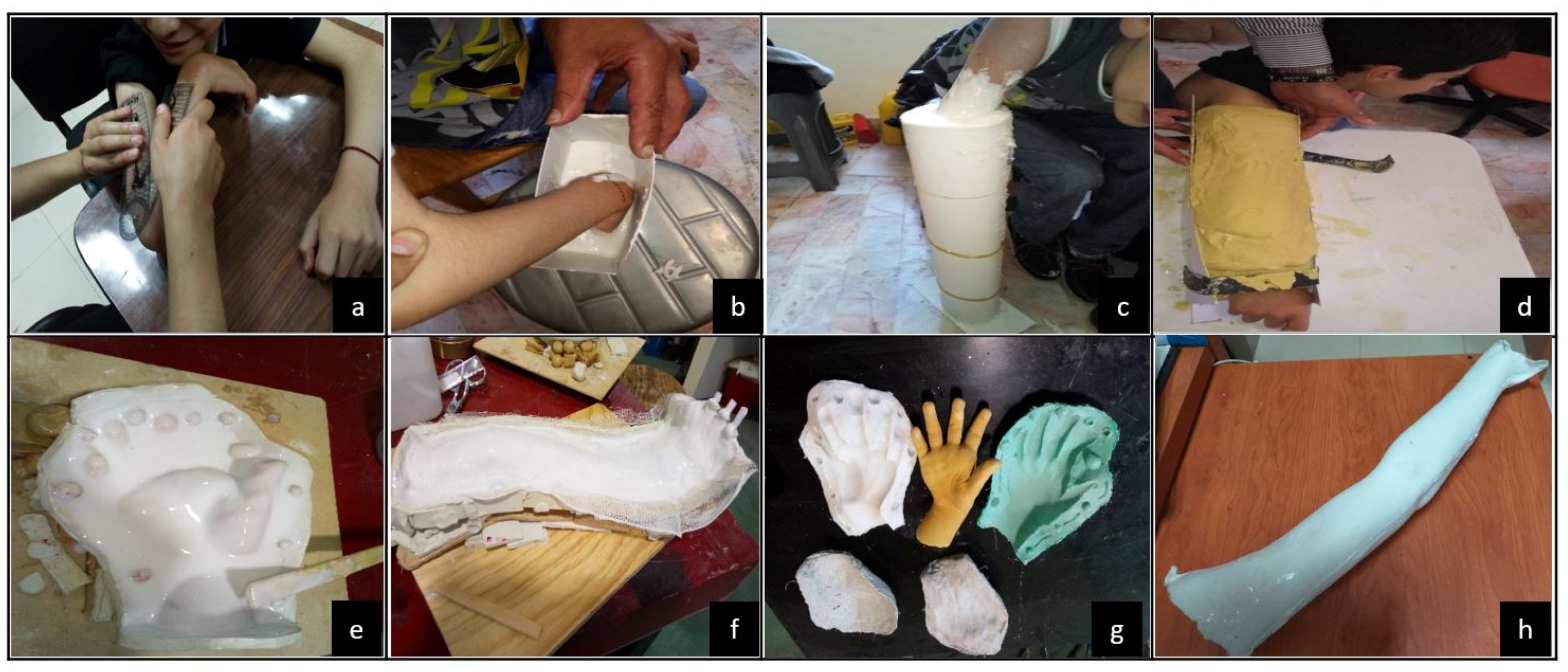
The design concept is developed through reverse engineering, firstly by a casting model from the impaired limb (Step 11) to gather the patient’s anatomical information and then, to obtain a silicon model (dummy limb) for practical and safe handling which will serve as a morphological reference for future assessments.
The reverse engineering tool will consider natural morphology to know how the joints are affected and obtain a skeleton reference frame for a customized SWD design concept. Additionally, the reverse engineering approach could diminish the design time between development and innovation for future SWD products.
Development continues with a 3D digitalization of the dummy limb (Step 12) using a 3D scanner. This computational model is the parameterized reference for SWD design. The 3D scanner handling requires a straightforward training depending on the scanner type, the associated software, the number of cameras and their calibration procedure.
During the mentioned scanning process, several shots should be taken around the dummy limb until the target area is completely covered depending on the scanner’s capabilities and the dummy limb’s complexity. Otherwise, the dummy model must be divided into several views depending on its shape and size. Then, all shots are merged to obtain the whole dummy limb.
At the end of this step, the projection of a scanned figure is converted into a mesh model which generates an initial graphics exchange specification file or a stereolithography 3D file to be manipulated on a CAD software to complete the design concept of the EPM.
System’s constraints are then identified (Step 13) and the attributes of the SWD could be characterized (Step 14) to control its functionality based on these constraints: anthropometric ranges, number of DOF, specific ROM, tackled joints and muscles, materials, actuation type, torque values, geometrical parameters of the actuators and power supply values, for instance.
The next step consists in doing a brainstorming process to generate several ideas of the EPM design concept (Step 15) whereby evaluation and selection of these proposals should be considered. The methodology continues with the modeling task starting with a virtual model (Step 16). This CAD model is used to analyze the effect of aligning its components to the patient’s natural joints on the digitalized dummy limb representing the basis for manufacturing processes.
A mathematical model can be developed (Step 17), as an approximation of the physical system, to analyze theoretical behavior of the SWD. Additionally, References [
36,
37] suggest that mathematical models and finite element method (FEM) analysis could be included to support the kinematics of SWD systems and their components endurance, respectively. Kinematics or dynamics calculations and stability analyses are examples of the use of this model to support its experimental validation. A closed-loop control could be required depending on the application (Step 18).
2.3. Phase 3: Control and Manufacturing
If a control law must be synthesized (Step 19), the control strategy design goes hand in hand with the mathematical model in order to reduce the error between the reference and output of the system. With a defined closed-loop control law or in open-loop contexts, numerical simulations (Step 20) are performed to analyze the aforementioned theoretical behavior.
The control interface of SWD will define the communication between patient, SWD and environment. This procedure ensures safe operation but depends on the actuation type and required precision.
Prior to the manufacturing of a SWD, theoretical (from the mathematical model) and virtual (from the CAD model) behaviors must be assessed (Step 21). The CAD model can use the data obtained from numerical simulations to compare the virtual behavior with the theoretical one.
Once the behavior of the SWD is validated, geometric dimensioning and tolerancing (GDT) are specified together with materials, surface finishing, tools and manufacturing processes, among other aspects, during the detail engineering design (Step 22).
Phase 3 continues with a review of the aforementioned criteria in order to guarantee their fulfillment (Step 23). If all the requirements are met, an experimental physical model is approved and can be manufactured (Step 24). Otherwise, the design concept must be analyzed (see step 15). This cycle continues until the EPM satisfies mobility, usability and control requirements. It is highlighted that the EPM corresponds to the SWD that will be tested.
SWD manufacturing focuses, mainly, on actuators. The SWD actuation could be done by fluid pressurization or cables. Conventionally for fluid pressurization, pneumatic actuation has been used for inflatable structures, pneumatic artificial muscles (PAM) and fluid elastomer actuators (FEA) which also used hydraulic energy [
30]. Regarding cable actuation, the designs have been diversified with dielectric elastomer actuators (DEA), electro active polymers (EAP), shape memory alloys (SMA) or tendon and muscle wires [
38].
Materials selection is crucial to obtain the desired actuators trajectories since actuators represent the core component for driving the SWD. For both types of actuation (fluids or cables), the materials selection include polymers, fabrics, composites, shape memory polymers (SMP), silicone, neoprene, elastomers and thermoplastic polyurethane (TPU) [
39].
Additive manufacturing as 3D printing, SLT techniques such as continuous liquid interface production (CLIP) or digital projection lithography (DPL) are mainly used in SWD fabrication [
23]. Other processes include shape deposition modeling (SDM) [
40], fused deposition modeling (FDM) [
41], laser sintering, direct ink writing, inkjet printing, inverse flow injection, bonding, thin film, inclusions or reinforcement. Detailed information concerning SWD manufacturing techniques can be consulted in Reference [
42].
For example, in the pneumatic actuators’ fabrication, FEA includes 3D printing molds and a casting process using elastomer materials followed by air extraction under vacuum conditions and the use of ovens to accelerate the curing process [
43]. Reported FEA designs include elastomer winding for fiber reinforcements to enhance support [
10]. PAM actuators are commercially available and soft inflatable TPU bladders are cut with laser, sealed with heat and then sewn [
44].
2.4. Phase 4: Experimentation and Assessment
With an EPM manufactured, experimental tests can start in phase 4. The aforementioned control strategy runs on the tangible SWD with the corresponding sensors, actuators and electronic components. Firstly, therapists evaluate the performance of the SWD on the dummy limb (Step 25). This testing bench provides data under different conditions of pressure, force, torque or ROM. If this assessment is approved by specialists, the SWD can be tested on the patient (Step 26). However, if any of these evaluations fails, the detail engineering design must be reviewed (see step 22) in order to generate an enhanced EPM. This cycle continues until the therapists grant their approval to proceed with the therapy of the patient using the SWD (Step 27). At this moment, the SWD operation is under the therapists’ supervision who define the rehabilitation protocol to evaluate patient’s recovery.
In this methodology, the satisfaction of medical devices standards such as ISO 13485 or FDA 821 can be considered from step 9 to step 24. This concentrated information (Step 28) is required to evaluate the technology readiness level (TRL) (Step 29) of the developed soft wearable device as in aerospace products [
45]. It is worth mentioning that every phase of this methodology includes a check list in order to validate it before moving on to the next phase. This will help to avoid reworks or wasting time.
Figure 4 summarizes the relationships between the design criteria and the described four phases.
2.5. Technological Platform of SWD
The described methodology seeks the generation of SWD as potential commercial products. Hence, this paper combines the aforementioned design criteria and implements the principles of Reference [
26] to create a technological platform. The SWD modular platform can be seen as a set of technological data that open a range of possibilities for developing and diversifying soft wearable devices for lower and upper limbs depending on the target solution.
In this modular platform, more than 50 SWD products identified when considering only six of the 27 design criteria that were established in
Section 2: function, assistance mode, portion of the body, DOF, joints and actuation as it is shown in
Figure 5. The type of actuators is crucial for driving the soft wearable device and depends on the requirements. However, this platform is not limited, more design criteria could be added in order to characterize a particular SWD.
The platform is integrated by eight exo-products, four for the upper limbs (shoulder pad, sleeve, glove and jacket) and four for the lower limbs (short, knee pad, ankle pad and pants). Every type of these wearable products is determined by the physical condition of the patient. For instance, people who suffer from diplegia only need a SWD for lower limbs (exo-pants). Likewise, this product family includes an exo-suit, with the eight mentioned exo-products, that is designed for quadriplegic patients. Nevertheless, the more number of tackled joints, the more difficult the SWD control.
The number of potential products
N is determined from the number of DOF
n to be combined using Equation (
1). For example (see
Figure 5), the hip joint depends on three DOF (Inter-Extern Rotation, Abduction-Adduction and Flexion-Extension). This combination generates seven products. An Exo-Short can be designed based on the hip, on the knee or on both joints, generating three products.
3. Methodology Implementation: The MOSAR Case
The SWD methodology that was presented in
Section 2 is implemented on the development of the MOSAR device. This SWD is an exo-sleeve (see
Figure 5) developed for the upper limb rehabilitation of a 10 years old boy with right paretic side. This section is focused on describing phases 1 and 2 of the proposed methodology until the generation of a virtual model (see step 16).
3.1. Phase 1: Identification of the Necessity
To start with the MOSAR development, assessments from a neurologist and a physical therapist, together with EMG tests, were carried out on the patient to evaluate his clinical condition, as follows.
Neurologist’s diagnosis. The specialist confirmed that hemiplegia on the right side of the patient was caused by a perinatal stroke that affected the left hemisphere due to the lack of oxygen. This specialist also reported that hemiplegia is currently on a chronic phase and the patient presents intellectual disability. Furthermore, patient’s muscles are still functional but spastic. The neurologist recommends arm, hand and face rehabilitation to stimulate the cortex since they have the highest mobility impact. Additionally, psychological and pedagogical assistance are recommended to improve his cognitive skills.
Therapist’s examination. During this assessment, the patient was identified to have problems to walk since the patient drags his right leg. It was also diagnosed that the patient’s right upper limb presents more muscular atrophy than the impaired lower limb due to the lack of use. Several assessments were performed to identify critical joints in the impaired upper limb. The therapist asserted that the patient does not present stiffness yet. However, his elbow, forearm and wrist joints present high levels of spastic hypertonia due to his minimal use causing clenched fist deformity. The specialists highly recommended urgent rehabilitation of the upper limb proximal segment (the right arm) to increase the work space of the patient prior to starting with manipulation tasks. Otherwise, the ROM will be still limited for executing activities of daily living.
EMG tests. The therapist defined to measure the electrical activity of following muscles: biceps, triceps, pronator, supinator, wrist flexor and wrist extensor to evaluate the ROM of elbow, forearm and wrist. As it can be observed in
Figure 6 the impairment was more severe at the proximal segment than at the distal one since the child has natural elbow flexion and forearm pronation. Elbow extension and forearm supination are absent. Also, flexion activity was reflected at the wrist due to its over flexed position. Ulnar and radial deviations along with fingers flexion-extension motions were nor detected even when the muscular activity of the associated muscles were measured.
These assessments match with the well known hemiplegic clinical condition characterized by (1) a fallen and protracted shoulder, (2) an inward rotated arm attached to the trunk, (3) a flexed and over pronated forearm and (4) a clenched fist [
46].
After the case study was analyzed, two contexts were identified: (a) to mobilize the elbow-forearm-wrist region or (b) to mobilize the hand for object manipulation. According to the results from three previous assessments, elbow and wrist were identified as critical joints that need to be, urgently, rehabilitated in order to prevent joint stiffness and improve hand mobility. It was concluded that it was not feasible to start a rehabilitation process at the distal segment since the proximal one has no mobility. Besides, the muscles acting on the distal segment are inserted to the proximal one.
Hence the MOSAR, endowed with four DOF, focuses on the mobilization of the joints by exerting flexion-extension at the elbow, pronation-supination on the forearm and flexion-extension along with ulnar-radial deviations at the wrist of the patient. The rehabilitation protocol associated with these movements will help to regain strength, decrease spasticity and prevent joint stiffness. MOSAR is aimed to reproduce this rehabilitation protocol in an assisted strategy.
Moreover, the increase of the ROM at the proximal region would benefit the distal segment for further manipulation tasks. Manipulation assessment, performed by the therapist, revealed that the patient is able to open-close his fist. He can grab objects with low precision in a restricted area due to his medical condition. Additionally, the MOSAR system seeks to provide a new therapeutic approach that increases the use of the paretic upper limb of the patient.
To finish phase 1 of the methodology, a review of the states of the art and of the technique related to upper limb rehabilitation at elbow, forearm and wrist was done. From this research, five core references were identified with similar works [
8,
10,
11,
12,
13]. These five SWD were taken as a reference for the conception of the MOSAR system.
3.2. Phase 2: EPM Modeling
Once the MOSAR task has been identified, the workplan continues with the EPM modeling phase following the flow diagram for a soft wearable device from
Section 2 (See
Figure 2). Phase 2 starts with the identification of each segment body mass of the upper limb [
47], torques [
35] and the values of ROM, forces, pressures and motions that have been reported from elbow [
10,
11] and forearm-wrist [
12,
13]. This information constitutes the basis to support the aforementioned design criteria.
Table 2 includes the respective values required for the development of the MOSAR system. Nonetheless, not all the data are provided in literature.
Therefore, in order to achieve upper limb rehabilitation and define MOSAR constraints, anthropometric upper limb lengths of the patient were measured. In addition, functional ROM (active and passive) of elbow (flexion-extension), forearm (pronation-supination) along with wrist (flexion-extension and ulnar-radial deviations) were quantified with a manual goniometer. These two activities were carried out under therapist supervision to evaluate patient’s current manipulation abilities and define MOSAR’s dimensions and ROM.
Table 3 reports the ROM values of the patient.
During ROM examination, the patient was not able to exert all joint motions. He received therapist aid since the impairment is variable on each joint.
The results show that the values of elbow flexion-extension and forearm pronation are near to the values of the functional ROM. Whereas, forearm supination, wrist extension along with radial and ulnar deviations are impaired conditions since all these motions are absent and the wrist is over-flexed. All these motions are still reachable since the patient does not present severe joint stiffness but requires an urgent passive rehabilitation to avoid muscle atrophy.
To continue with the MOSAR’s conceptual design, reverse engineering was applied on the whole patient paretic upper limb to build a custom skeletal frame considering three main aspects: (1) two casting molds, (2) two silicon models: hand and forearm and (3) one assembled virtual model: hand-forearm. These models were obtained by 3D digitalization which is the parameterized (customized) reference for the soft mobilizer design.
Figure 7 illustrates all the previously mentioned stages.
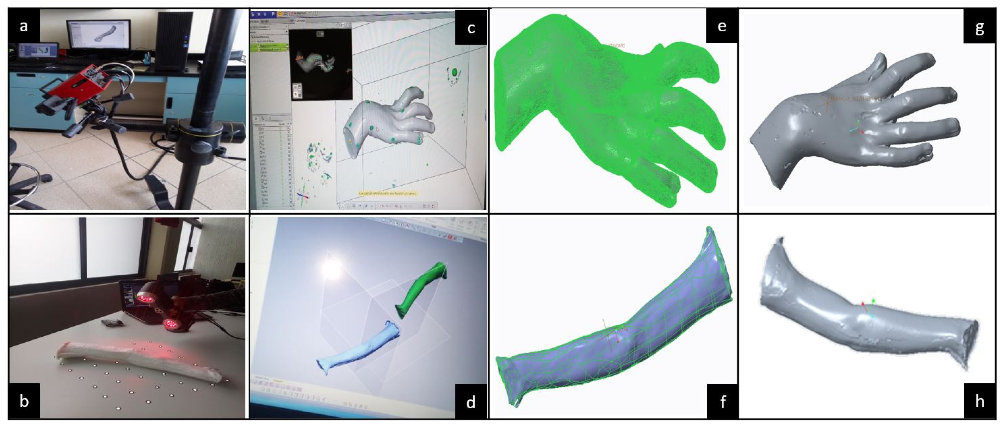
After, 3D digitalization was taken from the silicon products to obtain the skeletal frame of the patient’s upper limb to, virtually, create the MOSAR concept. This virtual model will be useful to manufacture the EPM using stereolithography techniques, for instance.
The ATOS III™ and AMETEK™ scanners are integrated by sensors and two optical lenses. The 3D scanners operate as a camera. Therefore, the lenses must be calibrated prior to starting digitalization. Then, the procedure consists on taking several shots around a piece from any angle until the target area is entirely covered. During the process, lenses need to detect at least three reference points (see white dots in
Figure 8b) which are inside an imaginary 3D cube bounding the 3D workspace of the scanner. The 3D digitalization procedures for hand and forearm dummy models are shown in
Figure 8.
Hand digitalization was done with an ATOS III™ scanner. Due to workspace limitations of this scanner, the forearm was digitalized with an AMETEK™ scanner. For this process, the portability, lightness and not-required calibration of the AMETEK™ scanner allow for an easier handling compared to the ATOS III™. Furthermore, on the AMETEK™ digitalization the dummy forearm was fixed on a platform so the scanner could be triggered at any desired position, while it is inside its work area. Whereas on the ATOS III™, the dummy hand must be laid down on a swivel base because the scanner is fixed in a tripod for motion which limits the workspace. In addition, the ATOS III™ is more sensitive to light, its sensors only detect white mate colors. Hence, the dummy hand must be coated with prior starting the digitalization to reduce noise from the light brightness. Unlike, the AMETEK™ can scan any color, so no coating is needed.
Once the hand and forearm mesh virtual models were achieved, the respective files were exported to Geomagic Design X™ software to delete defects, noise and useless geometries. Continuing with the digital modeling, computer design was done to define the MOSAR virtual concept. The obtained mesh models were manipulated as solid parts in Creo™ software to build an assembly.
The modular architecture of the MOSAR system can be observed in
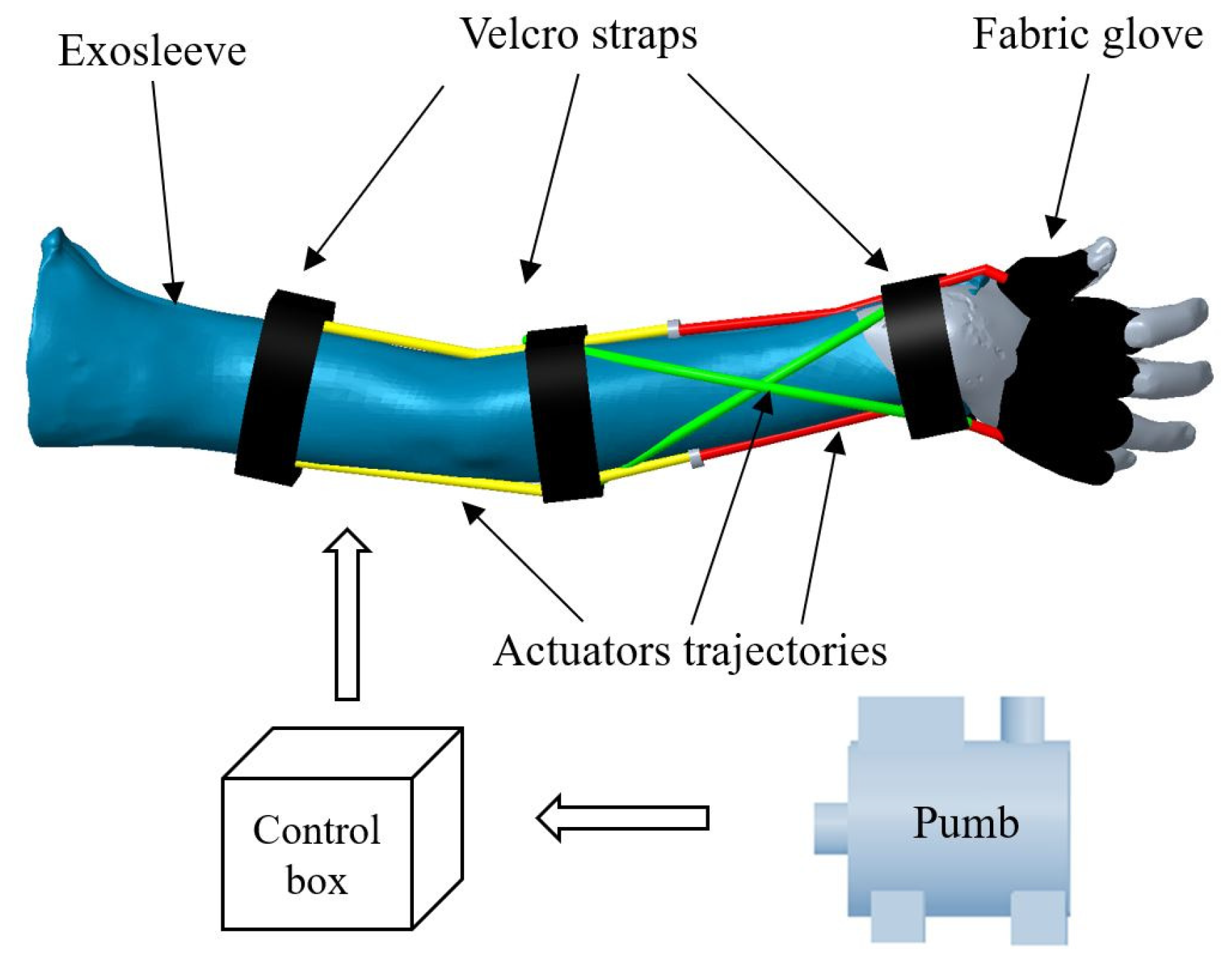
Figure 9 and is integrated by a fixed commercial pump which deliver up to 700 kPa for air supply, a unit box to control the MOSAR system, a fabric exo-sleeve which covers the whole upper limb for elbow-forearm motions and a fabric glove that only supports components for wrist rehabilitation. This architecture is integrated by three modules (red, yellow and green) with two actuators by module. Then, there are six air chambers that content actuators: two in yellow for elbow flexion-extension, two twisted in green for forearm pronation-supination and radial and ulnar deviations and two in red for wrist flexion-extension. All components are fasten to the skin with Velcro straps at each joint.
The definition of the MOSAR constraints goes hand in hand with the condition of the patient. Thus, the MOSAR system will only exert the right upper limb rehabilitation for a hemiplegic child. Particularly, this SWD will tackle hyperspasticity at the elbow, forearm and wrist. The operating conditions of the device are determined by the passive ROM of the child that was previously measured in order to guarantee his physical well-being. The MOSAR device will work only on the sagittal plane of the right side and can only execute one movement at a time on each joint. This soft mobilizer will be useful for the anthropometric ranges of children between nine to eleven years old.
Furthermore, MOSAR’s characterization is derived also from the design criteria that were defined in
Section 2. The MOSAR is based on a patient-centered approach providing passive motion guidance on elbow, forearm and wrist using a bilateral mode of intervention. This system seeks to promote the active use of the impaired limb to overcome motor dysfunctions by means of a complete rehabilitation program that uses the healthy limb to stimulate the impaired one.
The MOSAR exo-sleeve has four DOF: one for elbow (flexion-extension), one for forearm (pronation-supination), two for wrist (flexion-extension and radial-ulnar deviation) using a modular architecture which allows to rehabilitate a desired joint. Additionally, the device is endowed with a mobile inlet for pneumatic power supply that drives six antagonist actuators. This feed can be connected depending on the target muscles to save the number of components compared with other designs. The whole assembly is mounted on a closed configuration to restrict direct contact with the patient’s skin.
Table 4 summarizes the MOSAR’s features.
Continuing with phase 2, MOSAR’s characterization should also include the definition of a mathematical model and control strategy. However, these aspects are not included in the scope of this paper and will be reported separately.
4. Discussion
The design methodology reported in this paper focuses on the creation of SWD based on a patient-centered design as an alternative solution that minimizes trial and error tasks. The proposed design methodology seeks to empathize with patients’ needs and provide them a custom SWD depending on their physical condition.
This methodology is also oriented to ensuring patients’ safety since the SWD is integrated by a control unit to drive its safe and precise operation. In addition, the usability conditions encompass medical advice while mobility criteria enhance system performance through the definition of the operational conditions.
This methodology has several advantages due to its new proposed structure that encompasses research, development and innovation of SWD. Additionally, the number of steps could be reduced depending on the case study, on the control strategy (open or closed-loop) and on the feasibility of the SWD conception.
The current methodology is based on an integral assessment from a neurologist, a therapist and EMG tests to provide an accurate diagnosis about patient’s condition. Moreover, specialists’ feedback allows to define the appropriate SWD task depending on each necessity. This valuable information is important since the specialists are the ones that will be supervising the SWD’s operation everyday.
It is noted that the SWD methodology is a reference frame for researchers, engineers, therapists and patients since it provides conception, manufacturing, experimentation and use guidelines for safe and functional SWD systems. This detailed methodology allows to identify, in a relatively easy way, patient’s need, device’s task, attributes and constraints of the system for its development.
The methodology is not limited to a specific case study, it can be applied in different scenarios to anyone who requires aid SWD support regardless of pathology, age, sex or the number of impaired limbs of the patient. This is guaranteed thanks to the fact that this methodology is a customized BTM so, it can be adapted to the needs of each patient. The parametrized SWD could be scaled to other people with similar medical diagnosis. Nevertheless, ROM and anthropometric measurements must be assessed for each case study.
Unlike other approaches where design, fabrication and assessment are performed separately, these aspects are linked through two stages and four phases for research, development and innovation of SWD systems. This guarantees a reduction on time and reworks. Moreover, multidisciplinary groups are required to develop, successfully, the methodology.
This methodology offers the guidelines to market the SWD as available products, including an innovation vision. Most of the reported developments consider a laboratory prototype as the final product of the research. Instead of those works, this methodology determines the level of maturity of the final product using TRL guidelines.
The proposed methodology can be followed to develop different SWD through the use of a modular platform that can be adapted to different scenarios depending on patient’s needs. Since the suggested design criteria could be applied not only to medical devices, they are valid for other applications such as gripping, loading up heavy parts or exploration in hazardous environments, for instance.
The use of reverse engineering to generate the conceptual design of the SWD saves time. So, manufacturing phase can start earlier than in conventional approaches. Reverse engineering seeks to accelerate the transition between development and innovation for broad applications.
In addition, some opportunity areas have been detected to improve this work. For example, the entire process’s time, particularly for actuators fabrication, could be reduced. There is still room for adopting new energy sources, particularly in pneumatic actuation that requires robust and lightweight power supplies that do not tie the patient to a fixed station.
Following this methodology, soft wearable devices can be created in a relatively easy way. Then, any person working on soft robotics, such as engineers or researchers, are asked to implement this methodology or to use the tools that it provides.
5. Conclusions and Future Work
The aforementioned methodology will serve for future SWD developments and can be applied to different areas such as military, mobile robots, transportation and medical applications, for instance. The reported technological platform could be adapted to other soft robotics applications (hands, knee or ankle, for example). Since the considerations involved in the methodology and the platform are invariant, these two products can be applied in different medical areas.
The design methodology seeks to unify medical, therapeutic and engineering guidelines for the research, development and innovation of SWD systems. This methodology establishes criteria and guidelines as a reference frame for further SWD developments.
The steps related to this methodology have been described in detail. Additionally, this paper classifies 27 design criteria of soft wearable devices into three main categories: mobility (13 criteria), usability (11 criteria) and control (three criteria) with the purpose of guaranteeing functionality and safe interactions between the patient, the SWD and the environment.
The aim of this methodology is not only to develop an experimental physical model but also to seek for a future commercialization stage of the device as an available product. This systematized methodology seeks to make use of BTM principles, available infrastructure, design tools and technology to validate the functionality of a SWD allowing the acceleration of the technology readiness level for the creation of more new generation products by reducing the time between the conceptual design and the product release.
To the best of the author’s knowledge, this paper also provides a first technological platform with a family of eight exo-products for the main joints of upper and lower limbs. The combination of design criteria can produce more than 50 products for SWD with modular architectures that facilitate product diversification and marketing depending on the clinical assessment of the patient.
The MOSAR system is a SWD which has been designed using the proposed methodology under a patient-centered approach. This work seeks to satisfy the recommendations that two specialists (a neurologist and a therapist) provided based on three medical assessments. In order to guarantee the patient’s safety and to follow a rehabilitation protocol that was determined for a specific patient, a virtual model of the MOSAR system was created.
The implementation of the reported methodology for the development of the MOSAR system is currently in phase 2 (step 17). Methodology criteria facilitated the MOSAR’s attributes and constraints definitions for upper limb rehabilitation in children with hemiplegia. Future work, concerns the synthesis of a control law and the development of the manufacturing and experimental phases for the MOSAR system. This implementation will be reported in future communications.

 ,
, 


