Development of a Novel Variable-Diameter Wheel


Abstract
Featured Application
Abstract
1. Introduction
2. Wheel Configuration and Transmission System
2.1. Wheel Configuration
2.2. Transmission System
- (1)
- M1 → left sun gear (a1) → middle planet gear (c2) → middle ring gear (b2).
- (2)
- Electric motor (M2) → right planet carrier (H2) and left planet carrier (H1) → left (c1), middle (c2), and right planet gears (c3) → left (b1), middle (b2), and right ring gears (b3).
3. Design Methodology
3.1. Kinematic Analysis
3.2. Optimization Design
3.2.1. Design Variables
3.2.2. Objective Function
3.2.3. Constraint Function
3.2.4. Optimization Results
4. Load–Deflection Relationship
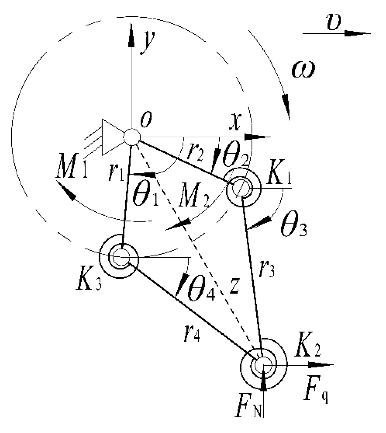
4.1. Pseudo-Rigid-Body Model
4.2. Virtual Work of Forces
4.3. Virtual Work of Moments
4.4. Virtual Work of Springs
4.5. Load–Deflection Behavior
5. Modified PRBM and Validation
5.1. Modified PRBM
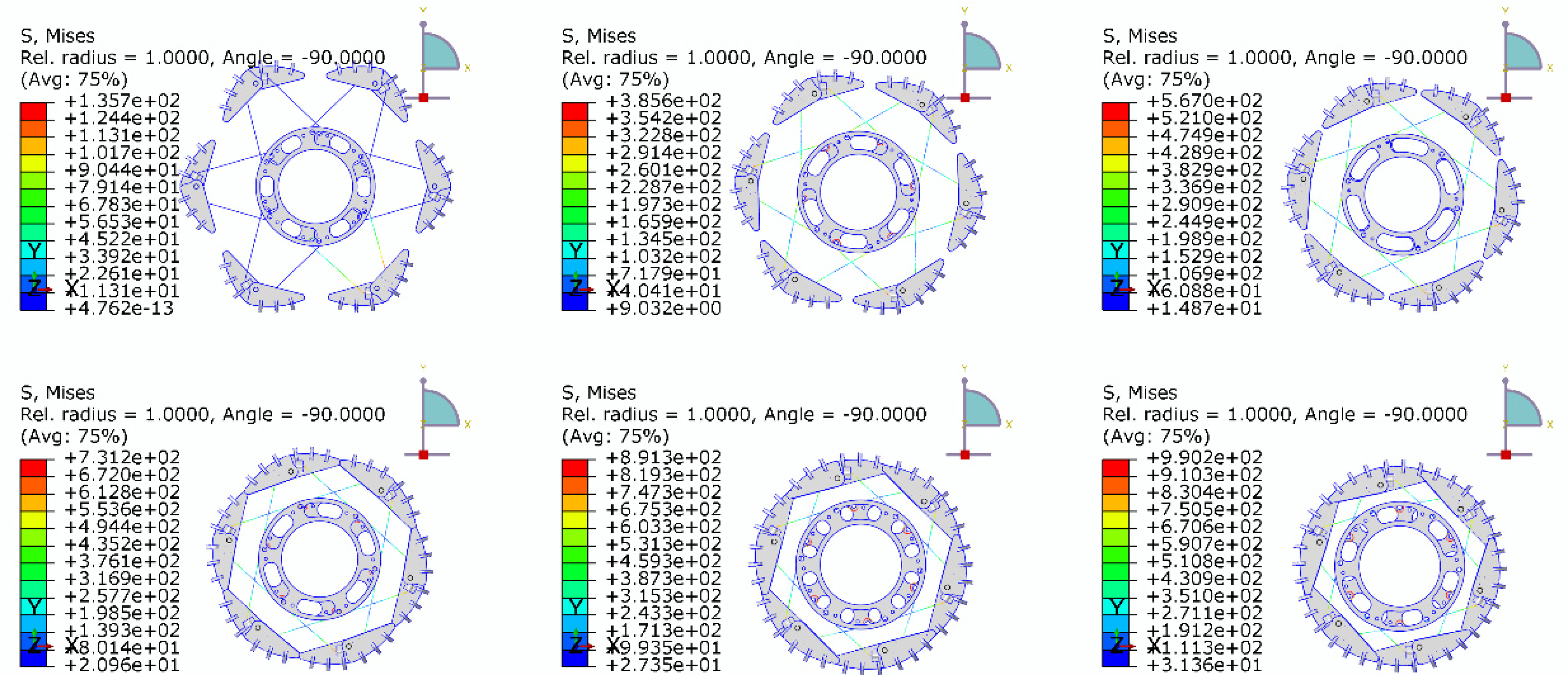
5.2. Validation
6. Conclusions
Author Contributions
Funding
Conflicts of Interest
References
- Alamdari, A.; Krovi, V.N. Design of articulated leg–wheel subsystem by kinetostatic optimization. Mech. Mach. Theory 2016, 100, 222–234. [Google Scholar] [CrossRef]
- Ghotbi, B.; González, F.; Kövecses, J.; Angeles, J. Mobility evaluation of wheeled robots on soft terrain: Effect of internal force distribution. Mech. Mach. Theory 2016, 100, 259–282. [Google Scholar] [CrossRef]
- Xie, X.; Gao, F.; Huang, C.; Zeng, W. Design and development of a new transformable wheel used in amphibious all-terrain vehicles (A-ATV). J. Terramech. 2017, 69, 45–61. [Google Scholar] [CrossRef]
- Asnani, V.; Delap, D.; Creager, C. The development of wheels for the lunar roving vehicle. J. Terramech. 2009, 46, 89–103. [Google Scholar] [CrossRef]
- Zakrajsek, J.; McKissock, D.; Woytach, J.; Zakrajsek, J.; Oswald, F.; McEntire, K.; Goodnight, T. Exploration Rover Concepts and Development Challenges. In Proceedings of the 1st Space Exploration Conference: Continuing the Voyage of Discovery, Orlando, FL, USA, 30 January–1 February 2005; pp. 1–23. [Google Scholar]
- Bekker, M.G. Introduction to Terrain-Vehicle Systems, 1st ed.; University of Michigan Press: Ann Arbor, MI, USA, 1969; pp. 1–20. ISBN 0472041444. [Google Scholar]
- Bekker, M.G. Off-The-Road Locomotion: Research and Development in Terramechanics, 1st ed.; University of Michigan Press: Ann Arbor, MI, USA, 1960; pp. 1–30. ISBN 0472041428. [Google Scholar]
- Siddiqi, A.; Weck, O.L. Reconfigurability in planetary surface vehicles. Acta Astronaut. 2009, 64, 589–601. [Google Scholar] [CrossRef]
- Zeng, W.; Gao, F.; Jiang, H.; Huang, C.; Liu, J.; Li, H. Design and analysis of a compliant variable-diameter mechanism used in variable-diameter wheels for lunar rover. Mech. Mach. Theory 2018, 125, 240–258. [Google Scholar] [CrossRef]
- Abad-Manterola, P.; Burdick, J.W.; Nesnas, I.A.; Chinchali, S.; Fuller, C.; Zhou, X. Axel Rover Paddle Wheel Design, Efficiency, and Sinkage on Deformable Terrain. In Proceedings of the IEEE International Conference on Robotics and Automation(ICRA), Anchorage, AK, USA, 3–7 May 2010; pp. 2821–2827. [Google Scholar]
- Ming, H.; Bao-Long, S.; Wen-Hua, C.; Dan-Min, H.; De-Bei, L.; Ya-Di, H. Structure Synthesis & Configuration Transformation of Variable Topology Repeated Foldable Wheel. In Proceedings of the IEEE International Conference on Robotics and Biomimetics (ROBIO), ShenZhen, China, 12–14 December 2013; pp. 85–90. [Google Scholar]
- Bidaud, P.; Benamar, F.; Poirier, S. An Expandable Mechanism for Deployment and Contact Surface Adaptation of Rover Wheels. In Climbing and Walking Robots; Springer: Berlin/Heidelberg, Germany, 2006; pp. 1053–1060. [Google Scholar]
- Grand, C.; Bidaud, P.; Jarrassé, N. Innovative Concept of Unfoldable Wheel with an Active Contact Adaptation Mechanism. In Proceedings of the 12th IFToMM World Congress, Besancon, France, 17–21 June 2007. [Google Scholar]
- Hirose, S.; Kuwabara, H. Design of three-wheeled planetary rover Tri-star II. J. Robot. Mechatron. 2000, 12, 446–452. [Google Scholar] [CrossRef]
- Aoki, T.; Murayama, Y.; Hirose, S. Development of a transformable three-wheeled lunar rover: Tri-star IV. J. Field Robot. 2014, 31, 206–223. [Google Scholar] [CrossRef]
- Sun, G.; Gao, F.; Sun, P. Design and mobility performance study of spring wheel for lunar rover. China Mech. Eng. 2009, 20, 134–137. [Google Scholar]
- Midha, A.; Norton, T.W.; Howell, L.L. On the nomenclature, classification, and abstractions of compliant mechanisms. ASME J. Mech. Des. 1994, 116, 270–279. [Google Scholar] [CrossRef]
- Howell, L.L.; Magleby, S.P.; Olsen, B.M. Handbook of Compliant Mechanisms, 1st ed.; Wiley: New York, NY, USA, 2013; pp. 1–2. ISBN 1119953456. [Google Scholar]
- Sun, P.; Gao, F.; Li, W.; Sun, G. Analysis of traction trafficability of diameter-variable wheel for planetary rover. J. Beijing Univ. Aeronaut. Astronaut. 2007, 33, 1404–1407. [Google Scholar]
- Cui, Y.; Gao, F. Kinematic modeling and analysis of variable diameter wheeled lunar rover. J. Beijing. Univ. Aeronaut. Astronaut. 2008, 34, 348–352. [Google Scholar]
- Machekposhti, D.F.; Tolou, N.; Herder, J.L. A review on compliant joints and rigid-body constant velocity universal joints toward the design of compliant homokinetic couplings. ASME J. Mech. Des. 2015, 137, 032301. [Google Scholar] [CrossRef]
- Valentini, P.P.; Pennestrì, E. Second-order approximation pseudo-rigid model of leaf flexure hinge. Mech. Mach. Theory 2017, 116, 352–359. [Google Scholar] [CrossRef]
- Hongzhe, Z.; Dong, H.; Shusheng, B. Modeling and analysis of a precise multibeam flexural pivot. ASME J. Mech. Des. 2017, 139, 081402. [Google Scholar] [CrossRef]
- Norton, R.L. Design of Machinery: An Introduction to the Synthesis and Analysis of Mechanisms and Machines; McGraw-Hill Higher Education: Boston, MA, USA, 2004; pp. 188–232. ISBN 0-07-247076-1. [Google Scholar]
- Sanò, P.; Verotti, M.; Bosetti, P.; Belfiore, N.P. Kinematic synthesis of a D-Drive MEMS Device with rigid-body replacement method. ASME J. Mech. Des. 2018, 140, 075001. [Google Scholar] [CrossRef]
- Howell, L.L. Compliant Mechanisms; John Wiley & Sons: New York, NY, USA, 2001; pp. 162–168. ISBN 0-471-38478-X. [Google Scholar]
- Venkiteswaran, V.K.; Su, H.J. Pseudo-rigid-body models for circular beams under combined tip loads. Mech. Mach. Theory 2016, 106, 80–93. [Google Scholar] [CrossRef]
- Venkiteswaran, V.K.; Su, H.J. A versatile 3R pseudo-rigid-body model for initially curved and straight compliant beams of uniform cross section. ASME J. Mech. Des. 2018, 140, 092305. [Google Scholar] [CrossRef]
- Tanık, E.; Parlaktaş, V. Compliant cardan universal joint. ASME J. Mech. Des. 2012, 134, 021011–021015. [Google Scholar] [CrossRef]
- Tanık, E.; Söylemez, E. Analysis and design of a compliant variable stroke mechanism. Mech. Mach. Theory 2010, 45, 1385–1394. [Google Scholar] [CrossRef]
- Tanık, E. Analysis and design of an underactuated compliant five-bar mechanism. Mech. Mach. Theory 2016, 102, 123–134. [Google Scholar] [CrossRef]
- Beitz, W.; Kuttner, K.H. Dubbel-Handbook of Mechanical Engineering; Springer: London, UK, 1994; pp. 50–63. ISBN 3-540-19868-7. [Google Scholar]
- Xiao, W.; Zhang, Y. Design of manned lunar rover wheels and improvement in soil mechanics formulas for elastic wheels in consideration of deformation. J. Terramech. 2016, 65, 61–71. [Google Scholar] [CrossRef]
- Jouaneh, M.; Yang, R. Modeling of flexure-hinge type lever mechanisms. Precis. Eng. 2003, 27, 407–418. [Google Scholar] [CrossRef]


| Design Parameters | Magnitude |
|---|---|
| α1 | 149° |
| α2 | 67° |
| β1 | 84° |
| β2 | 45° |
| Dcq | 194 mm |
| l | 140 mm |
| Parameters | Values |
|---|---|
| θ10 | 93.5° |
| Dcq | 182 mm |
| θ20 | 26.5° |
| r1 | 97 mm |
| r2 | 97 mm |
| r3 | 140 mm |
| r4 | 140 mm |
| d | 4 mm |
| n1 | 10 |
| n2 | 6 |
| D | 14 mm |
| l | 140mm |
| θ1 | θ2 | M1 (N·mm) | M2 (N·mm) | ||||
|---|---|---|---|---|---|---|---|
| PRBM | FEA | %Diff | PRBM | FEA | %Diff | ||
| 103.5° | 22.5° | −31,572.65 | −31,880.05 | 0.96% | 19,340.47 | 19,575.3 | 1.2% |
| 113.5° | 18.5° | −54,471.28 | −54,622.25 | 0.28% | 43,365.75 | 43,428.14 | 0.14% |
| 123.5° | 14.5° | −73,162.13 | −73,031.2 | 0.18% | 63,226.63 | 62,952.67 | 0.44% |
| 133.5° | 10.5° | −86,752.77 | −86,267.8 | 0.56% | 77,993 | 77,375.2 | 0.80% |
| 143.5° | 6.5° | −94,515.47 | −93,952.3 | 0.60% | 86,900.66 | 86,182.82 | 0.83% |
| 151.5° | 2.5° | −96,336.40 | −96,104.2 | 0.24% | 89,592.73 | 89,190.67 | 0.45% |
© 2019 by the authors. Licensee MDPI, Basel, Switzerland. This article is an open access article distributed under the terms and conditions of the Creative Commons Attribution (CC BY) license (http://creativecommons.org/licenses/by/4.0/).
Share and Cite
Zeng, W.; Xu, G.; Jiang, H.; Gao, F. Development of a Novel Variable-Diameter Wheel. Appl. Sci. 2019, 9, 4631. https://doi.org/10.3390/app9214631
Zeng W, Xu G, Jiang H, Gao F. Development of a Novel Variable-Diameter Wheel. Applied Sciences. 2019; 9(21):4631. https://doi.org/10.3390/app9214631
Chicago/Turabian StyleZeng, Wen, Guoyan Xu, Hui Jiang, and Feng Gao. 2019. "Development of a Novel Variable-Diameter Wheel" Applied Sciences 9, no. 21: 4631. https://doi.org/10.3390/app9214631
APA StyleZeng, W., Xu, G., Jiang, H., & Gao, F. (2019). Development of a Novel Variable-Diameter Wheel. Applied Sciences, 9(21), 4631. https://doi.org/10.3390/app9214631